Husqvarna WS440HF Workshop Manual
Hide thumbs
Also See for WS440HF:
- Price list (48 pages) ,
- Workshop manual (165 pages) ,
- Workshop manual (165 pages)

Related Manuals for Husqvarna WS440HF


Summary of Contents for Husqvarna WS440HF
- Page 1 Workshop manual WS440HF, WS482HF, PP440HF, PP480HF, PP490HF HUSQVARNA CONSTRUCTION PRODUCTS...
- Page 2 LEGEND...
-
Page 3: Table Of Contents
TABLE OF CONTENTS 3. Literature Workshop Manual ���������������������������������������������������������������������������������������������������������������������������������������� 7 Spare Parts Catalogue ����������������������������������������������������������������������������������������������������������������������������������� 7 Operator’s Manual ���������������������������������������������������������������������������������������������������������������������������������������� 7 4. Safety Instructions General ����������������������������������������������������������������������������������������������������������������������������������������������������������� 8 Warning and Information ��������������������������������������������������������������������������������������������������������������������������� 8 ESD General Notice ������������������������������������������������������������������������������������������������������������������������������������� 8 Emergency Stop Button ������������������������������������������������������������������������������������������������������������������������������� 9 Start Blade Rotation ������������������������������������������������������������������������������������������������������������������������������������� 9 Transport and Storage ����������������������������������������������������������������������������������������������������������������������������������... - Page 4 TABLE OF CONTENTS 9. Remote Control RC Service Menu ����������������������������������������������������������������������������������������������������������������������������������������71 10. Repair Instructions Wall Saw 10.1. Blade Gard Replacing the Bearings in the Blade Guard Guide Wheels ������������������������������������������������������������������72 Disassembly ���������������������������������������������������������������������������������������������������������������������������������������������72 Assembly ��������������������������������������������������������������������������������������������������������������������������������������������������72 Calibrating the Two Adjustable Wheels ���������������������������������������������������������������������������������������������������73 Checking that the Blade Guard Guide is parallel with the Blade ��������������������������������������������������������73 Remove Blade Flange ���������������������������������������������������������������������������������������������������������������������������������74 Renovate Blade Flange �������������������������������������������������������������������������������������������������������������������������������74 10.2.
- Page 5 TABLE OF CONTENTS 10.3. Saw Head Remove Covers �������������������������������������������������������������������������������������������������������������������������������������������� 98 Remove Handle/Blade Guard Mount ����������������������������������������������������������������������������������������������������� 98 Dismantling the Saw Head Electronics ���������������������������������������������������������������������������������������������������99 Click for 3D steps ���������������������������������������������������������������������������������������������������������������������������������������99 Remove Feed Motors �������������������������������������������������������������������������������������������������������������������������������101 Remove Feed Motor Gearbox �����������������������������������������������������������������������������������������������������������������102 Adjust play on Feed Motor Gearbox �����������������������������������������������������������������������������������������������������103 Reassemble the Feed Motor Gearbox ����������������������������������������������������������������������������������������������������104 Remove Motor ������������������������������������������������������������������������������������������������������������������������������������������105 Dismantle the Motor �������������������������������������������������������������������������������������������������������������������������������106...
- Page 6 TABLE OF CONTENTS 11. Repair Instructions Power Pack Opening the PP 490 ���������������������������������������������������������������������������������������������������������������������������������124 Replacing the Cover Seals ������������������������������������������������������������������������������������������������������������������������125 Replacing the CAN Bus Contact �����������������������������������������������������������������������������������������������������������126 Replacing the Voltage Inducator Lamp �������������������������������������������������������������������������������������������������127 Replacing the Power Inlet and the Residual current device (RCD) ���������������������������������������������������128 Replacing the Single Phase Socket ����������������������������������������������������������������������������������������������������������130 Replacing the Emergency Stop Button ��������������������������������������������������������������������������������������������������131 Replacing the Harting Connector Assembly, Wall Saw �����������������������������������������������������������������������132...
-
Page 7: Literature
HUSQVARNA CONSTRUCTION PRODUCTS reference to the beginning of each chapter� Spare Parts Catalogue This catalogue documents all of the spares for the Husqvarna PP 490 IPL, WS 220 HF, 2012-12, 583 94 35-01 Unit� PP 490 HF The catalogue contains complete... -
Page 8: Safety Instructions
SAFETY INSTRUCTIONS 4. SAFETY INSTRUCTIONS General • No one may repair the WS400HF and related power pack (PP440, PP480 or PP490), hereafter called PP400HF,unless they have read and understood the content of this workshop manual� • This Workshop Manual is written for personnel with general knowledge about the repair and service of WS400HF and PP400HF�... -
Page 9: Emergency Stop Button
SAFETY INSTRUCTIONS Emergency Stop Button The powerpack is equipped with an emergency stop and the remote control with a stop botton� These are used to be able to quickly shut down the power pack� Note that voltage will still be present inside the PP400HF unit after activating this button�... -
Page 10: Tools And Special Tools
TOOLS AND SPECIAL TOOLS 5. TOOLS AND SPECIAL TOOLS In the list below you will find the tools and the special tools used in this workshop manual. Tools Tool Tool no. Description Airfluch 525 45 52-01 Allen Key, Kit 2�5 - 10 mm Bearing puller 523 05 79-01 Center Punch... - Page 11 TOOLS AND SPECIAL TOOLS Tool Tool no. Description 531 28 02-47 Grease Petro-Canada Peerless OG2 Red Harting special tool 522 93 44-01 (6-pin) 522 93 43-01 (3-pin) Heater Gun Heat silicone 150 °C + Heat Transfer Paste Indicator Clock Knife/Razor blade Loctite Long Socket Multiprogrammer...
- Page 12 TOOLS AND SPECIAL TOOLS Tool Tool no. Description Rubber Mallet Scissor Screwdriver Service tool 523 05 84-01 531 11 95-41 (18 mm) Socket 531 11 95-34 (19 mm) Soldering Iron Slide Hammer 584 39 99-01 575 46 64-01 Special puller, pivoting arm Special socket, blade clutch 523 05 76-01 Special socket, center gear shaft...
- Page 13 TOOLS AND SPECIAL TOOLS Tool Tool no. Description Steel Ruler, 0 - 300 mm Torx Universal Bearing Puller 504 90 90-02 Universal Pliers Vice Workshop Press Wrench 531 11 95-33...
- Page 14 COMPONENTS - NAVIGATION 6. COMPONENTS - NAVIGATION WS 482 HF 1� Blade guard 8� Cooling water out to blade a� Outer section 9� Cooling water in from PP b� Centre section 10� Wall saw carriage lever & lock 2� Cooling water connector for blade 11�...
-
Page 15: Components - Navigation
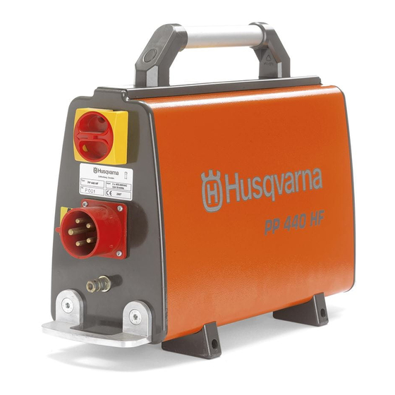
COMPONENTS - NAVIGATION PP 490 (External) 1� Woltage indicator lamp 11� Handle 2� Emergency stop button 12� Ground-fault circuit breaker (Residual Current Device -RCD) 3� CAN connector for remote control 13� Power inlet connector 4� Reset button 230V- Only 5-pin machines 14�... -
Page 16: Pp 490 (Internal)
COMPONENTS - NAVIGATION PP 490 (Internal) 1� EMC filter board 12� Main board (Seen from the other side) 2� Varistor VDR 510V 13� Water valve 3� Cooling plate 14� CAN-bus connector 4� Fuse 1A 15� Controller board 5� Main contactor 16�... -
Page 17: Service And Maintenance
SERVICE AND MAINTENANCE SERVICE AND MAINTENANCE 7. SERVICE AND MAINTENANCE The service-related differences between the WS 480: WS480 and WS440 1� 2 micanical gears� (In the arm) 2� Gear selector WS 480 3� Larger motor with an extra water connection� 4�... -
Page 18: The Service-Related Differences Between The Pp480 And Pp440
SERVICE AND MAINTENANCE SERVICE AND MAINTENANCE The service-related differences between the PP480 and PP440 WS 480: PP 480 1� Seperate EMC filter board (Intergrated in the inverter inside PP440) 2� Longer chassis 3� Diffrent Inverter board 4� Diffrent Controller board PP 440... -
Page 19: The Service-Related Differences Between The Pp480 And Pp490
SERVICE AND MAINTENANCE SERVICE AND MAINTENANCE The service-related differences between the PP480 and PP490 WS 490: PP 490 1� Diffrent EMC filter board 2� Varistor VDR 510V 3� Fuse 1A 4� WS contactor 5� PRIME contactor (DM-PC) 6� Fuse 15A 7�... -
Page 20: Funktion Test Ws400
SERVICE AND MAINTENANCE SERVICE AND MAINTENANCE Funktion Test WS400 HF Cleaning These function tests help to reveal the current condition of the feeding Clean the WS 482, PP 480, cables and motor, slip clutches, and gears. The results of these tests will help you to determine what course of action to take. -
Page 21: Function Test Power Pack
SERVICE AND MAINTENANCE SERVICE AND MAINTENANCE Check the Pivoting Arm Play 1� Make a status check by attaching an indicator clock� 2� Gently move arm back and forth with two fingers, do not press hard� 3� Measure the play� It should be less than ±... -
Page 22: Function Test Remote Control
SERVICE AND MAINTENANCE SERVICE AND MAINTENANCE Function test Remote Control Checking Potentiometers 1� Connect the RC Unit to the PP480 with the CAN-bus cable� 2� At the main screen, push OK to get into the Menu� 3� Use the up or down arrows to go to Service menu�... - Page 23 SERVICE AND MAINTENANCE SERVICE AND MAINTENANCE Adjusting the guide wheels In order for the saw to run stably and make a straight cut, the four guide wheels must rest against the rail and not have too much play� Check the guide wheels during service�...
- Page 24 SERVICE AND MAINTENANCE SERVICE AND MAINTENANCE Adjust the saw carriage As the saw wears, after a number of hours working, it can be a good idea to ensure that the saw sits firmly in the saw carriage and rail� If not, the handle probably needs adjusting: 1�...
-
Page 25: Ws400 Hf Service
SERVICE AND MAINTENANCE SERVICE AND MAINTENANCE WS400 HF Service When it 100h 200h Page comes in to the workshop Overal check for damaged/loose parts and adjust or replace as nessesary� That the Handle/Blade Guard Mount is correctly secured and not loose in any way Play and wear on the travel feed wheel and it’s Adjusting the guide bearing... - Page 26 SERVICE AND MAINTENANCE SERVICE AND MAINTENANCE When it 100h 200h Page comes in to the workshop Replace the o-rings and seals on the feed Service 200h (p� 29) motors Replace all the seals for the saw head Service 200h (p� 29) electronics, don’t miss the blue silicon seals Replace the pins, connectors and ground Dismantling the Saw...
-
Page 27: Power Pack Service
SERVICE AND MAINTENANCE SERVICE AND MAINTENANCE SERVICE AND MAINTENANCE SERVICE AND MAINTENANCE Power Pack Service When it 100h 200h Page comes in to the workshop Overall check for damaged/loose parts and adjust or replace as nessesary� Check continuity of the earth wiring through out the machine�... -
Page 28: Service 100H
SERVICE AND MAINTENANCE SERVICE AND MAINTENANCE Service 100h 1. Blade Flange Bolt Replace the blade bolt on the blade flenge. 2. Blade Guard Replace the guide blocks on the blade guard� 3. Blade Guard Guide Replace the bearings on the blade guard guide wheels�... -
Page 29: Service 200H
SERVICE AND MAINTENANCE SERVICE AND MAINTENANCE Service 200h 1. Blade Flange Bolt Replace the blade bolt on the blade flenge. 2. Blade Guard Replace the guide blocks on the blade guard� 3. Blade Guard Guide Replace the bearings on the blade guard guide wheels�... - Page 30 SERVICE AND MAINTENANCE SERVICE AND MAINTENANCE 9. Feed Shaft Replace all the o-rings on the feed shaft� Assemble the Track Feed Slip Clutch (p� 115) 10. Feed Motor Replace the o-rings and seals on the feed motors� Remove Feed Motors (p� 101) 11.
-
Page 31: Technical Information And Troubleshooting
TECHNICAL INFORMATION AND TROUBLESHOOTING 8.TECHNICAL INFORMATION AND TROUBLESHOOTING General All troubleshooting in this manual is based on the fact that you can reproduce the perceived problem� A good multimeter is needed� Preferably the one recommended in the tools section� • Make sure to set the multimeter to AC power when measuring grid power� •... -
Page 32: Fault Codes Prime Tools
TECHNICAL INFORMATION AND TROUBLESHOOTING Fault Codes PRIME tools Several of the error messages below may appear simultaneously� It is important to check all the messages in order to make a correct analysis of the error. When the first error message is dismissed the next one will appear. * XX different numbers depending on the tool that is connected to the power unit Message Reason... - Page 33 TECHNICAL INFORMATION AND TROUBLESHOOTING Code Message Reason Action This error may be caused by a faulty Check all cabels and cable cable or connection between the Main connections� If it doesn’t help F0118 No DSP communication Board and control board� Otherwise, the then replace first control bard and Main Board and/or control board card then Main Board one at the time�...
-
Page 34: Error Message (Led Indicator) Prime Tools
TECHNICAL INFORMATION AND TROUBLESHOOTING Error Message (LED indicator) PRIME tools In case of any error, the error code will flash on the PRIME™ tool according to the table� Measures for acknowledging fault messages: • Activate the trigger on the connected tool� No further action is required if the flashing stops� If the fault persists, follow the instructions given in the troubleshooting guide or get in touch with an authorized dealer�... -
Page 35: Fault Codes
TECHNICAL INFORMATION AND TROUBLESHOOTING Fault Codes Fault code Page F01 Motor overheated F02 Power Overheated F03 Low Voltage F04 High Voltage F05 Over Current F06 No Hall Sensor Track F07 No Hall Sensor Arm F08 Track Feed Overload F09 Arm Feed Overload F10 Blade Jam F11 General HF Fault / Ground fault or no saw head F12 Non-compatible Saw Unit... - Page 36 TECHNICAL INFORMATION AND TROUBLESHOOTING Fault code Page No Tool Communications Internal Water Valve Fuses in the wall keep tripping External Ground Fault Circuit Breaker trips when turning on or off the equipment PP Blade Motor Circuit PP Feed Motor Circuit WS-contactor and DM/PC-contactor...
-
Page 37: Trouble Shooting Tree
TECHNICAL INFORMATION AND TROUBLESHOOTING Trouble Shooting Tree Water Connection p.52 Replace the Motor Replace the Motor Temp Sensor p.109 Temp Sensor p.109... - Page 38 TECHNICAL INFORMATION AND TROUBLESHOOTING Water Connection p.52 Dismantle the Inverter Board p.142 Power Supply p.46 Dismantle the Inverter Board p.142...
- Page 39 TECHNICAL INFORMATION AND TROUBLESHOOTING Harting connector and orange main cable checkup p.55 Blade Motor Mecanics p.54 PP Blade Motor Circuit p.64 Disassemble Arm p.79 Blade Motor Mecanics p.54 Blade Motor Mecanics p.54 Blade Motor Electrics p.54...
- Page 40 TECHNICAL INFORMATION AND TROUBLESHOOTING Harting connector and orange main cable checkup p.55 Simplified Wiring Diagram p.159 Simplified Wiring Diagram p.159 Function test Remote Control p.22...
- Page 41 TECHNICAL INFORMATION AND TROUBLESHOOTING Feed Motors p.52 PP Feed Motor Circuit p.65 WS Setup p.60 Harting connector and orange main cable checkup p.55 Inspect Clutch Inspect the Clutch p.78 Gear Shafts p.82 F05 p.39...
- Page 42 TECHNICAL INFORMATION AND TROUBLESHOOTING Generator and Transformer Setup p.58 WS-contactor and DM/PC-contactor p.65 Harting connector and orange main cable checkup p.55 F05 p.39 Assemble the saw Head Electronics p.121 Ground or Neutral Fault Inlet Side p.51 Ground Fault Outlet Side p.52...
- Page 43 TECHNICAL INFORMATION AND TROUBLESHOOTING Function test Remote Control p.22...
- Page 44 TECHNICAL INFORMATION AND TROUBLESHOOTING Power Supply p.46...
- Page 45 TECHNICAL INFORMATION AND TROUBLESHOOTING PP 490 (Internal) p. 16 Replacing the Main Board p.138 Dismantle the Inverter Board p.142...
- Page 46 TECHNICAL INFORMATION AND TROUBLESHOOTING Contactor and Emergency Stop p.49 Harting connector and orange main cable checkup p.55 Power Inlet Connector in PP p.47 Power Inlet Connector in PP p.47...
- Page 47 TECHNICAL INFORMATION AND TROUBLESHOOTING Replacing the Power Inlet and the Residual current device (RCD) p.127 Contactor and Emergency stop p.49 RCD p.48...
- Page 48 TECHNICAL INFORMATION AND TROUBLESHOOTING Power Inlet Connector in PP p.47 Contactor and Emergency stop p.49 Ground or Neutral Fault Inlet Side p.51 Replacing the Power inlet and the Residual current device (RCD) p.127 Contactor and Emergency stop p.49...
- Page 49 TECHNICAL INFORMATION AND TROUBLESHOOTING Power Supply p.46, Power inlet connector in PP p.47 RCD p.48...
- Page 50 TECHNICAL INFORMATION AND TROUBLESHOOTING Power Supply p.46, Power inlet connector in PP p.47, RCD p.48 Contactor and Emergency stop p.49...
- Page 51 TECHNICAL INFORMATION AND TROUBLESHOOTING Power Supply p.46 Power inlet connector in PP p.47 Power inlet connector in PP p.47 Ground Fault Outlet Side p.52 Ground Fault Outlet side p.52...
- Page 52 TECHNICAL INFORMATION AND TROUBLESHOOTING Internal water valve p.62...
- Page 53 TECHNICAL INFORMATION AND TROUBLESHOOTING WS Setup p.60 Harting connector and orange main cable checkup p.55 F06, F07 Hall Sensor p.40 Remove Motor p.105 Remove Feed Motor Gearbox p.102...
- Page 54 TECHNICAL INFORMATION AND TROUBLESHOOTING Assemble the Saw Head Electronics P.121 Dismantle the Motor p.106...
- Page 55 TECHNICAL INFORMATION AND TROUBLESHOOTING...
- Page 56 TECHNICAL INFORMATION AND TROUBLESHOOTING...
- Page 57 TECHNICAL INFORMATION AND TROUBLESHOOTING Function test Remote Control p.22 Harting connector and orange main cable checkup p.55 PP Blade Motor Circuit p.64 F10 Blade Jam p.41 Blade Motor Electrics p.54...
- Page 58 TECHNICAL INFORMATION AND TROUBLESHOOTING...
- Page 59 TECHNICAL INFORMATION AND TROUBLESHOOTING Harting connector and orange main cable checkup p.55 Remote Contol potentiometer failure p.57 Feed Motors p.53 Harting connector and orange main cable checkup p.55 Remote Contol potentiometer failure p.57 Feed Motors p.53...
- Page 60 TECHNICAL INFORMATION AND TROUBLESHOOTING...
- Page 61 TECHNICAL INFORMATION AND TROUBLESHOOTING Error: No Tool Action: See Communications troubleshooting� See below� Error: Communications When a saw head is connected with the orange main cable to the PP the name of the product is shown in the remote control display� The product identity is stored digitally in the black z-shaped Motor Interface Board in the saw head and is communicated to the PP as soon as it is connected�...
- Page 62 TECHNICAL INFORMATION AND TROUBLESHOOTING PP 490 (Internal) p. 16 Dismantle the Inverter Board p.142 Function test Remote Control p.22...
- Page 63 TECHNICAL INFORMATION AND TROUBLESHOOTING Harting connector and orange main cable checkup p.55 Power inlet Connector in PP p.47 RCD p.48 Ground Fault Outlet Side p.52 Blade Motor Electrics p.54...
- Page 64 TECHNICAL INFORMATION AND TROUBLESHOOTING Fuses in the wall keep tripping p.63 Harting connector and orange main cable checkup p.55...
- Page 65 TECHNICAL INFORMATION AND TROUBLESHOOTING...
- Page 66 TECHNICAL INFORMATION AND TROUBLESHOOTING...
-
Page 67: Description Of Led Codes
TECHNICAL INFORMATION AND TROUBLESHOOTING Description of LED codes Description of LEDs on Main Board Rev H Lit when voltage (24V AC) is sent to water valve: Water on. RUN Flashing two times a second (2 Hz) when boot up is complete and communication is established with Remote Control. - Page 68 TECHNICAL INFORMATION AND TROUBLESHOOTING Main Board Rev H, flip side D325 Situated under the radio module (blue circuit with XBee written on it). Lights up when a remote has been paired to the PP. Will go out when switching radio channels.
- Page 69 TECHNICAL INFORMATION AND TROUBLESHOOTING Controller Board PP490 (and PP440 Japan 200V), FKD20 Most LEDs on this circuit board runs a function test at startup for about one second. Bottom left corner, motor interface. Indicates that controller board has power. PWREN Lit when power is delivered to blade motor.
- Page 70 TECHNICAL INFORMATION AND TROUBLESHOOTING Lower middle, boost transformer. BFAULT Lights up for a short while if over power is detected in the boost transformer. BRUN Lit when power is directed to the booster. Should follow PWREN. Top right corner, boost transformer. BLED1 BF_HW Hardware trip, same fault as BFAULT.
-
Page 71: Remote Control
REMOTE CONTROL 9. REMOTE CONTROL RC Service Menu 1� To get into the service menu, take the number shown in the display and multiply it by itself� The last 5 digits of the product is the password� Example: 49910 x 49910 = 2491008100, where 08100 would be the password�... -
Page 72: 10. Repair Instructions Wall Saw
10.1 REPAIR INSTRUCTIONS 10. REPAIR INSTRUCTIONS WALL SAW 10.1. BLADE GARD Replacing the Bearings in the Blade Guard Guide Wheels Disassembly 1� The arrows indicate the adjustable guide wheels� 2� To remove the adjustable wheels, remove the nut and axel using a wrench on each side�... -
Page 73: Calibrating The Two Adjustable Wheels
REPAIR INSTRUCTIONS 10.1 Calibrating the Two Adjustable Wheels 1� Loosen the hex screw on the back slightly while using a wrench on the front as a counter force� 2� Calibrate the wheel by turning the wrench so that the eccentric screw moves the wheel up or down�... -
Page 74: Remove Blade Flange
10.1 REPAIR INSTRUCTIONS Remove Blade Flange 1� Unscrew the spindle hub� 2� Turn the saw blade flange. 3� Pull it out to remove the blade flange. 4� Remove the blade shaft� Renovate Blade Flange First see: Remove Blade Flange (p. 74) 1�... - Page 75 REPAIR INSTRUCTIONS 10.1 5� Unscrew the 2 Allen screws on the water connection house� 6� Remove the water connection hose� 7� Remove the water block from the hub� 8� Remove the 2 seals from the hub with a flat screwdriver. 9�...
- Page 76 10.1 REPAIR INSTRUCTIONS 11� Grease and insert the new seal� 12� Grease and insert the other new seal� 13� Insert 2 new O-rings with grease to the new water block� Use hand force to fit the new water block to the hub�...
-
Page 77: 10.2. Saw Arm
REPAIR INSTRUCTIONS 10.2 10.2. SAW ARM Detach Arm/Housing 1� Loosen the 6 screws that holds the arm� 2� Be careful when you loosen the top screw as the arm can fall� 3� Remove the screws� 4� Lift the arm away�... -
Page 78: Inspect The Clutch
10.2 REPAIR INSTRUCTIONS Inspect the Clutch WS482 WS482 Note: Preferably use a dial torque wrench. A click type torque wrench will measure the top valve for the slip and not the torque in motion. First see: Detach Arm/Housing (p. WS482 1�... -
Page 79: Disassemble Arm
REPAIR INSTRUCTIONS 10.2 Disassemble Arm First see: Inspect the Clutch (p. 1� Unscrew the plug to drain the oil� 2� Remove the three screws holding the lid� 3� Apply heat to the lid to prevent the bearings inside from sticking to the lid�... -
Page 80: Remove Clutch Gear Shafts
10.2 REPAIR INSTRUCTIONS Remove Clutch Gear Shafts WS482 First see: Disassemble Arm (p. WS 440 does not have the two Idler gear shafts (Nr�1 in orientation picture) because it doesn’t have a gear selector� Orientation Picture of the shafts: 1� Clutch gear chafts 2�... - Page 81 REPAIR INSTRUCTIONS 10.2 5� Remove the center shaft (nr�2) WS482 WS482 using special Tool nr: 584 39 99- 01� 6� Remove the center gear� 7� Remove the two idler gear shaft (nr�3) using special Tool nr: 584 39 99-01� 8� Use outer bearing puller to make a gap between the bearing and the WS482 clutch gear shaft (nr�1)�...
-
Page 82: Inspect Clutch Gear Shafts
10.2 REPAIR INSTRUCTIONS Inspect Clutch Gear Shafts Attention! Allways replace both clutches if worn. First see: Remove Clutch Gear Shafts (p. 80) If the assembled arm slips at At least 55Nm the correct torque in”Inspect the in motion Clutch” on page 78 Step:5 above, these steps are not necessarry. -
Page 83: Align Clutch Gear Shafts (Only Ws482)
REPAIR INSTRUCTIONS 10.2 7� Disassemble the slip clutch into the pieces shown in the figure. Inspect all parts and replace both clutches if worn� Internal parts are not available� Replace whole shafts� 8� When assembling, ensure that the gear is mounted with the two markings facing upwards�... -
Page 84: Disassemble The Gear Selector (Only Ws482)
10.2 REPAIR INSTRUCTIONS Disassemble the Gear WS482 Selector (Only WS482) Before -2012 s/n1275 After -2012 s/n1275 First see: Remove Clutch Gear Shafts (p. 80) Attention! The gear selector switch was updated in 2012� The position of the spring loaded balls has been moved� See the difference in appearance of the gear selector switch�... -
Page 85: Install The Gear Selector (Only Ws482)
REPAIR INSTRUCTIONS 10.2 Install the Gear Selector WS482 WS482 (Only WS482) First see: Disassemble the Gear Selector (Only WS482) (p. 1� Replace both O-rings on the gear WS482 WS482 selector, grease it carefully and insert it in the arm� 2� Insert one ball and the two springs�... -
Page 86: Reinstall Clutch Shafts
10.2 REPAIR INSTRUCTIONS Reinstall Clutch Shafts WS482 Click for 3D steps First see: Remove Clutch Gear Shafts (p. 80) WS 440 does not have the two Idler gear shafts (Nr�1 in orientation WS482 WS482 picture) because it doesn’t have a gear selector�... - Page 87 REPAIR INSTRUCTIONS 10.2 7� The clutch shaft gear wheels and WS482 shafts are marked at the periphery� They must have a position relative to each other during assembly� The clutch shafts must also have a specific position adjacent to the gear wheel�...
- Page 88 10.2 REPAIR INSTRUCTIONS 13� Mount the radial seal inside the lid� 14� Clean the surfaces and fit a new gasket� 15� Place the special socket 505 38 17- 23 to the center gear shaft when assembling to not damage the radial seal inside the lid�...
-
Page 89: Replace Bearings
REPAIR INSTRUCTIONS 10.2 Replace Bearings First see: Disassemble Arm (p. 1� Remove the two screws on the outer ring� 2� Turn the arm over and remove the six screws and the ring� 3� Remove the shaft seal with the o-ring, the radial seal and the o-ring from the pivoting arm�... - Page 90 10.2 REPAIR INSTRUCTIONS 11� Heat the lid and press the bearing out with a hydraulic press or alternatively knock it out using a brass mandrel� 12� Unscrew the center screw halfway� 13� Place the arm on blocks and tap the screw with a mallet� 14�...
-
Page 91: Replace Axle Bearing
REPAIR INSTRUCTIONS 10.2 Replace Axle Bearing First see: Replace Bearings (p. 1� Remove the six screws holding the lid� 2� Remove the lid using a knife� 3� Remove the shaft seal in the cover plate using a brass mandrel and a rubber club�... - Page 92 10.2 REPAIR INSTRUCTIONS 11� Use a workshop press to insert the new bearing to the hub� Pressurize on the outer ring of the bearing� 12� Fit and grease a new o-ring to the hub� 13� Use a workshop press to insert the axle wheel to the Bearing�...
-
Page 93: Assemble Bearings
REPAIR INSTRUCTIONS 10.2 Assemble Bearings First see: Disassemble Arm (p. 1� Fit a new bearing to the gear wheel by pressurise the outer ring of the bearing with a workshop press and then fit retaining ring. 2� Assemble the spacer to the gear wheel at the same side as the retaining ring and with the beveled edge pointing upwards, slide it... - Page 94 10.2 REPAIR INSTRUCTIONS 8� Fasten the axle wheel cover with the 2 screws� 9� Grease and insert a new O-ring into the cover plate� 10� Use some grease and insert the shaft seal into the cover plate� 11� Grease the O-ring and assemble it with the gland to the axis�...
-
Page 95: Mount Saw Arm
REPAIR INSTRUCTIONS 10.2 Mount Saw Arm First see: Detach Arm/Housing (p. 1� Inspect the plastic plugs� 2� Apply grease to the surface and then insert a new X-ring� 3� Wipe off any grease from the surface� 4� Insert the friction lining� 5�... - Page 96 10.2 REPAIR INSTRUCTIONS 11� Connect the water connection to WS482 WS482 the arm� 12� Apply grease to the three pins and put them in place inside the shaft, then insert the shaft� 13� Insert the arm with the water connection and turn it into place� 14�...
- Page 97 REPAIR INSTRUCTIONS 10.2 21� Insert the two water hoses in the WS482 sockets� 22� Fit the cover over the saw� 23� Fasten the cover with the two screws� 24� Turn the arm to its upright position� Tighten the bolts crosswise in 3 steps� Tighten all bots at first to 5Nm.
-
Page 98: 10.3. Saw Head
10.3 REPAIR INSTRUCTIONS 10.3. SAW HEAD Remove Covers First see: Detach Arm/Housing (p. 77) 1� Open the cover by flipping the two hinges� 2� Remove the hinges by gently bending them of the frame� 3� Remove the 2 screws that is attached to the housing�... -
Page 99: Dismantling The Saw Head Electronics
REPAIR INSTRUCTIONS 10.3 Dismantling the Saw Head Electronics Click for 3D steps First see: Remove Covers (p. 1� Loosen the four screws outside the electric socket� 2� Loosen the four screws inside the housing retaining the ground frame� 3� Lift up the ground frame with the three harting connectors in an angle and pass them through the socket�... - Page 100 10.3 REPAIR INSTRUCTIONS 9� Carefully thread the wires out� 10� Remove the four screws holding the bracket� 11� Gently thread out the wires and lift the bracket off� Inspect the silicone seals and replace them if they are damaged� 12� Loosen the two screws holding the circuit board�...
-
Page 101: Remove Feed Motors
REPAIR INSTRUCTIONS 10.3 Remove Feed Motors First see: Dismantling the Saw Head Electronics (p. 99) 1� Remove the four screws holding the bracket� 2� Thread the cables out and lift the feed motor cover off� 3� Remove the four screws on the feed motor�... -
Page 102: Remove Feed Motor Gearbox
10.3 REPAIR INSTRUCTIONS Remove Feed Motor Gearbox First see: Remove Feed Motors (p. 101) 1� Use a pin punch to loosen the gearbox if it is stuck� 2� Insert a bolt in the arm carrier ring and rotate the disc to force the arm gearbox out�... -
Page 103: Adjust Play On Feed Motor Gearbox
REPAIR INSTRUCTIONS 10.3 8� Insert a bolt in the bearing� 9� Grab the bolt and pull the bearings and washers out� 10� Remove the needle bearing� Adjust play on Feed Motor Gearbox First see: Remove Feed Motor Gearbox (p. 102) 1�... -
Page 104: Reassemble The Feed Motor Gearbox
10.3 REPAIR INSTRUCTIONS Reassemble the Feed Motor Gearbox First see: Remove Feed Motor Gearbox (p. 102) 1� Replace the radial bearing and assembling the worm screw to the planatary gearbox � 2� Replace and grease the o-ring� 3� Lubricate the worm screw and reinsert the gearbox�... -
Page 105: Remove Motor
REPAIR INSTRUCTIONS 10.3 Remove Motor First see: Perform steps 1-9 in chepter “Dismantling the Saw Head Electronics (p. 99)” before starting here 1� Remove the two screws on top of the motor using a short Allen Key� 2� Remove the two screws located under the motor�... -
Page 106: Dismantle The Motor
10.3 REPAIR INSTRUCTIONS Dismantle the Motor First see: Remove Motor (p. 105) 1� Lift off the O-ring� 2� The screws have thread lock� A knock to the screw head weakens the thread locking� 3� Remove the 4 screws� 4� 4� Lift off the motor bracket� 5�... -
Page 107: Replace Motor Bearings
REPAIR INSTRUCTIONS 10.3 Replace Motor Bearings Warning! The rotor has a strong magnetic force which means it cannot be lifted by hand from the motor. Trying to do this by hand involves a considerable risk of crushing injuries. First see: Dismantle the Motor (p. - Page 108 10.3 REPAIR INSTRUCTIONS 4� Lubricate the O-rings before mounting the rotor in the motor housing� Important: Make sure that no metal objects have attached to the rotor! 5� Note! The rotors magnetic force has an element of risk during assembly! The rotor will be drawn in with great force and speed�...
-
Page 109: Replace The Motor Temp Sensor
REPAIR INSTRUCTIONS 10.3 Replace the Motor Temp Sensor First see: Dismantle the Motor (p. 106) Some motors have a functional additional temp sensor� Then jump to step 3� 1� Get a replacement sensor and put the metal piece where it is in good contact with the motor coil�... -
Page 110: Assemble The Motor
10.3 REPAIR INSTRUCTIONS Assemble the Motor First see: Dismantle the Motor (p. 106) 1� Carefully seal with silicone between the cables to ensure that no water can get into the motor� 2� Lubricate and replace the O-ring� 3� Lubricate and fit the two wave washers�... -
Page 111: Remove Feed Shaft
REPAIR INSTRUCTIONS 10.3 Remove Feed Shaft First see: Remove Motor (p. 105) 1� Remove the lock ring� 2� Prop up the housing� Put a socket on top of the shaft and put it in a workshop press� 3� Use a heater gun and apply heat to the bearing housing�... -
Page 112: Measure The Teeth Wear
10.3 REPAIR INSTRUCTIONS Measure the Teeth Wear First see: Remove Feed Shaft (p. 111) The teeth wear of the brass wheel is measured over six teeth� The measurement must be made in the middle of the gear wheel� A new gear wheel has the dimension 25�3 mm over six teeth�... -
Page 113: Disassemble The Track Feed Slip Clutch
REPAIR INSTRUCTIONS 10.3 Disassemble the Track Feed Slip Clutch First see: Inspect the Track Feed Slip Clutch (p. 112) 1� Mount the slip clutch and the special tool: 521 12 31-22 in a vice� 2� Remove the o-ring� 3� Remove the two set screws� 4�... -
Page 114: Replace The Needle Bearing
10.3 REPAIR INSTRUCTIONS Replace the Needle Bearing First see: Disassemble the Track Feed Slip Clutch (p. 113) 1� Heat the worm wheel with a hot air gun to around 100 °C (200 °F)� 2� Place the worm wheel in a workshop press�... -
Page 115: Assemble The Track Feed Slip Clutch
REPAIR INSTRUCTIONS 10.3 Assemble the Track Feed Slip Clutch First see: Disassemble the Track Feed Slip Clutch (p. 113) 1� Clean everything firmly and glue new friction washer with loctite 406� Keep it under pressure for 5h before assembly� A suggestion is to have an already prepared slip clutch ready, so that the WS can continue to be assembled�... -
Page 116: Replace The Arm Feed Bearing
10.3 REPAIR INSTRUCTIONS Replace the Arm Feed Bearing First see: Remove Feed Shaft (p. 111) 1� Lift the axial bearing with both bearing washers off� 2� Remove the O-ring� 3� Remove the plastic plugs using a screwdriver� 4� Turn the shaft and place a support under this�... - Page 117 REPAIR INSTRUCTIONS 10.3 8� Grease and fit a new o-ring to the bearing� 9� Lubricate the top of the bearing to prevent Loctite entering the bearing� Ensure that no lubricant ends up on the shaft� 10� Apply Loctite 648 or Loctite 6300 to the wedge seats�...
-
Page 118: Assemble The Feed Shaft
10.3 REPAIR INSTRUCTIONS Assemble the Feed Shaft Click for 3D steps First see: Remove Feed Motor Gearbox (p. 102) 1� Apply grease and fit a new o-ring. 2� Place the shaft on a spacer� Suggested the old bearing� 3� Mount the arm carrier ring� 4�... - Page 119 REPAIR INSTRUCTIONS 10.3 10� Insert and press the bearing in place� 11� Fit the circlip� 1 1 9...
-
Page 120: Assemble Feed Motors
10.3 REPAIR INSTRUCTIONS Assemble Feed Motors Click for 3D steps First see: Remove Feed Motors (p. 101) Attention! Check that all wires and cables are in good shape before reassemble. Repair with heat shrink tube or replace motor. Note! The only difference between the feeding motors is the gear wheels�... -
Page 121: Assemble The Saw Head Electronics
REPAIR INSTRUCTIONS 10.3 Assemble the Saw Head Electronics Click for 3D steps First see: Assemble Feed Motors (p. 120) 1� Mount the circuit board� 2� Tighten the 2 screw holding the circuit board� 3� Make sure that the cable seal is all the way down�... - Page 122 10.3 REPAIR INSTRUCTIONS 11� Pass all the wires from the blade motor and the ground wire through the secondary hole so they go inside the connection box� 12� Replace the O-ring and put the lid back on with the 4 screws� 13�...
- Page 123 REPAIR INSTRUCTIONS 10.3 16� Connect the ground wire to the frame� If you can’t get throug with 18, the ground wire may need to be connected after 18� 17� Fold the frame over the harting connectors� 18� Lift up the ground frame with the three harting connectors in an angle and pass them through the housing�...
-
Page 124: 11. Repair Instructions Power Pack
REPAIR INSTRUCTIONS 11. REPAIR INSTRUCTIONS POWER PACK Opening the PP 490 Warning! The power pack must be unplugged. The PP 490 has 2 covers, one on each side of the unit� Remove one of the cover at the time and let the unit rest on the other side�... -
Page 125: Replacing The Cover Seals
REPAIR INSTRUCTIONS Replacing the Cover Seals First see: Opening the PP 490 (p. 124) 1� There are 3 seals, change one at the time� 2� Cut the old seal� 3� Use hot-melts to glue the ends of the new and old seal together� 4�... -
Page 126: Replacing The Can Bus Contact
REPAIR INSTRUCTIONS Replacing the CAN Bus Contact First see: Opening the PP 490 (p. 124) 1� Unscrew the slotted lock nut on the CAN bus contact� Loosen it Wire with a Pin punch� 2� Push the CAN bus contact brown inwards to remove it�... -
Page 127: Replacing The Voltage Inducator Lamp
REPAIR INSTRUCTIONS Replacing the Voltage Inducator Lamp First see: Opening the PP 490 (p. 124) 1� Use a wrench and unscrew the locking nut that holds the lamp in position� 2� Replace the lamp house with a new one by Solder the two cables that are attached to the lamp house to the new one�... -
Page 128: Replacing The Power Inlet And The Residual Current Device (Rcd)
REPAIR INSTRUCTIONS Replacing the Power Inlet and the Residual current device (RCD) First see: Opening the PP 490 (p. 124) 1� Remove the 4 screws that holds the power plug� Mark and unscrew the wires� 2� Remove the plastic cover to the Residual current device (RCD)�... - Page 129 REPAIR INSTRUCTIONS 9� Put silicone around the contact surfaces on the end cover side� 10� Screw the end cover side back in position (4 screws)� 11� Use an air gun to clean the filter inside the water inlet from dirt and mud�...
-
Page 130: Replacing The Single Phase Socket
REPAIR INSTRUCTIONS Replacing the Single Phase Socket First see: Opening the PP 490 (p. 124) 1� Loosen the single-phase socket by unscrewing the 4 screws� 2� Unscrew the 3 cables from the socket and mark the cables’ positions� Replace the socket whith a new one�... -
Page 131: Replacing The Emergency Stop Button
REPAIR INSTRUCTIONS Replacing the Emergency Stop Button Attention! The voltage indicator (lamp) next to the emergency stop is fragile so be careful when working with the emergency stop First see: Opening the PP 490 (p. 124) 1� Unplug the connection from the emergency stop button by using a small Allen key and pull the metal bridge up and unfold the... -
Page 132: Replacing The Harting Connector Assembly, Wall Saw
REPAIR INSTRUCTIONS Replacing the Harting Connector Assembly, Wall Saw First see: Opening the PP 490 (p. 124) Be sure to document where all the wires sits! 1� Open the lid� 2� Remove the lid hooks by unfold one side at the time from their pins�... - Page 133 REPAIR INSTRUCTIONS 7� Disconnect the 2 ground wires from the inner housing� 8� Use special tool 522 93 44-01 and 522 93 43-01 to remove the cables� Insert it next to the cable, press gently and pull the cable out� 9�...
-
Page 134: Replacing The Main Contactor
REPAIR INSTRUCTIONS Replacing the Main Contactor Be sure to document where all the wires are connected! First see: Opening the PP 490 (p. 124) 1� Make note of all the wires on each side of the contactor and loosen them all� 2�... -
Page 135: Replacing The Transformer
REPAIR INSTRUCTIONS Replacing the Transformer Be sure to document where all the wires are connected! First see: Opening the PP 490 (p. 124) 1� Remove the 2 screw to free the transformer from the bracket� 2� Make note of all the wires and disconnect the wires on each side of the transformer, pull each catch to release the wire from the... -
Page 136: Remove The Ws Contactor
REPAIR INSTRUCTIONS Remove the WS contactor Be sure to document where all the wires are connected! First see: Opening the PP 490 (p. 124) 1� Mark and remove all the wires on the right hand side of the ws contactor� If replacing the WS contactor, Remove all the cables�... -
Page 137: Remove 15A Fuse Boxes
REPAIR INSTRUCTIONS Remove 15A fuse boxes Be sure to document where all the wires are connected! First see:Remove the WS contactor (p. 136) 1� Mark and remove all the wires on the right hand side of the fuse boxes 2� Use a flat screwdriver to pull out the clips to release the hooks onto the Din-rail�... -
Page 138: Remove The Prime Contactor
REPAIR INSTRUCTIONS Remove the Prime Contactor Be sure to document where all the wires are connected! First see: Remove 15A fuse boxes (p. 137) 1� If replacing the prime contactor, mark and remove all the wires� 2� Remove the Prime Contactor by puch to the left�... -
Page 139: Replacing The Main Board
REPAIR INSTRUCTIONS Replacing the Main Board When working with electronics, use an ESD bracelet. Be sure to document where all the wires are connected! First see: Opening the PP 490 (p. 124) Note the running hours before replacing the mainboard. See: RC Service Menu (p. - Page 140 REPAIR INSTRUCTIONS 6. Note! Be careful when reassemble the main board, the ground wire connection that fits into the cooling plate is very close to some parts that’s mounted on main board and can easily break� 7� When refit the main board it is important to take away all old heat transfer paste on the cooler�...
-
Page 141: Replacing Controller Board
REPAIR INSTRUCTIONS Replacing Controller Board When working with electronics, use an ESD bracelet. First see: Opening the PP 490 (p. 124) 1� To remove the flat wire connections, bend out the clip on either side of the flat wire connections then pull out the 4 connectors from the controller board�... -
Page 142: Water Valve
REPAIR INSTRUCTIONS Water Valve First see: Opening the PP 490 (p. 124) 1� Disconnect the wires from the water valve� 2� Unscrew the cobber knurled nut� 3� Pull out the solenoid� 4� Use a deep socket size 22 to open the water valve housing�... -
Page 143: Dismantle The Inverter Board
REPAIR INSTRUCTIONS Dismantle the Inverter Board See first: Opening the PP 490 (p. 124), Replacing the Main Contactor (p. 134), Replacing the Transformer (p. 135), Remove the WS contactor (p. 136), Remove 15A fuse boxes (p. 137), Remove the Prime Contactor (p. - Page 144 REPAIR INSTRUCTIONS 5� Remove the 2 screws from the water inlet� 6� Unscrew the 2 ground wires and fold the wires away� Remove the plastic cover on the handle and unscrew the bolt that is mounted to the radiator� 7� The whole inverter board is now loose�...
-
Page 145: Assemble The Inverter Board
REPAIR INSTRUCTIONS Assemble the Inverter Board See first: Dismantle the Inverter Board (p. 143) 1� When mounting the new inverter board� Replace the O-rings on the water couplings to new ones, grease them properly before reassembling� 2� Mount the water valve bolts� Use a long 4mm hex key through the drilled hole to assemble the lower bolt�... -
Page 146: 12. Firmware Upgrade
FIRMWARE UPGRADE 12. FIRMWARE UPGRADE All firmware upgrade is done in Common Service Tool (CST). See CST support site for help� What is what on the Numbers of the cable connections on the multiprogrammer. Multiprogrammer The Multiprogrammer requires more power than a single USB port can deliver�... -
Page 147: Inverter Side
FIRMWARE UPGRADE Inverter side NOTE! Make sure the computer battery level is sufficient and connec- tors are well attached before starting the firmware update. An interrupted firmware update can permanently effect the functionality of the PCB if it is done in a sensitive part of the firmware update. - Page 148 FIRMWARE UPGRADE 3� 1� Connect Multiprogrammer to a PC running Common Service Tool (CST)� 2. Wait until CST identifies the connected Power Pack, PP400 series� 3. Click on the tab Update firm- ware� 4� Select PowerPack model, the in- terface KFD20 and the firmware version in the dropdown menus�...
-
Page 149: Main Board Side
FIRMWARE UPGRADE Main Board side 5� Turn the PowerPack over on the other side and connect cable 3 on Arm Motor Multiprogrammer to connection “Arm Motor” on the PowerPack main board� 6� 1� Select Arm Motor in the drop- down menu� Klick Update� 2�... - Page 150 FIRMWARE UPGRADE 7� Connect cable 3 on the Multipro- grammer to connection “Longi- tudinal Motor” on the PowerPack main board� 8� 1� Select PowerPack model and Longitudinal Motor in the drop- Longitudinal Motor down menus� Klick Update� 2� Wait for the update to be com- pleted�...
- Page 151 FIRMWARE UPGRADE 9� Connect cable 2 on Multipro- grammer to connection “Hall Interface” on the PowerPack Hall Interface main board� 10� 1� Select PowerPack model and Hall Interface in the dropdown menus� Klick Update� 2� Wait for the update to be com- pleted�...
- Page 152 FIRMWARE UPGRADE 11� Connect cable 2 on Multipro- grammer to connection “Main Interface” on the PowerPack main board� Main Interface 12� 1� Select PowerPack model and Main Interface in the drop-down menus� Klick Update� 2� Wait for the update to be com- pleted�...
-
Page 153: Firmware Update For Pp440 -Controller Board Only
FIRMWARE UPGRADE Firmware update for PP440 -Controller board only First see: Opening the PP 490 (p. 124) WARNING! Switch off and unplug the power pack. Wait at least 5 min before starting the maintenance and services. 1� Disconnect the controller boards power supply cable�... - Page 154 FIRMWARE UPGRADE 3� 1� Connect Multiprogrammer to a PC running Common Service Tool (CST)� 2. Wait until CST identifies the connected Power Pack, PP400 series� 3. Click Update firmware. 4� Select PowerPack model, the interface FKD 10 and firmware in the dropdown menus� Click Update�...
-
Page 155: Upgrade The Rc-Unit Firmware
FIRMWARE UPGRADE Upgrade the RC-unit firmware Use a USB-cable to connect the computer to the remote control unit� Function test WARNING! Perform the function test on a saw head in a secure position, without blade attached and not mounted on the rail or on a bench which it can fall off. -
Page 156: 13. Wiring Diagrams
WIRING DIAGRAMS 13. WIRING DIAGRAMS Electrical Drawings WS482 Saw Head Circuit Board 1 5 6... -
Page 157: Pp480
WIRING DIAGRAMS PP480 1 5 7... -
Page 158: Pp490 4-Pin
WIRING DIAGRAMS PP490 4-pin 1 5 8... -
Page 159: Pp490 5-Pin
WIRING DIAGRAMS PP490 5-pin 1 5 9... -
Page 160: Simplified Wiring Diagram
WIRING DIAGRAMS Simplified Wiring Diagram PP480 High voltage feed to blade motor Main Board Rev H 1 6 0... -
Page 161: Pp490
WIRING DIAGRAMS PP490 1 6 1... -
Page 162: Remote Control
WIRING DIAGRAMS Remote Control 1 6 2... -
Page 163: Cable Wiring Guide
WIRING DIAGRAMS Cable Wiring Guide Contact connected to WS 480/440 HF (Angled connection) 1 6 3... -
Page 164: Contact Connected To Pp 480/440 Hf (Straight Connection)
WIRING DIAGRAMS Contact connected to PP 480/440 HF (Straight connection) 1 6 4... - Page 165 www.husqvarnacp.com 115 84 14-26 2013-04 English...