Acer Aspire easyStore H340 Service Manual
Hide thumbs
Also See for Aspire easyStore H340:
- User manual (148 pages) ,
- Manuel d'utilisation (144 pages) ,
- Guía del usuario (144 pages)

Related Manuals for Acer Aspire easyStore H340


Summary of Contents for Acer Aspire easyStore H340
- Page 1 Aspire easyStore H340 Service Guide Service guide files and updates are available on the ACER/CSD web; for more information, please refer to http://csd.acer.com.tw PRINTED IN TAIWAN...
-
Page 2: Revision History
Revision History Please refer to the table below for the updates made on Aspire easyStore H340 service guide. Date Chapter Updates... - Page 3 Copyright Copyright © 2009 by Acer Incorporated. All rights reserved. No part of this publication may be reproduced, transmitted, transcribed, stored in a retrieval system, or translated into any language or computer language, in any form or by any means, electronic, mechanical, magnetic, optical, chemical, manual or otherwise, without...
- Page 4 Any Acer Incorporated software described in this manual is sold or licensed "as is". Should the programs prove defective following their purchase, the buyer (and not Acer Incorporated, its distributor, or its dealer) assumes the entire cost of all necessary servicing, repair, and any incidental or consequential damages resulting from any defect in the software.
- Page 5 Conventions The following conventions are used in this manual: SCREEN MESSAGES NOTE WARNING CAUTION IMPORTANT Denotes actual messages that appear on screen. Gives additional information related to the current topic. Alerts you to any physical risk or system damage that might result from doing or not doing specific actions.
-
Page 6: Fru Information
Service Guide. For ACER-AUTHORIZED SERVICE PROVIDERS, your Acer office may have a DIFFERENT part number code to those given in the FRU list of this printed Service Guide. You MUST use the list provided by your regional Acer office to order FRU parts for repair and service of customer machines. -
Page 7: Table Of Contents
Table of Contents System Tour Features System Tour Front Panel Rear Panel Internal Components System LED Indicators System Utilities Phoenix BIOS Setup Utility Entering BIOS setup Navigating Through the Setup Utility Setup Utility Menus System Disassembly Disassembly Requirements Pre-disassembly Procedure Main Unit Disassembly Removing the Hard Disk Removing the System Cover... - Page 8 viii...
-
Page 9: System Tour
System Tour Features Below is a brief summary of the home server’s many feature: NOTE: The features listed in this section is for your reference only. The exact configuration of the server depends on the model purchased. Processor Intel Atom processor ... -
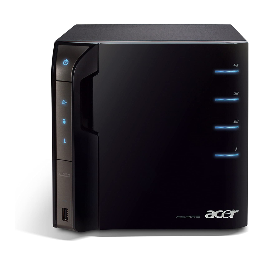
Page 10: System Tour
System Tour This section is a virtual tour of the system’s interior and exterior components. Front Panel Icon Component Power button/power indicator Network indicator Hard disk drive (HDD) status indicator System status indicator USB backup button/USB backup indicator USB 2.0 port Front door Open the door to access the hot-swappable HDDs. -
Page 11: Rear Panel
Rear Panel Icon Chapter 1 Component Recovery/reset button eSATA port Gigabit Ethernet port USB ports Power connector System fan... -
Page 12: Internal Components
Internal Components Component Backplane board Power supply Memory module Mainboard Chapter 1... -
Page 13: Front Panel
System LED Indicators Front panel This section describes the different system LED indicators. LED indicator Color Power Blue None Network Blue HDD status Purple None Chapter 1 LED status Description System is connected to the power supply and turned on and ready for use. - Page 14 LED indicator Color System status Blue Blue and purple USB device Blue backup HDD access Blue LED status Description Random blink • System is booting • System is shutting down System initialize operation completed. Random blink System is booting from a USB device (Reserved for BIOS update while boot block has been active) May indicate the following states: •...
- Page 15 Rear panel LED indicator Color LAN port Amber network speed Green None LAN port Green activity LED None Chapter 1 LED status Description 1000 Mbps network access 100 Mbps link network access 10 Mbps link network access Active network link Random blink Transmit or receive activity No network connection...
- Page 16 Chapter 1...
-
Page 17: System Utilities
System Utilities Phoenix BIOS Setup Utility BIOS setup is a hardware configuration program built into the system's Basic Input/Output System (BIOS). Since most systems are already properly configured and optimized, there is no need to run this utility. You will need to run this utility under the following conditions. -
Page 18: Entering Bios Setup
Entering BIOS setup IMPORTANT:To enter the BIOS setup, you need a debug board. Turn off the computer and all attached devices. Remove the cover. See “Removing the System Cover” on page 27. Connect the debug board cable to the debug board connector on the mainboard. Locate the JP3 Debug/User mode jumper on the mainboard. -
Page 19: Navigating Through The Setup Utility
Navigating Through the Setup Utility Use the following keys to move around the Setup utility. Left and Right arrow keys – Move between selections on the menu bar. Up and Down arrow keys – Move the cursor to the field you want. ... -
Page 20: Setup Utility Menus
Setup Utility Menus I n f o r m a t i o n C P U Ty p e : G e n u i n e I n t e l ® C P U 2 3 0 @ 1 . 6 0 G H z C P U S p e e d : 1 . - Page 21 Information The Information menu displays basic information about the system. These entries are for your reference only and are not user-configurable. I n f o r m a t i o n C P U Ty p e : G e n u i n e I n t e l ® C P U 2 3 0 @ 1 . 6 0 G H z C P U S p e e d : 1 .
- Page 22 Main I n f o r m a t i o n S y s t e m Ti m e : [ h h : m m : s s ] S y s t e m D a t e : [ m m / d d / y y y ] S ATA P O RT 0 S ATA P O RT 1 S ATA P O RT 2...
- Page 23 Advanced I n f o r m a t i o n S e t t i n g i t e m s o n t h i s m e n u t o i n c o r r e c t v a l u e s m a y c a u s e y o u r s y s t e m t o m a l f u n c t i o n .
-
Page 24: Hardware Monitor
Hardware Monitor The Hardware Monitor submenu displays options for measuring voltages and monitoring the system and processor temperature and fan speeds. I n f o r m a t i o n V + 1 . 5 = 5 V T R = V B AT = V + 5 = V c c p =... -
Page 25: Advanced Chipset Control
Advanced Chipset Control I n f o r m a t i o n I n t e g r a t e d D e v i c e C o n t r o l S u b - M e n u S e r i a l ATA : H e l p E s c... - Page 26 Boot The Boot menu allows you to set the drive priority during system boot-up. BIOS setup will display an error message if the drive specified is not bootable. I n f o r m a t i o n B o o t P r i o r i t y o r d e r : E x c l u d e d f r o m b o o t o r d e r H e l p E s c...
- Page 27 Exit The Exit menu displays the various options to quit from the BIOS setup. Highlight any of the exit options then press Enter. I n f o r m a t i o n E x i t S a v i n g C h a n g e s E x i t D i s c a r d i n g C h a n g e s L o a d S e t u p D e f a u l t s D i s c a r d C h a n g e s...
- Page 28 Chapter 2...
-
Page 29: System Disassembly
System Disassembly This chapter contains step-by-step procedures on how to disassemble the desktop computer for maintenance and troubleshooting. Disassembly Requirements To disassemble the computer, you need the following tools: Wrist grounding strap and conductive mat for preventing electrostatic discharge Flat-blade screwdriver ... -
Page 30: Pre-Disassembly Procedure
Pre-disassembly Procedure Before proceeding with the disassembly procedure, perform the steps listed below: Turn off the system and all the peripherals connected to it. Unplug the power cord from the power outlets. Unplug the power cord from the system. Unplug all peripheral cables from the system. Place the system unit on a flat, stable surface. -
Page 31: Main Unit Disassembly
Main Unit Disassembly MAIN UNIT DISASSEMBLY TURN OFF POWER HARD DISK DRIVE SYSTEM COVER FRONT I/O BRACKET BACKPLANE BOARD POWER SUPPLY HOUSING FRAME Screw List Chapter 3 DRIVE CARRIER MODULE HARD DISK DRIVE A x 3 FRONT BEZEL B x 4 FRONT I/O BOARD BACKPLANE BOARD BRACKET... -
Page 32: Removing The Hard Disk
Removing the Hard Disk Open the front panel. Press to release the hard drive carrier handle. Chapter 3... - Page 33 Flex the carrier handle. Slide the hard drive carrier out of the HDD bay. Chapter 3...
- Page 34 Remove the carrier by gently prying open the left rail of the carrier (1) and lift the hard disk off the carrier (2) . Chapter 3...
-
Page 35: Removing The System Cover
Removing the System Cover Perform the pre-disassembly procedure described on page 22. Remove the three screws (A) located on the rear panel. Screw (Quantity) M3-0.5*4 (3) Slide the system cover toward the back of the chassis until the tabs on the cover disengage with the slots on the chassis. -
Page 36: Removing The Front Bezel
Removing the Front Bezel Remove the system cover. Refer to the previous section for instructions. Release the front bezel retention tabs from the chassis interior. Pull the bezel slightly outward, then disconnect the front I/O board cable. Chapter 3... - Page 37 Pull the bezel away from the chassis. Chapter 3...
-
Page 38: Removing The Front I/O Board
Removing the Front I/O Board See “Removing the System Cover” on page 27. See “Removing the Front Bezel” on page 28. Remove the four screws (B) on the front I/O bracket. Screw (Quantity) M3*6L (4) Remove the bracket. Color Torque Silver 5.1 to 6.9 kgf-cm Part No. - Page 39 Remove the four screws (C) on the front I/O board. Screw (Quantity) M3*0.5*4L (4) Remove the front I/O board. Chapter 3 Color Torque Silver 5.1 to 6.9 kgf-cm Part No. 86.19534.4R0...
-
Page 40: Removing The Backplane Board
Removing the Backplane Board See “Removing the Hard Disk” on page 24. See “Removing the System Cover” on page 27. Disconnect the fan (1), LED (2), and power (3) cables from the backplane board. Disconnect the four HDD SATA cables from the mainboard. Chapter 3... - Page 41 Pull the backplane board bracket out of the chassis. Detach the four HDD SATA cables from the backplane board. Remove the seven screws (C) on the backplane board. Screw (Quantity) M3*0.5*4L (7) Chapter 3 Color Torque Silver 5.1 to 6.9 kgf-cm Part No.
- Page 42 Remove the backplane board from the bracket. Chapter 3...
-
Page 43: Removing The Power Supply
Removing the Power Supply See “Removing the Hard Disk” on page 24. See “Removing the System Cover” on page 27. See “Removing the Backplane Board” on page 32. Release the power cables from the cable ties, as shown. Disconnect the 4-pin power cable from the mainboard. Chapter 3... - Page 44 Remove the four screws (A) on the power supply. Screw (Quantity) M3-0.5*4 (4) With the thumb in the thumb hole, press the tab to release the mainboard carrier from the chassis. Color Torque Silver 5.1 to 6.9 kgf-cm Part No. 86.1A524.4R0 Chapter 3...
- Page 45 Slide the mainboard carrier out slightly, until you have access to the power cable. While pressing the tab on the 24-pin power cable, pull the cable off the connector on the mainboard. 10. Pull the power supply out of the chassis. Chapter 3...
-
Page 46: Removing The System Fan
Removing the System Fan See “Removing the Hard Disk” on page 24. See “Removing the System Cover” on page 27. See “Removing the Backplane Board” on page 32. Remove the four screws (A) that secures the system fan to the chassis. Screw (Quantity) M3-0.5*4 (3) Remove the system fan. -
Page 47: Removing The Memory Module
Removing the Memory Module See “Removing the Hard Disk” on page 24. See “Removing the System Cover” on page 27. See “Removing the Front Bezel” on page 28. See “Removing the Backplane Board” on page 32. See “Removing the Power Supply” on page 35. See “Removing the System Fan”... - Page 48 Press the holding clips on both sides of the DIMM slot outward to release the DIMM (1). 10. Gently pull the DIMM upward to remove it from the DIMM slot (2). Chapter 3...
-
Page 49: Removing The Mainboard
Removing the Mainboard See “Removing the Hard Disk” on page 24. See “Removing the System Cover” on page 27. See “Removing the Front Bezel” on page 28. See “Removing the Backplane Board” on page 32. See “Removing the Power Supply” on page 35. See “Removing the System Fan”... -
Page 50: Removing The Hdd Access Led Cables
Removing the HDD Access LED cables See “Removing the Hard Disk” on page 24. See “Removing the System Cover” on page 27. See “Removing the Front Bezel” on page 28. See “Removing the Backplane Board” on page 32. See “Removing the Power Supply” on page 35. See “Removing the System Fan”... -
Page 51: System Troubleshooting
This chapter provides instructions on how to troubleshoot system hardware problems. Hardware Diagnostic Procedure IMPORTANT:The diagnostic tests described in this chapter are only intended to test Acer products. Non-Acer products, prototype cards, or modified options can give false errors and invalid system responses. -
Page 52: H340 Diagnostics
H340 Diagnostics You can run the H340 diagnostics to determine whether the problems with the system are caused by failing hardware, such as system fan, LED board, hard disk drive, memory, etc. You must prepare a bootable USB device to run the tests on the system. To run the diagnostics, perform the following steps: Turn off the system. - Page 53 Test Items Boot from HDD 0 USB disk PQAF HDD test Read SN from DMI data check End test After all the tests are completed, the HDD LEDs light purple. A copy of the test result will be saved as a log file (i.e., 66380AC3.LOG) and stored in the Results folder. Chapter 4 HDD LED status (normal) HDD 1...
-
Page 54: System Check Procedures
Verify that components are properly seated. Verify that all cable connectors inside the system are firmly and correctly attached to their appropriate connectors. Verify that all components are Acer-qualified and supported. 10. Replace the system cover. 11. Power on the system. -
Page 55: Error Codes
Error Codes NOTE: Perform the FRU replacement or actions in the sequence shown in FRU/Action column, if the FRU replacement does not solve the problem, put the original part back in the computer. Do not replace a non-defective FRU. The error messages in the following table indicate the error signals on the HDD access LED indicators on the front panel and the error symptoms. -
Page 56: Online Support Information
This section describes online technical support services available to help you repair the system. If you are a distributor, dealer, ASP or TPM, please refer your technical queries to your local Acer branch office. Acer Branch Offices and Regional Business Units may access our website at http://global.acer.com/ support/index. -
Page 57: System Block Diagram And Board Layout
Chapter 5 System Block Diagram and Board Layout System Block Diagram Chapter 5... -
Page 58: Board Layout
Board Layout Mainboard Description SATA 3 port SATA 4 port SATA 2 port SATA 1 port USB ports Gigabit Ethernet port (top) USB ports (bottom) eSATA port Recovery/reset button Debug board connector Backplane board LED cable connector 4-pin power cable connector System fan cable connector (reserved) Processor Description... -
Page 59: System Jumpers
System Jumpers Name BIOS recovery jumper System type select jumper Debug/user mode jumper Chapter 5 Location Settings 1-2 Normal (default) 2-3 Clear CMOS 1-2 Aspire system (default) 2-3 Altos system Open User mode enabled (default) Closed Debug mode enabled... - Page 60 Chapter 5...
-
Page 61: Fru (Field Replaceable Unit) List
To scrap or to return the defective parts, follow the local government ordinance or regulations on how to dispose it properly, or follow the rules set by your regional Acer office on how to return it. This document will be updated as more information about the FRU list becomes available. -
Page 62: Exploded Diagram
Exploded Diagram Chapter 6... - Page 63 Item Part No. 42.60P02.001 42.60P03.001 34.60P07.001 34.60P05.001 34.60P04.001 47.60M06.001 42.60P01.001 40.60P04.001 40.60P03.001 41.60P02.001 42.55S13.001 42.91F07.001 42.5E309.001 50.60P04.001 33.60P09.001 33.60P05.001 30.60P02.001 86.1A524.4R0 60.60P14.001 86.1A524.4R0 60.60P11.001 33.60P04.001 60.60P02.001 45.00049.001 42.60P11.001 47.60P05.001 38.09008.001 40.60P07.001 60.60P03.001 40.60P06.001 42.60P17.001 42.60P16.001 Chapter 6 Part Name Handle HDD carrier HT-361 Latch HDD carrier HT-361 Axis HDD carrier HT-361 SPG HDD carrier HT-361...
-
Page 64: Fru List
CORD SVT 10A 125V 1800MM BLK CORD VCTF 3G 7A/125V(JAPAN) CORD 250V 10A 1800MM SWISS C.A. CAT5E STRAI BLACK_2M BIZ BRKT FRONT I/O HT-361 BRKT PSU SUPPORT HT-361 ASSY ASPIRE BEZEL HT-361 HOUSING ASSY HT-361 Acer Description Part Number 55.R3601.002 55.R3601.001 50.R3601.001 50.R3601.003 50.R3601.002 50.R3601.004... - Page 65 ASSY MB TRAY HT-361 CAS UP HT-361 DK103-KY05 MASTER KEY HT-361 ASSY FAN 120X120X25 S15 HDD 1TB SGT ST31000333AS 7.2KR HDD 640GB 3.5" SGT ST3640623AS S15I MAIN BOARD W/O CPU,DIMM Acer Description Part Number 33.R3601.001 42.R3601.001 33.R3601.004 23.R3601.001 KH.01K01.005 KH.64001.001...
- Page 66 Part Name DIMM 1G GU341G0ALEPR6B2C6CE DIMM 1G GU341G0ALEPR6B2C6CE SPS 200W 1U DELTA GPS-200AB B SCRW TAP PAN M3*6L 2LEAD NI SCRW MACH P/WS M3*0.5*4L NI SCRW MACH PAN M3-0.5*4 NI Acer Description Part Number KN.51203.034 KN.1GB0H.009 PY.20009.001 86.VA524.6R0 86.19534.4R0 86.1A524.4R0...
-
Page 67: Technical Specifications
Technical Specifications This section provides technical specifications for the system. Processor Item Specification Type Onboard Intel Atom 200 series Model number Atom 230 Frequency (MHz) 1600 L2 cache size (KB) Socket type Micro-FCBGA Stepping Manufacturing tech 90 nm SOl (CMOS) Wattage (W) System bus (MHz) System Board Major Chips... - Page 68 System Memory Item Memory type Organization Pin count DIMM sockets DIMM size Minimum memory Maximum memory Vendor Model name System BIOS Item BIOS vendor BIOS version Flash memory PCI Interface Item PCI Express controller Number of slots Network Interface Item LAN controller Supports LAN protocol LAN connector type...