Siemens SITRANS LG240 Operating Instructions Manual
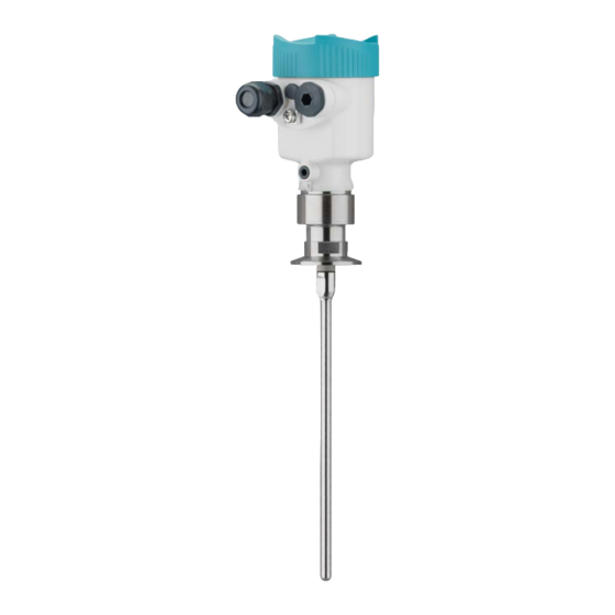
Guided wave radar, 4…20 ma/hart - two-wire polished rod probe
Hide thumbs
Also See for SITRANS LG240:
- Operating instructions manual (88 pages) ,
- Operating instructions manual (80 pages)

Related Manuals for Siemens SITRANS LG240


Summary of Contents for Siemens SITRANS LG240
- Page 1 Guided Wave Radar SITRANS LG240 4 … 20 mA/HART - two-wire Polished rod probe Operating Instructions • 09/2017...
- Page 2 SITRANS LG240 - Operating Instructions PBD-51041038...
-
Page 3: Table Of Contents
Saving the parameterisation data ................... 52 Set up with other systems ....................53 DD adjustment programs ....................53 Field Communicator 375, 475 ..................53 Diagnostics and servicing ....................54 Maintenance ........................54 Diagnosis memory ......................54 PBD-51041038 SITRANS LG240 - Operating Instructions... - Page 4 11.2 Dimensions ........................77 11.3 Trademark ........................82 Safety instructions for Ex areas Take note of the Ex specific safety instructions for Ex applications. These instructions are attached as documents to each instrument with Ex approval and are part of the operating instructions manual. Editing status: 2017-09-14 SITRANS LG240 - Operating Instructions PBD-51041038...
-
Page 5: About This Document
This arrow indicates a single action. Sequence of actions Numbers set in front indicate successive steps in a procedure. Battery disposal This symbol indicates special information about the disposal of bat- teries and accumulators. PBD-51041038 SITRANS LG240 - Operating Instructions... -
Page 6: For Your Safety
During work on and with the device the required personal protective equipment must always be worn. Appropriate use SITRANS LG240 is a sensor for continuous level measurement. You can find detailed information about the area of application in chapter "Product description". Operational reliability is ensured only if the instrument is properly used according to the specifications in the operating instructions manual as well as possible supplementary instructions. -
Page 7: Eu Conformity
National Electrical Code (ANSI/NFPA 70). Installations in Canada shall comply with the relevant requirements of the Canadian Electrical Code A Class 2 power supply unit has to be used for the installation in the USA and Canada. PBD-51041038 SITRANS LG240 - Operating Instructions... -
Page 8: Product Description
Scope of delivery The scope of delivery encompasses: • Sensor • Optional accessory • Documentation – Operating instructions SITRANS LG240 – Instructions for optional instrument features – Ex-specific "Safety instructions" (with Ex versions) – If necessary, further certificates SITRANS LG240 - Operating Instructions PBD-51041038... -
Page 9: Principle Of Operation
Principle of operation Application area The SITRANS LG240 is a level sensor with polished rod probe for continuous level or interface measurement, particularly suitable for applications in the food processing and pharmaceutical industry. Optionally an autoclaved version with separable housing is available. - Page 10 Example: upper medium dielectric constant 2, lower medium at least dielectric constant 12. Gas phase (L3) • Air or gas mixture • Gas phase - dependent on the application, gas phase does not always exist (d2 = 0) SITRANS LG240 - Operating Instructions PBD-51041038...
-
Page 11: Packaging, Transport And Storage
"LG Local Display Interface" (Document-ID 43838). External display and The LG Remote Interface is an external display and adjustment unit adjustment unit for sensors with single chamber housing and Ex-d double chamber housing. PBD-51041038 SITRANS LG240 - Operating Instructions... - Page 12 You can find further information in the operating instructions manual "Electronics module SITRANS series LG". Centering If you mount the SITRANS LG240 in a bypass tube or standpipe, you have to avoid contact to the bypass tube by using a spacer at the probe end. You can find additional information in the operating instructions manual "Centering".
-
Page 13: Mounting
• Process fitting • Process seal Process conditions in particular are: • Process pressure • Process temperature • Chemical properties of the medium • Abrasion and mechanical influences You can find detailed information on the process conditions in chapter "Technical data" as well as on the type label. PBD-51041038 SITRANS LG240 - Operating Instructions... -
Page 14: Mounting Instructions
Mounting instructions Installation position Mount SITRANS LG240 in such a way that the distance to vessel installations or to the vessel wall is at least 300 mm (12 in). In non- metallic vessels, the distance to the vessel wall should be at least 500 mm (19.7 in). - Page 15 In such cases, always carry out a false signal suppression after mounting. You can find further information under "Setup procedure". ≤ 150 mm ( 5.91") DN25 ... DN150 > DN150 ... DN200 ≤ 100 mm ( 3.94") Fig. 6: Mounting socket When welding the socket, make sure that the socket is flush with the vessel top. PBD-51041038 SITRANS LG240 - Operating Instructions...
- Page 16 - measurement in these areas is not possible (dead band). The length of the cable can be used all the way to the end only when measuring conductive SITRANS LG240 - Operating Instructions PBD-51041038...
- Page 17 For this, use an additional plastic sleeve (PTFE, PPS, PEEK etc.), to protect the probe against damages. Keep in mind that measurement is not possible below the fastening point. Fig. 9: Fasten the probe Measuring probe Retaining sleeve Plastic sleeve (PTFE, PPS, PEEK etc.) PBD-51041038 SITRANS LG240 - Operating Instructions...
- Page 18 Screw the enclosed lid with slotted nut onto the instrument side of the process fitting and tighten the nut with a torque of 20 Nm. Make sure that no liquid or contamination penetrates into the housing or the process side. After autoclaving, screw the lid off again and place the housing verti- cally on the side of the process fitting. Tighten the slotted nut with a torque of 20 Nm. SITRANS LG240 - Operating Instructions PBD-51041038...
- Page 19 DIN DN25 DN32 DN40 / 1" 1 1/2" ø 50,5 DIN DN50 / 2" ø 64 DIN DN65 / 3" ø 91 Fig. 10: Autoclaved version Groove nut 2 Process fitting Cover with groove nut PBD-51041038 SITRANS LG240 - Operating Instructions...
-
Page 20: Connecting To Power Supply
Prior to setup you have to replace these protective caps with ap- proved cable glands or close the openings with suitable blind plugs. SITRANS LG240 - Operating Instructions PBD-51041038... -
Page 21: Connecting
4. Remove approx. 10 cm (4 in) of the cable mantle, strip approx. 1 cm (0.4 in) of insulation from the ends of the individual wires 5. Insert the cable into the sensor through the cable entry PBD-51041038 SITRANS LG240 - Operating Instructions... - Page 22 When the screwdriver is released, the terminal closes again. You can find further information on the max. wire cross-section under "Technical data - Electromechanical data". 7. Check the hold of the wires in the terminals by lightly pulling on them SITRANS LG240 - Operating Instructions PBD-51041038...
-
Page 23: Wiring Plan, Single Chamber Housing
The following illustrations apply to the non-Ex as well as to the Ex-ia version. Electronics compartment 4...20mA 6 7 8 Fig. 14: Electronics compartment - double chamber housing Internal connection to the terminal compartment For display and adjustment module or interface adapter PBD-51041038 SITRANS LG240 - Operating Instructions... -
Page 24: Wiring Plan, Ex-D-Ia Double Chamber Housing
For display and adjustment module or interface adapter Internal connection to the plug connector for external display and adjust- ment unit (optional) Note: HART multidrop mode is not possible when using an Ex-d-ia instru- ment. SITRANS LG240 - Operating Instructions PBD-51041038... -
Page 25: Supplementary Electronics
PC • Indication of the status message "F 105 Determine measured value" on the display or PC • The output signal jumps to the set fault current PBD-51041038 SITRANS LG240 - Operating Instructions... - Page 26 As soon as a plausible measured value is found, the corresponding current is outputted to the signal cable. The value corresponds to the actual level as well as the settings already carried out, e.g. factory setting. SITRANS LG240 - Operating Instructions PBD-51041038...
-
Page 27: Set Up With The Display And Adjustment Module
Fig. 19: Insertion of the display and adjustment module with single chamber housing Note: If you intend to retrofit the instrument with a display and adjustment module for continuous measured value indication, a higher lid with an inspection glass is required. PBD-51041038 SITRANS LG240 - Operating Instructions... -
Page 28: Adjustment System
5 s, the display returns to the main menu. The menu language is then switched over to "English". Approx. 60 minutes after the last pressing of a key, an automatic reset to measured value indication is triggered. Any values not confirmed with [OK] will not be saved. SITRANS LG240 - Operating Instructions PBD-51041038... -
Page 29: Parameter Adjustment - Quick Setup
Switch-on phase After switching on, the SITRANS LG240 carries out a short self-test where the device software is checked. The output signal transmits a fault signal during the switch-on phase. The following information is displayed on the display and adjustment module during the startup procedure: •... - Page 30 "->" key you jump to the next position. You can enter names with max. 19 characters. The character set comprises: • Capital letters from A … Z • Numbers from 0 … 9 • Special characters + - / _ blanks SITRANS LG240 - Operating Instructions PBD-51041038...
- Page 31 In this menu item, you can define the type of medium (product). Setup - Application - Me- dium, dielectric constant This menu item is only available if you have selected level measure- ment under the menu item "Application". PBD-51041038 SITRANS LG240 - Operating Instructions...
- Page 32 In this menu item you can enter the max. adjustment for the level. With Level interface measurement this is the maximum total level. Adjust the requested percentage value with [+] and store with [OK]. SITRANS LG240 - Operating Instructions PBD-51041038...
- Page 33 As an alternative, you have the possibility taking over the adjustment of the level measurement also for the interface. Enter the respective distance value in m for the surface of the upper medium corresponding to the percentage value. PBD-51041038 SITRANS LG240 - Operating Instructions...
- Page 34 In the following, you have to enter the values for your vessel, for example the vessel height and the socket correction. SITRANS LG240 - Operating Instructions PBD-51041038...
- Page 35 In the menu item "Current output mode" you determine the output mode characteristics and reaction of the current output in case of fault. The default setting is output characteristics 4 … 20 mA, fault mode < 3.6 mA. PBD-51041038 SITRANS LG240 - Operating Instructions...
- Page 36 The level would then no longer be detectable in this area. If a false signal suppression has already been created in the sensor, the following menu window appears when selecting "False signal suppression": SITRANS LG240 - Operating Instructions PBD-51041038...
- Page 37 The following submenu points are available: The submenu points are described below. Display - Menu language This menu item enables the setting of the requested national lan- guage. PBD-51041038 SITRANS LG240 - Operating Instructions...
- Page 38 In delivery status, the lighting is switched on. Diagnostics - Device In this menu item, the device status is displayed. status When the instrument displays a failure message, you can here get detailed information on the failure reason. SITRANS LG240 - Operating Instructions PBD-51041038...
- Page 39 The respective min. and max. measured values are saved in the ues, Additional sensor. The values are displayed in the menu item "Peak values Ad- ditional". This menu item displays the peak values of the electronics tempera- ture as well as the dielectric constant. PBD-51041038 SITRANS LG240 - Operating Instructions...
- Page 40 Select the requested simulation variable and set the requested value. Caution: During simulation, the simulated value is outputted as 4 … 20 mA cur- rent value and digital HART signal. SITRANS LG240 - Operating Instructions PBD-51041038...
- Page 41 In this menu item, the internal clock of the sensor is set. Time After a reset, certain parameter adjustments made by the user are Additional settings - Reset reset. Note: After this menu window, the reset process is carried out. No further safety inquiry follows. PBD-51041038 SITRANS LG240 - Operating Instructions...
- Page 42 Distance: Probe length - take dead band into account Max. adjustment - Interface 100 % Distance: 0.000 m(d) - note block- ing distances Min. adjustment - Interface Distance: Probe length - take dead band into account SITRANS LG240 - Operating Instructions PBD-51041038...
- Page 43 20.5 mA Menu - Display Menu Menu item Default value Display Language Selected language Displayed value 1 Filling height Displayed value 2 Electronics temperature Display format 1 Automatically Display format 2 Automatically Backlight Switched on PBD-51041038 SITRANS LG240 - Operating Instructions...
- Page 44 We recommend to save the instrument adjustments. In case of an electronics exchange the saved parameter adjustment data relieve this process. Additional settings - Scal- Since scaling is very extensive, scaling of the level value was divided ing level into two menu items. SITRANS LG240 - Operating Instructions PBD-51041038...
- Page 45 0 % and format 100 %. Additional settings - Cur- Since scaling is very extensive, scaling of the level value was divided rent output into two menu items. PBD-51041038 SITRANS LG240 - Operating Instructions...
- Page 46 The default setting is "Analogue current output" and the address 00. Additional settings - Spe- In this menu item you gain access to the protected area where cial parameters you can enter special parameters. In exceptional cases, individual parameters can be modified in order to adapt the sensor to special requirements. SITRANS LG240 - Operating Instructions PBD-51041038...
-
Page 47: Saving The Parameterisation Data
The following data or settings for adjustment of the display and ad- justment module are saved: • All data of the menu "Setup" and "Display" • The items "Sensor-specific units, temperature unit and linearisa- tion" in the menu "Additional settings". PBD-51041038 SITRANS LG240 - Operating Instructions... - Page 48 If it is necessary to exchange a sensor, the display and adjustment module is inserted into the replacement instrument and the data are likewise written into the sensor via the menu item "Copy device settings". SITRANS LG240 - Operating Instructions PBD-51041038...
-
Page 49: Setup With Pactware
USB cable to the PC Interface adapter Sensor Connection via HART Fig. 23: Connecting the PC via HART to the signal cable Sensor 2 HART resistance 250 Ω (optional depending on evaluation) Adapter cable for HART modem Processing system/PLC/Voltage supply HART modem PBD-51041038 SITRANS LG240 - Operating Instructions... -
Page 50: Parameter Adjustment With Pactware
Furthermore a tank calculation program as well as a multiviewer for indication and analysis of the saved measured value and echo curves are available. The supplied DVD includes the respective device DTM. How- ever, you can also download the DTM from our homepage www.siemens.com/sitranslg. SITRANS LG240 - Operating Instructions PBD-51041038... -
Page 51: Set Up With The Quick Setup
Extended adjustment Maintenance Quick setup With quick setup you can carry out the parameter adjustment of SITRANS LG240 for your application in just a few simple steps. The assistant-driven adjustment includes the basic settings for simple, reliable setup and commissioning. Information: If the function is inactive, then possibly no instrument is connected. -
Page 52: Saving The Parameterisation Data
Click to the button "Quick setup", to start the assistant-driven adjust- ment for a simplified and reliable setup. Saving the parameterisation data We recommend documenting or saving the parameterisation data via PACTware. That way the data are available for multiple use or service purposes. SITRANS LG240 - Operating Instructions PBD-51041038... -
Page 53: Set Up With Other Systems
This software is updated via the Internet and new EDDs are automatically accepted into the device catalogue of this software after they are released by the manufacturer. They can then be transferred to a Field Communicator. PBD-51041038 SITRANS LG240 - Operating Instructions... -
Page 54: Diagnostics And Servicing
Echo curve of the setup: This is used as reference echo curve for the measurement conditions during setup. Changes in the measure- ment conditions during operation or buildup on the sensor can thus be recognized. The echo curve of the setup is stored via: • PC with PACTware/DTM • Control system with EDD SITRANS LG240 - Operating Instructions PBD-51041038... -
Page 55: Status Messages
This status message is inactive by default. It can be activated by the user via PACTware/DTM or EDD. Maintenance: Due to external influences, the instrument function is limited. The measurement is affected, but the measured value is still valid. Plan in maintenance for the instrument because a failure is expected in the near future (e.g. due to buildup). PBD-51041038 SITRANS LG240 - Operating Instructions... - Page 56 Error during setup Carry out a reset Bit 9 of Byte 0 … 5 • • Error when carrying out a Repeat setup Error in the reset instrument • False signal suppression settings faulty SITRANS LG240 - Operating Instructions PBD-51041038...
- Page 57 • Use coaxial probe • • S602 Compensation echo super- 100 % adjustment: Increase Bit 10 of Byte 14 … 24 imposed by medium value Level with- in the search range, com- pensation echo PBD-51041038 SITRANS LG240 - Operating Instructions...
-
Page 58: Rectify Faults
The operator of the system is responsible for taking suitable meas- tion occurs ures to rectify faults. Procedure for fault recti- The first measures are: fication • Evaluation of fault messages via the adjustment device • Checking the output signal • Treatment of measurement errors SITRANS LG240 - Operating Instructions PBD-51041038... - Page 59 Wherever the sensor displays a constant value, the reason could also be the fault setting of the current output to "Hold value" • If the level indication is too low, the reason could be a line resist- ance that is too high PBD-51041038 SITRANS LG240 - Operating Instructions...
- Page 60 • 0 m distance signals in the close range. The Check installation conditions • sensor goes into overfill protec- If possible, switch off the func- tion mode. The max. level (0 m tion "Overfill protection" time distance) as well as the status message "Overfill protection" are outputted. SITRANS LG240 - Operating Instructions PBD-51041038...
-
Page 61: Exchanging The Electronics Module
Exchanging the rod Exchanging the rod The rod (meas. part) of the probe can be exchanged, if necessary. To loosen the meas. rod you need a fork spanner with spanner width 10. PBD-51041038 SITRANS LG240 - Operating Instructions... -
Page 62: Exchanging The Seal
(see "Setup procedure, Carry- ing out min. adjustment - Carrying out max. adjustment"). Exchanging the seal Exchanging the seal If necessary, the seal of the probe can be exchanged. SITRANS LG240 - Operating Instructions PBD-51041038... - Page 63 Use special tools in order to avoid damag- ing the surface. 1. Loosen the rod by applying a fork spanner to the flat surfaces (SW 10), provide counterforce manually on the process fitting 2. Screw out the loosened measuring rod by hand 3. Push the enclosed new seal ring (9.25 x 1.78) onto the thread of the measuring rod. PBD-51041038 SITRANS LG240 - Operating Instructions...
- Page 64 Fig. 37: Exchanging the measuring rod Sealing ring (9.25 x 1.78) 4. Loosen process fitting with a suitable wrench. 5. Unscrew the process fitting manually from the sensor. 6. Remove the old seal out of the process fitting. 7. Insert the attached new seal ring (15.54 x 2.62) into the process fitting. SITRANS LG240 - Operating Instructions PBD-51041038...
-
Page 65: Software Update
4.5 Nm (3.32 lbf ft). Information: Please maintain the specified torque so that the max. tensile strength of the connection remains. Software update The following components are required to update the sensor soft- ware: • Sensor • Voltage supply • PC with PACTware • Current sensor software as file PBD-51041038 SITRANS LG240 - Operating Instructions... -
Page 66: How To Proceed If A Repair Is Necessary
Instruments with approvals can be bound to certain software versions. Therefore make sure that the approval is still effective after a software update is carried out. You can find detailed information in the download area on our home- page: www.siemens.com/sitranslg. How to proceed if a repair is necessary If it is necessary to repair the instrument, please contact Sie- mens Milltronics Process Instruments. You find the locations on "www.siemens.com/sitranslg". SITRANS LG240 - Operating Instructions PBD-51041038... -
Page 67: Dismount
Pass the instrument directly on to a spe- cialised recycling company and do not use the municipal collecting points. These may be used only for privately used products according to the WEEE directive. PBD-51041038 SITRANS LG240 - Operating Instructions... -
Page 68: Supplement
Ʋ Rod: ø 8 mm (0.315 in) - polished up to 4 m (13.12 ft) - also possible for segmented rods Ʋ Trimming accuracy - rod ±1 mm + 0.05 % of the rod length All wetted parts. SITRANS LG240 - Operating Instructions PBD-51041038... - Page 69 3.8 … 20.5 mA (default setting) Signal resolution 0.3 µA Fault signal, current output (adjustable) Last valid measured value, ≥ 21 mA, ≤ 3.6 mA Max. output current 21.5 mA The output values can be assigned individually. The indication values can be assigned individually. PBD-51041038 SITRANS LG240 - Operating Instructions...
- Page 70 Water/Oil (dielectric constant ~2.0) Ʋ Mounting Probe end does not touch the vessel bottom Sensor parameter adjustment No gating out of false signals carried out The indication values can be assigned individually. With interface measurement = 2.0 SITRANS LG240 - Operating Instructions PBD-51041038...
- Page 71 Fig. 39: Measuring ranges - SITRANS LG240 Reference plane Probe length L Measuring range (default setting refers to the measuring range in water) Upper dead band (see following diagrams - grey section) Lower dead band (see following diagrams - grey section) Typical deviation - Interface measure- ±...
- Page 72 0,08 m 0,2 m 0,04 m (3.15 (7.874 " " (1.575 ") Fig. 40: Deviation SITRANS LG240 in rod version in water Dead band (no measurement possible in this area) Probe length 15 mm (0.591 " 2 mm (0.079 ") -2 mm (-0.079...
- Page 73 -40 … +80 °C (-40 … +176 °F) ture Also for the additional current output (optional). Time span after a sudden measuring distance change by max. 0.5 m in liquid applications, max 2 m with bulk solids applications, until the output signal has taken for the first time 90 % of the final value (IEC 61298-2). PBD-51041038 SITRANS LG240 - Operating Instructions...
- Page 74 Stainless steel housing, precision casting Stainless steel housing, electropolished SIP process temperature (SIP=Sterilization in place) Seals suitable for vapour: FFKM (Kalrez 6621) or EPDM (Freudenberg 70 EPDM 291) Vapour stratification up to 2 h +150 °C (+302 F) Mechanical stress Vibration resistance Ʋ Rod probe 1 g with 5 … 200 Hz according EN 60068-2-6 (vibration at resonance) with rod length 50 cm (19.69 in) SITRANS LG240 - Operating Instructions PBD-51041038...
- Page 75 Via the display and adjustment module Ʋ Analogue Via the current output Ʋ Digital Via the digital output signal (depending on the electron- ics version) Range -40 … +85 °C (-40 … +185 °F) PBD-51041038 SITRANS LG240 - Operating Instructions...
- Page 76 IP 66/IP 68 (0.2 bar) Type 6P Double chamber IP 66/IP 67 Type 4X IP 66/IP 68 (0.2 bar) Type 6P Stainless steel, electro- Single chamber IP 66/IP 68 (0.2 bar) Type 6P polished SITRANS LG240 - Operating Instructions PBD-51041038...
-
Page 77: Dimensions
½ NPT Fig. 43: Housing versions with protection rating IP 66/IP 67 - with integrated display and adjustment module the housing is 9 mm/0.35 in higher Plastic single chamber Plastic double chamber When used with fulfilled housing protection IEC 61010-1 PBD-51041038 SITRANS LG240 - Operating Instructions... - Page 78 Fig. 45: Housing versions with protection rating IP 66/IP 68 (0.2 bar) - with integrated display and adjustment module the housing is 9 mm/0.35 in higher Stainless steel single chamber (electropolished) Stainless steel single chamber (precision casting) Stainless steel double chamber housing (precision casting) SITRANS LG240 - Operating Instructions PBD-51041038...
- Page 79 SITRANS LG240, rod version ø 8 mm (0.315 in), polished ø 8 mm (0.32") Fig. 46: SITRANS LG240, rod version ø 8 mm (0.315 in), polished Sensor length, see chapter "Technical data" PBD-51041038 SITRANS LG240 - Operating Instructions...
- Page 80 ø 50,5 DIN DN50 / 2" ø 64 DIN DN65 / 3" ø 91 Fig. 47: SITRANS LG240, rod version ø 8 mm (0.315 in), polished - autoclaved version Compression nut Process fitting Cover lid SITRANS LG240 - Operating Instructions PBD-51041038...
- Page 81 1 Version with threaded fitting 2 Version with flange connection A Basic extension rod with ø 8 mm (0.315 in) B Extension rod with ø 8 mm (0.315 in) C End rod with ø 8 mm (0.315 in) Length (order length) PBD-51041038 SITRANS LG240 - Operating Instructions...
-
Page 82: Trademark
11.3 Trademark All the brands as well as trade and company names used are property of their lawful proprietor/ originator. SITRANS LG240 - Operating Instructions PBD-51041038... - Page 83 Electronics compartment - double chamber Read out info 47 housing 23 Repair 66 Error codes 57 Replacement parts Event memory 54 – Electronics module 12 – Rod components 12 – Spacer 12 Factory calibration date 47 Reset 41 PBD-51041038 SITRANS LG240 - Operating Instructions...
- Page 84 Scaling measured value 44, 45 Sensor characteristics 47 Sensor status 38 Simulation 40 Special parameters 46 Type label 8 Type of medium 31 Units 31 SITRANS LG240 - Operating Instructions PBD-51041038...
- Page 85 Notes PBD-51041038 SITRANS LG240 - Operating Instructions...
- Page 86 Notes SITRANS LG240 - Operating Instructions PBD-51041038...
- Page 87 Notes PBD-51041038 SITRANS LG240 - Operating Instructions...
- Page 88 For more information www.siemens.com/level www.siemens.com/weighing Siemens Canada Limited Subject to change without prior notice PD PA PI LW PBD-51041038 Rev. 6.0 1954 Technology Drive P.O. Box 4225 © Siemens AG 2017 Peterborough, ON K9J 7B1, Canada email: [email protected] Printed in Canada www.siemens.com/processautomation...