Table of Contents
Quick Links
10/100/1000M
Industrial Switching HUB
NZ2EHG-T8N
User's Manual
Powered by CONTEC
This product was jointly developed and manufactured by Mitsubishi and
CONTEC.
Note that some of the warranty on this product differs from that on other
products (MELSEC iQ-R/Q/L series).
(Refer to "Terms of Warranty".)
© 2 0 1 6 M I T S U B I S H I E L E C T R I C C O R P O R A T I O N
MODEL
MODEL
CODE
IB(NA)-0800554-B(2108)MEE
NZ2EHG-T8N-U
13J026
Table of Contents

Related Manuals for Mitsubishi Electric NZ2EHG-T8N


Summary of Contents for Mitsubishi Electric NZ2EHG-T8N
- Page 1 10/100/1000M Industrial Switching HUB NZ2EHG-T8N User’s Manual Powered by CONTEC This product was jointly developed and manufactured by Mitsubishi and CONTEC. Note that some of the warranty on this product differs from that on other products (MELSEC iQ-R/Q/L series). (Refer to "Terms of Warranty”.)
-
Page 2
Mitsubishi shall mainly replace products that need repair. It may take some time to respond to the problem or repair the product depending on the condition and timing.
General specifications are different. NZ2EHG-T8N MELSEC-Q Series Operating ambient temperature 0 to 50°C 0 to 55°C... - Page 3 Safety Precautions Review the following definitions and precautions to use the product safely. Safety Information This document provides safety information using the following symbols to prevent accidents resulting in injury or death and the destruction of equipment and resources. Review the meanings of these labels to operate the equipment safely.
- Page 4 Do not use or store the product in a hot or cold place, or in a place that is subject to severe temperature changes. Doing so may cause malfunction, heat generation, fault, or damage. Do not use or store the product in a place subject to direct sunlight or near a heating device, such as a stove. And do not use or store the product near equipment generating a strong magnetic field or radio waves.
- Page 5 CONDITIONS OF USE FOR THE PRODUCT Mitsubishi programmable controller ("the PRODUCT") shall be used in conditions; i) where any problem, fault or failure occurring in the PRODUCT, if any, shall not lead to any major or serious accident; and ii) where the backup and fail-safe function are systematically or automatically provided outside of the PRODUCT for the case of any problem, fault or failure occurring in the PRODUCT.
-
Page 6: Packing List
Thank you for purchasing this Mitsubishi product. The product package contains the items listed below. Check the contents of the product package. If you discover any damaged or missing items, contact the distributor. Contents Name Pcs. Industrial switching HUB unit (NZ2EHG-T8N) User’s Manual Power terminal connector Retention bracket Mounting bracket Bracket screw M3x6... -
Page 7: Table Of Contents
Table of Contents Packing List ............................5 1. Before Using the Product About the Unit ............................. 7 Features ............................7 Environment ..........................8 Inspection ............................. 8 Storage ............................8 Disposal ............................8 2. Part Names and Settings Part Names and Functions ........................9 3. -
Page 8: Before Using The Product
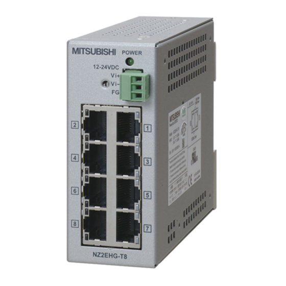
1. Before Using the Product This chapter provides information you should know before using the product. About the Unit NZ2EHG-T8N is a compact-sized [39(W) × 120(D) × 94(H) mm] industrial switching HUB unit that is compliant with the IEEE802.3ab (1000BASE-T)/IEEE802.3u (100BASE-TX)/IEEE802.3 (10BASE-T) standards. -
Page 9: Environment
- The ventilation slits are not covered, and neither dust nor alien substance is attached to the ventilation slits. POWER 12-24VDC NZ2EHG-T8N Storage When storing this product, keep it in its original packing form. (1) Put the unit in the storage bag. -
Page 10: Part Names And Settings
12-24VDC Power supply connector (FG) LED : A LED : A LED : B LED : B 10BASE-T/100BASE-TX/ 1000BASE- T port NZ2EHG-T8N Figure 2.1. Part names Table 2.1. LED indicators Name Status Color Display POWER LED POWER Green OFF : Power off... - Page 11 2 . P a r t N a m e s a n d S e t t i n g s Table 2.3. 10BASE-T/100BASE-TX/1000BASE-T port Name Function 10BASE-T/ Ports 1 to 8 100BASE-TX/ Use these ports to connect personal computers, additional HUB units, bridges, 1000BASE-T port or other devices.
-
Page 12: Setup Of Hardware
3. Setup of Hardware 3. Setup of Hardware Mounting/Removing a Unit on/from a DIN Rail Mounting Procedure (1) Hook the upper clips of a DIN rail mounting bracket to the upper groove of a DIN rail, and then push the lower part of the unit to the DIN rail. Figure 3.1. -
Page 13: Removing Procedure
3. Setup of Hardware Removing Procedure A phillips-head screwdriver or a flathead screwdriver is required to remove a unit from a DIN rail. CAUTION Disconnect LAN cables and power cables connected to the unit before removing from the DIN rail. For a Phillips-head screwdriver (1) Insert a phillips-head screwdriver (diameter: 6 to 7mm) into the latch metal fitting on the lower part of the unit. - Page 14 3. Setup of Hardware (3) By lifting the unit, you can easily remove it from the DIN rail. Figure 3.2. Removing a unit from a DIN rail with a phillips-head screwdriver < 3 / 3 > For a flathead screwdriver (1) Insert a flathead screwdriver (tooth width 5.5 to 7mm) into the latch metal fitting on the lower part of the unit, and push the tip of the screwdriver down vertically.
-
Page 15: Attaching Mounting Brackets
3. Setup of Hardware (3) By lifting the unit, you can easily remove it from the DIN rail. Figure 3.3. Removing a unit from a DIN rail with a flathead screwdriver < 3 / 3 > Attaching mounting brackets Attachment Remove the four screws and separate the DIN rail mounting bracket from the unit. -
Page 16: Attaching A Retention Bracket
3. Setup of Hardware Attaching a retention bracket Attachment (1) Plug in the power terminal connector to the power connector and attach the retention bracket using a bracket screw. 1 2 -2 1 2 -2 - T 8 - T 8 Figure 3.6. -
Page 17: Installation Conditions
3 . S e t u p o f H a r d w a r e Installation Conditions CAUTION W h e n u s e d i n a p p l i c a t i o n s w i t h h i g h e n v i r o n m e n t a l t e m p e r a t u r e s , e v e n i f t h e u n i t i s o p e r a t e d w i t h i n t h e t e m p e r a t u r e r a n g e s p e c i f i c a t i o n , m a k e s u r e t h a t h e a t g e n e r a t e d b y t h e u n i t h a s a n a d e q u a t e d i s s i p a t i o n p a t h . - Page 18 3 . S e t u p o f H a r d w a r e W h e n m o u n t i n g b r a c k e t s a r e u s e d I n s t a l l a t i o n i n a n y o r i e n t a t i o n i s p o s s i b l e .
-
Page 19: Spacing Between Unit And Surrounding Objects
3 . S e t u p o f H a r d w a r e Spacing between Unit and Surrounding Objects CAUTION D o n o t i n s t a l l t h e u n i t i n a s e a l e d h o u s i n g . W h e n i n s t a l l e d u s i n g a D I N r a i l m o u n t i n g b r a c k e t E n s u r e t h e d i s t a n c e b e t w e e n t h e u n i t a n d a n y s u r r o u n d i n g o b j e c t s a s f o l l o w s : A b o v e a n d b e l o w t h e u n i t : 5 0 m m o r m o r e... - Page 20 3 . S e t u p o f H a r d w a r e W h e n i n s t a l l e d u s i n g m o u n t i n g b r a c k e t s E n s u r e t h e d i s t a n c e b e t w e e n t h e u n i t a n d a n y s u r r o u n d i n g o b j e c t s a s f o l l o w s : A b o v e a n d b e l o w t h e u n i t : 5 0 m m o r m o r e U n d e r t h e r a t i n g p l a t e s i d e o f t h e u n i t : 5 .
-
Page 21: Connecting To A Network
CAUTION To use Jumbo Frame, it is necessary for other network devices of the communication target, such as LAN adapters, to be Jumbo Frame compatible. NZ2EHG-T8N Q06UDEHCPU .,etc Straight or cross cables Figure 4.1. Connection example... -
Page 22: Connection Restrictions For 100Base-Tx Repeater Hubs
Class II 100BASE-TX repeater HUBs. In addition, the maximum total length of cables (1) (2) (3) is 205m or less. For details, refer to the user's manual for the 100BASE- TX repeater HUB used. NZ2EHG-T8N 100BASE-T X HUB 100BASE-T X HUB... -
Page 23: System Reference
5. System Reference 5. System Reference Specifications Table 5.1. Specifications Item Specifications Ethernet standards IEEE802.3/IEEE802.3u /IEEE802.3ab –compliant Data communication rate 10/100/1000Mbps (auto-recognition) Access method CSMA/CD Communication method All ports: Full/Half duplex (auto-recognition) Topology Star topology Flow control Full Duplex : IEEE802.3x compliant flow control Half Duplex :Back pressure Number of effective ports Switching method... - Page 24 5. System Reference Table 5.2. Installation environment requirements Item Specification Operating ambient temperature 0 to 50°C Storage ambient temperature -10 to 60°C Ambient humidity 10 to 90%RH (No condensation) Floating dust particles Tolerant of small amounts (non excessive) Corrosive gases None AC line/2kV, Signal line/1kV (JIS C61000-4-4 Level 3, IEC61000-4-4 Level Line-noise...
-
Page 25: External Dimensions
5 . S y s t e m R e f e r e n c e External Dimensions Figure 5.1. External dimensions with a DIN rail mounting bracket (standard) Figure 5.2. External dimensions with mounting brackets... -
Page 26: Emc Directive
5. System Reference EMC Directive In each country, regulations concerning electromagnetic compatibility (EMC) and electrical safety are enacted. For the products sold in the European countries, compliance with the EU’s EMC Directive has been a legal obligation as EMC regulation since 1996, as well as the EU’s Low Voltage Directive as electrical safety regulation since 1997. - Page 27 MEMO...
-
Page 28: Warranty
WARRANTY Please confirm the following product warranty details before using this product. 1. Gratis Warranty Term and Gratis Warranty Range If any faults or defects (hereinafter "Failure") found to be the responsibility of Mitsubishi occurs during use of the product within the gratis warranty term, the product shall be repaired at no cost via the sales representative or Mitsubishi Service Company. - Page 29 2. Onerous repair term after discontinuation of production (1) Mitsubishi shall accept onerous product repairs for six (6) years after production of the product is discontinued. Discontinuation of production shall be notified with Mitsubishi Technical Bulletins, etc. (2) Product supply (including repair parts) is not available after production is discontinued. 3.
- Page 30 Revisions *The manual number is given on the bottom right of the cover. Print Date *Manual Number Revision January 2016 IB(NA)-0800554-A First edition Partial correction August 2021 IB(NA)-0800554-B Precautions regarding Warranty and Specifications(EMC standards), Chapter 5(EMC Directive)