Mitsubishi Electric MELSEC-F FX3U-CAN User Manual
Hide thumbs
Also See for MELSEC-F FX3U-CAN:
- Installation manual (2 pages) ,
- Installation manual (2 pages)
Table of Contents
Quick Links
Table of Contents

Related Manuals for Mitsubishi Electric MELSEC-F FX3U-CAN


Summary of Contents for Mitsubishi Electric MELSEC-F FX3U-CAN
- Page 1 -CAN USER'S MANUAL...
- Page 3 Safety Precautions (Read these precautions before use.) Before installation, operation, maintenance or inspection of this product, thoroughly read through and understand this manual and all of the associated manuals. Also, take care to handle the module properly and safely. This manual classifies the safety precautions into two categories: Indicates that incorrect handling may cause hazardous conditions, resulting in death or severe injury.
- Page 4 Safety Precautions (Read these precautions before use.) 2. INSTALLATION PRECAUTIONS Reference • Make sure to cut off all phases of the power supply externally before attempting installation or wiring work. Failure to do so may cause electric shock or damage to the product. Reference •...
- Page 5 • Do not disassemble or modify the PLC. Doing so may cause fire, equipment failures, or malfunctions. For repair, contact your local Mitsubishi Electric representative. • Turn off the power to the PLC before connecting or disconnecting any extension cable.
- Page 6 Safety Precautions (Read these precautions before use.) MEMO...
-
Page 7: Safety Precautions
This manual confers no industrial property rights or any rights of any other kind, nor does it confer any patent licenses. Mitsubishi Electric Corporation cannot be held responsible for any problems involving industrial property rights which may occur as a result of using the contents noted in this manual. © 2012 MITSUBISHI ELECTRIC CORPORATION... - Page 8 • Since the examples within this manual, technical bulletin, catalog, etc. are used as reference; please use it after confirming the function and safety of the equipment and system. Mitsubishi Electric will not accept responsibility for actual use of the product based on these illustrative examples.
-
Page 9: Table Of Contents
-CAN User's Manual Table of Contents Table of Contents SAFETY PRECAUTIONS ....................(1) Standards........................... 8 Certification of UL, cUL standards ....................... 8 Compliance with EC directive (CE Marking) ..................8 Associated Manuals........................ 10 Generic Names and Abbreviations Used in the Manual ............12 Reading the Manual ........................ - Page 10 -CAN User's Manual Table of Contents 5. Introduction of Functions 5.1 Functions List ..........................33 5.2 Function Modes..........................33 5.3 Object Dictionary........................... 34 5.4 Command Interface........................34 5.5 Data Type Definition Area ......................35 5.6 Communication Profile Area ......................35 5.6.1 CAN-ID / COB-ID...........................
- Page 11 -CAN User's Manual Table of Contents 6.4 [BFM #20] Data Exchange Control ..................... 111 6.5 [BFM #21] Function Mode......................112 6.6 [BFM #22] Save/Restore Configuration ..................113 6.7 [BFM #24] Baud Rate........................114 6.8 [BFM #25] Communication Status ....................114 6.9 [BFM #26] FROM/TO Watchdog....................
- Page 12 -CAN User's Manual Table of Contents 8.12 Control Effort ..........................165 8.13 Position Actual Value/Target Position ..................165 8.13.1 Position actual value........................165 8.13.2 Target position........................... 166 8.14 Profile Velocity .......................... 166 8.15 Velocity Actual Value/Target Velocity ..................166 8.15.1 Target velocity ........................... 166 8.15.2 Velocity actual value........................
- Page 13 -CAN User's Manual Table of Contents 13. Program Example 13.1 System Configuration........................ 198 13.2 Local Label Setting........................199 13.3 Program ............................ 202 14. Diagnostics 14.1 Preliminary Checks ........................215 14.2 Detail Error Check........................217 Warranty..........................219 Revised History ........................220...
-
Page 14: Standards
-CAN User's Manual Standards Standards Certification of UL, cUL standards -CAN units comply with the UL standards (UL, cUL). UL, cUL File number :E95239 Regarding the standards that comply with the main unit, please refer to either the FX series product catalog or consult with your nearest Mitsubishi product provider. - Page 15 -CAN User's Manual Standards Caution for Compliance with EC Directive 1) Caution for wiring For noise prevention, please ground at least 35 mm (1.38") of the twisted-pair cable along the grounding plate to which the ground terminal is connected. → For details regarding wiring, refer to Section 4.2 2) Installation in Enclosure →...
-
Page 16: Associated Manuals
-CAN User's Manual Associated Manuals Associated Manuals Only the installation manual is packed together with the FX -CAN Communication Block. For a detailed explanation of the FX -CAN, refer to this manual. For further information of the hardware information and instructions on the PLC main unit/CPU Module, refer to the respective manuals. - Page 17 -CAN User's Manual Associated Manuals Document Title of manual Description Model code number FX5U PLCs CPU Module Describes FX5U PLC specification for I/O, wiring and installation extracted from the FX5U PLC from MELSEC Supplied MELSEC iQ-F FX5U CPU JY997D53401 iQ-F FX5U User's Manual (Hardware). Manual Module Hardware Manual For details, refer to FX5U PLC from MELSEC iQ-F...
-
Page 18: Generic Names And Abbreviations Used In The Manual
-CAN User's Manual Generic Names and Abbreviations Used in the Manual Generic Names and Abbreviations Used in the Manual Generic name or abbreviation Description series Generic name for FX Series PLC PLC or main unit Generic name for FX Series PLC main unit series Generic name for FX Series PLC... - Page 19 -CAN User's Manual Generic Names and Abbreviations Used in the Manual Generic name or abbreviation Description Indicator GOT1000 series Generic name for GT15, GT11 and GT10 GOT-900 series Generic name for GOT-A900 series and GOT-F900 series GOT-A900 series Generic name for GOT-A900 series GOT-F900 series Generic name for GOT-F900 series ET-940 series...
-
Page 20: Reading The Manual
-CAN User's Manual Reading the Manual Reading the Manual Indexes the chapter number. Shows the title of the chapter and the title Shows the manual title. of the section. The right side of each page This area shows the indexes the chapter number manual title for the current This area shows the title of the chapter and the for the page currently opened. -
Page 21: Introduction
• Before using the product for special purposes such as nuclear power, electric power, aerospace, medicine or passenger movement vehicles, consult with Mitsubishi Electric. • This product has been manufactured under strict quality control. However when installing the product where major accidents or losses could occur if the product fails, install appropriate backup or failsafe functions in the system. -
Page 22: Overview Of Fx 3U -Can Communication Block
1 Introduction -CAN User's Manual 1.1 Outline 1.1.2 Overview of FX -CAN communication block ® CANopen ready I/O stations and device stations can be connected to the CAN bus and information can be transmitted to the FX -CAN communication block and FX /FX5U/FX5UC PLC. - Page 23 1 Introduction -CAN User's Manual 1.1 Outline 6. Network management (hereinafter called NMT) • General NMT services • Node guarding Master/Slave • Heartbeat Consumer/Producer 7. The command interface The Command Interface (CIF) can be used to access the Object Dictionary of the local node or a network node and is located in the BFM.
-
Page 24: External Dimensions And Each Part Name
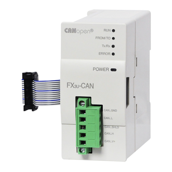
1 Introduction -CAN User's Manual 1.2 External Dimensions and Each Part Name External Dimensions and Each Part Name 1.2.1 External dimensions and each part name Unit : mm (inches) [2] [3] 9 (0.36") 4 (0.16") 87 (3.43") 43 (1.7") (0.32") 4.5 mounting holes Mass (Weight): Approx. -
Page 25: Power And Status Leds
1 Introduction -CAN User's Manual 1.2 External Dimensions and Each Part Name 1.2.2 Power and status LEDs LED Name LED Color Status Description Layer 2 offline mode ® SINGLE FLASH CANopen STOPPED state ® BLINKING CANopen PRE-OPERATIONAL state Green LSS Services in progress FLICKERING ®... -
Page 26: System Configuration
The transmission distance is reduced to 25 m (82') at the maximum baud rate of 1 Maximum transmission Mbps. distance The maximum distance also depends on the specification of other connected nodes. How to obtain EDS file For EDS file, consult with your local Mitsubishi Electric representative. -
Page 27: Applicable Plc
1 Introduction -CAN User's Manual 1.3 System Configuration 1.3.2 Applicable PLC Model name Applicability Series PLC Ver. 1.00 and later (Up to 8 blocks can be extended Series PLC Ver. 1.40 and later (Up to 8 blocks can be extended Series PLC Ver. -
Page 28: Connection With Plc
1 Introduction -CAN User's Manual 1.3 System Configuration 1.3.3 Connection with PLC The FX -CAN connects with a PLC via an extension cable. The FX -CAN is handled as a special extension block of the PLC. The unit number of the FX -CAN is *1*2 automatically assigned No. -
Page 29: System Start-Up Procedure
1 Introduction -CAN User's Manual 1.4 System Start-up Procedure System Start-up Procedure -CAN Refer to Chapter 1 Outline of system: Outline Applicable PLC ® ® CANopen nodes: Applicable CANopen configuration tool Refer to Chapter 2 Specifications: Check of specifications Operation environment Power supply specifications Performance specifications - Maximum bus length (depends on baud rate) -
Page 30: Specifications
2 Specifications -CAN User's Manual Specifications DESIGN PRECAUTIONS • Make sure to have the following safety circuits outside of the PLC to ensure safe system operation even during external power supply problems or PLC failure. Otherwise, malfunctions may cause serious accidents. 1) Most importantly, have the following: an emergency stop circuit, a protection circuit, an interlock circuit for opposite movements (such as normal vs. -
Page 31: General Specifications
2 Specifications -CAN User's Manual 2.1 General Specifications General Specifications Items other than the following table are equivalent to those of the PLC main unit/CPU Module. For further information of general specifications, refer to the manual of the PLC main unit/CPU Module. →... -
Page 32: Installation
3 Installation -CAN User's Manual 3.1 Connection with PLC Installation INSTALLATION PRECAUTIONS • Make sure to cut off all phases of the power supply externally before attempting installation or wiring work. Failure to do so may cause electric shock or damage to the product. INSTALLATION PRECAUTIONS •... -
Page 33: Mounting
3 Installation -CAN User's Manual 3.2 Mounting Mounting The FX -CAN may be installed in a control cabinet with a 35 mm wide DIN46277 DIN rail mounting or M4 screw direct mounting. 3.2.1 DIN rail mounting The product may be mounted on a 35 mm wide DIN46277 (DIN rail). Fit the upper edge (A in the figure to the right) of the DIN rail mounting groove onto the DIN rail. -
Page 34: Direct Mounting
3 Installation -CAN User's Manual 3.2 Mounting 3.2.2 Direct Mounting The product can be installed directly with screws. An interval space of 1 to 2 mm (0.04" to 0.08") between each unit is necessary. For further information of installation, refer to the following respective PLC manual. →... -
Page 35: Wiring
4 Wiring -CAN User's Manual 4.1 Applicable Cable and Connector Wiring WIRING PRECAUTIONS • Make sure to cut off all phases of the power supply externally before attempting installation or wiring work. Failure to do so may cause electric shock or damage to the product. WIRING PRECAUTIONS •... -
Page 36: Applicable Cable
4 Wiring -CAN User's Manual 4.1 Applicable Cable and Connector 4.1.2 Applicable cable Item Applicable Cable Cable Type Twisted pair cable Unshielded/ Shielded Shielded No. of Pairs 2 pair Conformance Standard ISO 11898/1993 Wire Size 0.3 mm to 0.82 mm (AWG22 to 18) Impedance 120 Ω... -
Page 37: Can-Bus Wiring
4 Wiring -CAN User's Manual 4.2 CAN-Bus Wiring CAN-Bus Wiring 4.2.1 Connecting communication cables (1) CAN_GND (1) CAN_GND (1) CAN_GND Terminating Terminating (2) CAN_L (2) CAN_L (2) CAN_L resistor resistor (3) CAN_SHLD (3) CAN_SHLD (3) CAN_SHLD (4) CAN_H (4) CAN_H (4) CAN_H (5) CAN_V+ (5) CAN_V+... -
Page 38: Grounding Of Twisted Pair Cable
4 Wiring -CAN User's Manual 4.3 Grounding 4.2.3 Grounding of twisted pair cable Strip a part of the coating of the shielded twisted pair cable as shown below, and ground at least 35 mm (1.38") of the exposed shield section. Shielded twisted pair cable Shield 4.2.4... -
Page 39: Introduction Of Functions
5 Introduction of Functions -CAN User's Manual 5.1 Functions List Introduction of Functions Functions List The function list is shown below. Functions Description Reference Function Modes Different Function Modes of the module Section 5.2 and Section 6.5 ® Object Dictionary Section 5.3 Link between CANopen network and PLC... -
Page 40: Object Dictionary
5 Introduction of Functions -CAN User's Manual 5.3 Object Dictionary Object Dictionary ® The Object Dictionary is a structure for data organization within the CANopen network. The data within the Object Dictionary is used to set CAN bus parameters, initialize special functions, control data flow, store data in many formats and send emergency messages. -
Page 41: Data Type Definition Area
5 Introduction of Functions -CAN User's Manual 5.5 Data Type Definition Area Data Type Definition Area Static data types are placed in the object dictionary for definition purposes only. Indexes H0002 to H0008 may be mapped in order to define the appropriate space in the RPDO as not being used by the device. An SDO access results in an error. - Page 42 5 Introduction of Functions -CAN User's Manual 5.6 Communication Profile Area Sub- Stored Index Read/ index Object Description / Set Range Data Type Initial Value to Flash (hex) Write (hex) Visible 100A Software Version 4 Byte ASCII String X.XX String 100B Reserved →...
- Page 43 5 Introduction of Functions -CAN User's Manual 5.6 Communication Profile Area Sub- Stored Index Read/ index Object Description / Set Range Data Type Initial Value to Flash (hex) Write (hex) Number of valid object entries Mapped object Mapped object Mapped object →...
- Page 44 5 Introduction of Functions -CAN User's Manual 5.6 Communication Profile Area Sub- Stored Index Read/ index Object Description / Set Range Data Type Initial Value to Flash (hex) Write (hex) Highest sub-index 1F82 01 to 7F Request NMT Node-ID → Refer to Subsection 5.8.9 All nodes Highest sub-index...
- Page 45 5 Introduction of Functions -CAN User's Manual 5.6 Communication Profile Area Table 5.1: Mode 405 RPDO communication Parameter R: Read access, W: Write access, Reserved: Not existing Index or Sub-index Default value of Sub-Index (hex) Index (hex) 1400 200 + Node-Id Reserved 1401 300 + Node-Id...
- Page 46 5 Introduction of Functions -CAN User's Manual 5.6 Communication Profile Area Default value of Sub-Index (hex) Index (hex) 1626 A5812110 A5812210 A5812310 A5812410 1627 A5812510 A5812610 A5812710 A5812810 1628 A5812910 A5812A10 A5812B10 A5812C10 1629 A5812D10 A5812E10 A5812F10 A5813010 162A A5813110 A5813210 A5813310 A5813410...
- Page 47 5 Introduction of Functions -CAN User's Manual 5.6 Communication Profile Area Table 5.3: Mode 405 TPDO communication Parameter R: Read access, W: Write access, Reserved: Not existing Index or Sub-index Default value of Sub-Index (hex) Index (hex) 1800 4000 0180 + Node-Id Reserved 1801 4000 0280 + Node-Id...
- Page 48 5 Introduction of Functions -CAN User's Manual 5.6 Communication Profile Area Default value of Sub-Index (hex) Index (hex) 1A26 A1012110 A1012210 A1012310 A1012410 1A27 A1012510 A1012610 A1012710 A1012810 1A28 A1012910 A1012A10 A1012B10 A1012C10 1A29 A1012D10 A1012E10 A1012F10 A1013010 1A2A A1013110 A1013210 A1013310 A1013410...
- Page 49 5 Introduction of Functions -CAN User's Manual 5.6 Communication Profile Area Table 5.5: Mode 417 RPDO communication Parameter R: Read access, W: Write access, Reserved: Not existing Index or Sub-index Default value of Sub-Index (hex) Index (hex) RW *1)/R 1400 80000000 Reserved 1401...
- Page 50 5 Introduction of Functions -CAN User's Manual 5.6 Communication Profile Area Default value of Sub-Index (hex) Index (hex) RW *1)/R 1433 FF *1) Reserved 1434 FF *1) Reserved 1435 FF *1) Reserved 1436 FF *1) Reserved 1437 FF *1) Reserved 1438 FF *1) Reserved...
- Page 51 5 Introduction of Functions -CAN User's Manual 5.6 Communication Profile Area Default value of Sub-Index (hex) Index (hex) RW *1)/R 1468 FF *1) Reserved 1469 FF *1) Reserved 146A FF *1) Reserved 146B FF *1) Reserved 146C FF *1) Reserved 146D FF *1) Reserved...
- Page 52 5 Introduction of Functions -CAN User's Manual 5.6 Communication Profile Area Default value of Sub-Index (hex) Index (hex) RW *1)/R 149D Reserved 149E Reserved 149F Reserved 14A0 Reserved 14A1 Reserved 14A2 Reserved 14A3 Reserved 14A4 Reserved 14A5 Reserved 14A6 Reserved 14A7 Reserved 14A8...
- Page 53 5 Introduction of Functions -CAN User's Manual 5.6 Communication Profile Area Default value of Sub-Index (hex) Index (hex) RW *1)/R 1512 Reserved 1513 Reserved 1514 Reserved 1515 Reserved 1516 Reserved 1517 Reserved 1518 to 1519 Reserved 151A Reserved 151B Reserved 151C Reserved 151D...
- Page 54 5 Introduction of Functions -CAN User's Manual 5.6 Communication Profile Area Default value of Sub-Index (hex) Index (hex) RW *1)/R 154B Reserved 154C Reserved 154D Reserved 154E Reserved 154F Reserved 1550 Reserved 1551 Reserved 1552 Reserved 1553 Reserved 1554 Reserved 1555 Reserved 1556...
- Page 55 5 Introduction of Functions -CAN User's Manual 5.6 Communication Profile Area Default value of Sub-Index (hex) Index (hex) RW *1)/R 1590 Reserved 1591 Reserved 1592 to 159F Reserved 15A0 Reserved 15A1 Reserved 15A2 to 15AF Reserved 15B0 Reserved 15B1 Reserved 15B2 to 15BF Reserved 15C0...
- Page 56 5 Introduction of Functions -CAN User's Manual 5.6 Communication Profile Area Default value of Sub-Index (hex) Index H05 to H08 (hex) 1711 6C820108 6C800110 Reserved 1712 Reserved 1713 6C010010 6C040008 00050008 6C330020 Reserved 1714 Reserved 1715 6C060020 Reserved 1716 6B830120 Reserved 1717 6B830220...
- Page 57 5 Introduction of Functions -CAN User's Manual 5.6 Communication Profile Area Default value of Sub-Index (hex) Index H05 to H08 (hex) 174A 83010110 83020110 Reserved 174B 83100108 Reserved 174C 83010210 83020210 Reserved 174D 83100208 Reserved 174E 83010310 83020310 Reserved 174F 83100308 Reserved 1750...
- Page 58 5 Introduction of Functions -CAN User's Manual 5.6 Communication Profile Area Default value of Sub-Index (hex) Index H05 to H08 (hex) 1782 to 178F Reserved 1790 6B830320 Reserved 1791 6B830420 Reserved 1792 to 179F Reserved 17A0 73830320 Reserved 17A1 73830420 Reserved 17A2 to 17AF Reserved...
- Page 59 5 Introduction of Functions -CAN User's Manual 5.6 Communication Profile Area Default value of Sub-Index (hex) Index (hex) RW *1)/R 1934 C00001B0 Reserved 1935 to 1937 Reserved 1938 C0000230 Reserved 1939 to 1941 Reserved 1942 C00001C2 Reserved 1943 Reserved 1944 C00001C0 Reserved 1945 to 1947...
- Page 60 5 Introduction of Functions -CAN User's Manual 5.6 Communication Profile Area Default value of Sub-Index (hex) Index (hex) 1B14 6C000020 6C300020 Reserved 1B15 to 1B17 Reserved 1B18 6B000110 6B000210 6C000310 6C000410 Reserved 1B19 to 1B21 Reserved 1B22 74000010 74030008 67FE0008 74300020 Reserved 1B23...
-
Page 61: Can-Id / Cob-Id
5 Introduction of Functions -CAN User's Manual 5.6 Communication Profile Area 5.6.1 CAN-ID / COB-ID Each message type on each device has a unique 11-bit identifier for bus arbitration and identification on the CAN bus. The lowest CAN-ID wins the bus arbitration. CAN-IDs with lower priority (higher CAN-ID) will wait until the bus is free. -
Page 62: Error Register
5 Introduction of Functions -CAN User's Manual 5.6 Communication Profile Area 5.6.2 Error Register ® The object H1001 provides error information. The CANopen device maps internal errors into this object. It is a part of the emergency object. Device Communication Generic Manufacturer profile... -
Page 63: Rpdo / Tpdo
5 Introduction of Functions -CAN User's Manual 5.6 Communication Profile Area 5.6.5 RPDO / TPDO Real-time data transfer is performed by means of Process Data Objects (PDO). PDO transfer is performed with no protocol overhead. PDOs correspond to objects in the object dictionary and provide the interface to the application objects. Data type and mapping of application objects into a PDO is determined by a corresponding default PDO mapping structure within the object dictionary. - Page 64 5 Introduction of Functions -CAN User's Manual 5.6 Communication Profile Area 1. Object H1400 to H144F 1) Sub-index H01: RPDO COB-ID 28 ... 11 10 ... 0 Valid Reserved H0000 11-bit CAN-ID Bit No. Item Description 11-bit CAN-ID of the CAN base frame Bit 0 to 10 11-bit CAN-ID →...
- Page 65 5 Introduction of Functions -CAN User's Manual 5.6 Communication Profile Area 3. Object H1800 to H184F 1) Sub-index H01: TPDO COB-ID 28 ... 11 10 ... 0 Valid H00000 11-bit CAN-ID Bit No. Item Description 11-bit CAN-ID of the CAN base frame Bit 0 to 10 11-bit CAN-ID →...
- Page 66 5 Introduction of Functions -CAN User's Manual 5.6 Communication Profile Area 4. Object H1A00 to H1A4F Sub-index H01 to H08: TPDO mapping parameter The default mapping is to unsigned 16 bit objects. → Refer to Subsection 7.1.1 31 ... 16 15 ...
- Page 67 5 Introduction of Functions -CAN User's Manual 5.6 Communication Profile Area Example 2: Inhibit time > 0, Event time = 0 The BFM data will be copied into the Object dictionary and a PDO will be sent every time when the data are changed and the inhibit time is not running.
- Page 68 5 Introduction of Functions -CAN User's Manual 5.6 Communication Profile Area Example 4: Inhibit time > 0, Event time > 0, Inhibit time < Event time The BFM data will be copied into the Object dictionary. A PDO will be sent every time when the data are changed and the inhibit time is not running.
- Page 69 5 Introduction of Functions -CAN User's Manual 5.6 Communication Profile Area Example 5: Inhibit time > 0, Event time > 0, Inhibit time > Event time The BFM data will be copied into the Object dictionary and a PDO will be sent every time when the data are changed and the inhibit time is not running.
-
Page 70: Mpdo
5 Introduction of Functions -CAN User's Manual 5.6 Communication Profile Area 5.6.6 MPDO ® A Multiplexed PDO, like an SDO, provides direct write access to objects of a CANopen device's object dictionary. The size of the data of these objects is limited to a maximum of 4 bytes. ®... -
Page 71: Sync
5 Introduction of Functions -CAN User's Manual 5.6 Communication Profile Area 5.6.7 SYNC The SYNC producer broadcasts the synchronization object periodically. The SYNC message provides the basic network synchronization mechanism. The time period between SYNC messages is specified by the standard parameter communication cycle period. -
Page 72: Node Guarding
5 Introduction of Functions -CAN User's Manual 5.6 Communication Profile Area 5.6.8 Node guarding This protocol is used to detect remote errors in the network. Each NMT slave serves one requests message for the node guarding protocol. The NMT master polls each NMT guarding slave at regular time intervals. This time-interval is called the guard time and may be different for each NMT slave. -
Page 73: Heartbeat
5 Introduction of Functions -CAN User's Manual 5.6 Communication Profile Area 5.6.9 Heartbeat The heartbeat protocol defines an error control service that does not use requests. A heartbeat producer transmits a heartbeat message cyclically. One or more heartbeat consumers receive the indication. The relationship between producer and consumer is configurable via the object dictionary. -
Page 74: Time
5 Introduction of Functions -CAN User's Manual 5.6 Communication Profile Area 5.6.10 TIME The TIME producer broadcasts the time stamp object. This TIME provides the simple network clock. The time stamp contains the Time of day, which is represented by a 48 bit sequence. These sequences represent the time in milliseconds after midnight (28 bits) and the number of days since 1984-01-01 (16 bits). -
Page 75: Restore Default Parameters
5 Introduction of Functions -CAN User's Manual 5.6 Communication Profile Area 5.6.12 Restore default parameters To restore factory default parameters, write SDO H64616F6C (ISO8859 code: daol ("load")) to Object Index H1011, Sub-Index H01 or use the restore command in the CIF. The stored parameters are then overwritten to factory default settings. - Page 76 5 Introduction of Functions -CAN User's Manual 5.6 Communication Profile Area 1. Object H1014: COB-ID EMCY 28 ... 11 10 ... 0 valid H00000 11-bit CAN-ID → For the resulting COB-ID, refer to Subsection 5.6.1 Bit No. Item Description Bit 0 to 10 11-bit CAN-ID 11-bit CAN-ID of the CAN base frame Bit 11 to 28...
-
Page 77: Error Behaviour
5 Introduction of Functions -CAN User's Manual 5.7 Error Behaviour Error Behaviour ® ® If a serious CANopen device failure is detected in NMT state Operational, the CANopen device ® automatically shifts to the NMT state Pre-operational by default. Alternatively, the CANopen device can be configured to change to NMT state Stopped or remain in the current NMT state. -
Page 78: Network Management
5 Introduction of Functions -CAN User's Manual 5.8 Network Management Network Management ® ® The NMT provides services for controlling the network behaviour of CANopen devices. All CANopen devices of a network referred to as NMT slaves are controlled by services provided by an NMT master. The NMT master is typically also the Application master at the same time, but it is not necessary. -
Page 79: Protocol Boot-Up
5 Introduction of Functions -CAN User's Manual 5.8 Network Management 3. NMT state Stopped ® By switching a CANopen device into the NMT state Stopped, it is forced to stop all communication. Furthermore, this NMT state may be used to achieve certain application behaviour. 4. -
Page 80: Nmt Slave Identification
5 Introduction of Functions -CAN User's Manual 5.8 Network Management 5.8.4 NMT slave identification The NMT startup master and the LSS master are using the NMT slave identification data to identify the NMT slave before configuring the NMT slave. If the configured identification data on the NMT master are different than responded from the NMT slave, the NMT startup master service will stop the startup of this NMT slave. - Page 81 5 Introduction of Functions -CAN User's Manual 5.8 Network Management OD Index Keep NMT Slaves H1F81 Bit 4 in Operational? NMT service Reset Note: If the Flying Master function is NMT service Reset communication for communication used, a Reset Communication each individual CANopen ®...
- Page 82 5 Introduction of Functions -CAN User's Manual 5.8 Network Management Switch to NMT state OPERATIONAL OD Index Start NMT slaves with All optional NMT slaves H1F80 Bit 1, 3 NMT start all nodes? started successfully? NMT service Start NMT service Start remote node with remote for each NMT slave...
- Page 83 5 Introduction of Functions -CAN User's Manual 5.8 Network Management Object H1F80: NMT startup ® This object configures the start up behaviour of a CANopen device via SDO access. If the node is set as Master without the flying master capability, the node starts as NMT master and ignores "all Nodes" NMT commands from the network.
-
Page 84: Nmt Slave Startup
5 Introduction of Functions -CAN User's Manual 5.8 Network Management 5.8.6 NMT slave startup If the NMT Master shall startup the NMT Slave, the NMT startup Master uses the Indexes H1F84 to H1F88 to identify the NMT Slaves during Boot-up. The Setting of these Indexes is optional. The NMT startup Master will request the Index H1000 of the NMT slave to check if the NMT Slave is available in the network. - Page 85 5 Introduction of Functions -CAN User's Manual 5.8 Network Management OD Indexes H1F85 to H1F88 Request OD Index OD Indexes Identity check Response received H1018 from NMT H1F85 to required? and OK? Slave H1F88 Keep alive bit OD Index Check Node state Node state received? for this NMT H1F81 Bit 4...
-
Page 86: Nmt Slave Assignment
5 Introduction of Functions -CAN User's Manual 5.8 Network Management 5.8.7 NMT slave assignment This object configures on the NMT Master for each node-ID (corresponding to the sub-index), the node guarding values and the NMT Slave Configuration. Each sub-index of this object corresponds to the node-ID ®... - Page 87 5 Introduction of Functions -CAN User's Manual 5.8 Network Management Bit No. Item Description ® OFF (0): NMT service Reset communication may be executed for the CANopen device at any time ® ON (1): NMT service Reset communication is not executed for the CANopen device in case the ®...
-
Page 88: Nmt Bootup / Error Event Handling
5 Introduction of Functions -CAN User's Manual 5.8 Network Management 5.8.8 NMT Bootup / Error Event handling When Consumer Heartbeat time elapses, Node Guarding failed or the NMT Slave responds a unexpected Node state, the NMT Master handles the NMT Slave as shown in Figure 5.4. If the NMT Master receives at any time a Boot-Up message from an assigned NMT Slave, the NMT Slave will be startup by the NMT startup Master. -
Page 89: Request Nmt
5 Introduction of Functions -CAN User's Manual 5.8 Network Management 5.8.9 Request NMT ® This object indicates at the NMT Master the current NMT state of a unique CANopen device in the network. ® The sub-index corresponds to the node-ID of the CANopen devices in the network. -
Page 90: Request Node Guarding
5 Introduction of Functions -CAN User's Manual 5.8 Network Management 5.8.10 Request node guarding ® This object indicates the node guarding state for a unique CANopen device in the network. The sub-index ® corresponds to the node-ID of the CANopen devices in the network. - Page 91 5 Introduction of Functions -CAN User's Manual 5.8 Network Management Point When using the Flying Master function, please consider the following points: • The Network communication will be reset after the Active NMT Master fails which will result in an Interruption of the System Application.
- Page 92 5 Introduction of Functions -CAN User's Manual 5.8 Network Management To the previous page Flying master priority = Priority level 128 + Node-Id The lower the number is, the higher the priority! Send Service Confirmation NMT flying master OD Index H1F90 negotiation Sub-index H03 priority >...
-
Page 93: Lss
5 Introduction of Functions -CAN User's Manual 5.8 Network Management 5.8.12 LSS The FX -CAN uses the layer setting services and protocols, to configure via the CAN network the Baud Rate and the Node Address of an LSS slave device that is sealed against harsh environments and that does not have any hardware components like DIP-switches for setting the node-ID or bit timing parameters. - Page 94 5 Introduction of Functions -CAN User's Manual 5.8 Network Management 1. Object H1020: Verify configuration This object indicates the downloaded configuration date and time on the NMT Slave. A configuration manager uses this object to verify the configuration after a reset to check if a reconfiguration is necessary. If on a NMT Slave the Object dictionary configuration is changed, the Sub-indexes H01 and H02 values will be set to H0.
-
Page 95: Device Profile Cia ® 405 V2.0 For Iec 61131-3 Programmable Devices
5 Introduction of Functions -CAN User's Manual ® 5.9 Device Profile CiA 405 V2.0 for IEC 61131-3 Programmable Devices ® Device Profile CiA 405 V2.0 for IEC 61131-3 Programmable Devices This section describes the Device Profile for IEC 61131-3 programmable devices. The objects for data read/ write support signed 8bit, unsigned 8bit, signed 16bit, unsigned 16bit, signed 32bit, unsigned 32bit and float 32bit. - Page 96 5 Introduction of Functions -CAN User's Manual ® 5.9 Device Profile CiA 405 V2.0 for IEC 61131-3 Programmable Devices Index Sub-index Data Initial Read/ Object Description (hex) (hex) type value Write Highest sub-index A200 Input network variables 01 to A0 Unsigned Integer 32 bit Highest sub-index A240...
-
Page 97: Application Profile Cia ® 417 V2.1 For Lift Control Systems
5 Introduction of Functions -CAN User's Manual ® 5.10 Application Profile CiA 417 V2.1 for Lift Control Systems ® 5.10 Application Profile CiA 417 V2.1 for Lift Control Systems This application profile describes the virtual devices (hereinafter called VD) of lift control systems. The virtual controllers (e.g. - Page 98 5 Introduction of Functions -CAN User's Manual ® 5.10 Application Profile CiA 417 V2.1 for Lift Control Systems ® The table below provides a brief description and reference information for the FX -CAN CANopen Object Dictionary. Note: Stored to Flash ROM Data will be saved to the Flash ROM by using the Store Parameter command in Index H1010.
- Page 99 5 Introduction of Functions -CAN User's Manual ® 5.10 Application Profile CiA 417 V2.1 for Lift Control Systems Sub- Stored Index Data Read/ index Object Description Initial value to Flash (hex) type Write (hex) Highest sub-index 1: 6383 2: 6B83 Position unit 1 HFFFF FFFF 3: 7383...
-
Page 100: Lift Number
5 Introduction of Functions -CAN User's Manual ® 5.10 Application Profile CiA 417 V2.1 for Lift Control Systems Sub- Stored Index Data Read/ index Object Description Initial value to Flash (hex) type Write (hex) 1: 6407 This object is equivalent to object H6064 in the 2: 6C07 ®... -
Page 101: Virtual Input Mapping
5 Introduction of Functions -CAN User's Manual ® 5.10 Application Profile CiA 417 V2.1 for Lift Control Systems 5.10.2 Virtual input mapping This Object contains the last received input data from one of the digital input panel group objects. 47 ... 40 39 ... - Page 102 5 Introduction of Functions -CAN User's Manual ® 5.10 Application Profile CiA 417 V2.1 for Lift Control Systems 3. Lift field The Bit for the requested lift number is set to ON (1). Lift 8 Lift 7 Lift 6 Lift 5 Lift 4 Lift 3 Lift 2...
-
Page 103: Virtual Output Mapping
5 Introduction of Functions -CAN User's Manual ® 5.10 Application Profile CiA 417 V2.1 for Lift Control Systems 5.10.3 Virtual output mapping This Object contains the output data for one of the digital output group objects. 47 ... 40 39 ... 32 31 ... - Page 104 5 Introduction of Functions -CAN User's Manual ® 5.10 Application Profile CiA 417 V2.1 for Lift Control Systems Basic function field Sub-function field Bit 0 to 7 value Bit 8 to 15 value Description (hex) (hex) Request key lock 4 acknowledgement Request door open acknowledgement Request door close acknowledgement Fire recall (key switch hall panel) acknowledgement...
- Page 105 5 Introduction of Functions -CAN User's Manual ® 5.10 Application Profile CiA 417 V2.1 for Lift Control Systems Basic function field Sub-function field Bit 0 to 7 value Bit 8 to 15 value Description (hex) (hex) Fire brigade service Help is coming Special service Load time Occupied...
-
Page 106: Door Control Word
5 Introduction of Functions -CAN User's Manual ® 5.10 Application Profile CiA 417 V2.1 for Lift Control Systems 6. Function data field The function data provides the input state of a virtual input. 46 ... 44 43 ... 41 Predicate Property parameter Property Status... -
Page 107: Door Status Word
5 Introduction of Functions -CAN User's Manual ® 5.10 Application Profile CiA 417 V2.1 for Lift Control Systems 3. Finger protector field Bit 6 to 7 Value (hex) Description Enable finger protector Disable finger protector Reserved Do not care / take no action 4. - Page 108 5 Introduction of Functions -CAN User's Manual ® 5.10 Application Profile CiA 417 V2.1 for Lift Control Systems 2. Battery power field Bit 2 to 3 Value (hex) Description No battery power used Battery power used Error indicator Not available or not installed 3.
-
Page 109: Light Barrier Status
5 Introduction of Functions -CAN User's Manual ® 5.10 Application Profile CiA 417 V2.1 for Lift Control Systems 5.10.6 Light barrier status This Object contains the status information of the VD light barrier unit for up to four doors. 7 ... 6 5 ... - Page 110 5 Introduction of Functions -CAN User's Manual ® 5.10 Application Profile CiA 417 V2.1 for Lift Control Systems Status transition Number: Transition No. Power Fault disabled Start Fault reaction active Not ready to switch on Fault Switch on disabled Ready to switch on Power enabled...
-
Page 111: Status Word
5 Introduction of Functions -CAN User's Manual ® 5.10 Application Profile CiA 417 V2.1 for Lift Control Systems 5.10.8 Status word ® This object is equivalent to object H6041 in the CiA 402-2 V3.0 specification. 15 ... 14 13 ... 12 rtso Bit No. -
Page 112: Modes Of Operation
5 Introduction of Functions -CAN User's Manual ® 5.10 Application Profile CiA 417 V2.1 for Lift Control Systems 5.10.9 Modes of operation ® This object is equivalent to object H6060 in the CiA 402-2 V3.0 specifications. Value Description -128 to -1 Manufacturer-specific operation modes No mode change or no mode assigned Profile position mode... -
Page 113: Allocation Of Buffer Memories
6 Allocation of Buffer Memories -CAN User's Manual 6.1 Buffer Memories (BFM) Lists Allocation of Buffer Memories Buffer Memories (BFM) Lists Caution • Do not access buffer memory (BFM) that is marked as "Reserved" (Ex. BFM #23, #28, #31 to #34, #40 to #49, #60 to #99, #400, #443 to #600, etc.) by FROM/TO instructions, etc. - Page 114 6 Allocation of Buffer Memories -CAN User's Manual 6.1 Buffer Memories (BFM) Lists Default Read/ Stored to BFM No. Description Reference value Write Flash ROM Time stamp producer/consumer BFM #50 ® (CANopen modes only) Time stamp year BFM #51 ® (CANopen modes only) Time stamp month...
- Page 115 6 Allocation of Buffer Memories -CAN User's Manual 6.1 Buffer Memories (BFM) Lists Default Read/ Stored to BFM No. Description Reference value Write Flash ROM BFM #3540 to #9999 Reserved Receive Process Data (RPDO) Section 7.1 BFM #10000 to #10319 ®...
-
Page 116: How To Read/Write From/To Buffer Memory
6 Allocation of Buffer Memories -CAN User's Manual 6.2 How to Read/Write from/to Buffer Memory How to Read/Write from/to Buffer Memory To read/write from/to buffer memory in the FX -CAN, use the FROM/TO instructions or the applied instructions that directly specify the buffer memory. /FX5U/FX5UC PLC applicable software is required to perform direct specification of the buffer memory and bit specification of word devices. -
Page 117: Receive/Transmit Process Data
6 Allocation of Buffer Memories -CAN User's Manual 6.3 Receive/Transmit Process Data Receive/Transmit Process Data BFM #10000 to #10319 and #11000 to #11319 locations in the FX -CAN module are used for data communication to the CAN bus. The mapping for where each data is sent/received is explained in the following chapter. -
Page 118: Bfm #21] Function Mode
6 Allocation of Buffer Memories -CAN User's Manual 6.5 [BFM #21] Function Mode Description FROM (Read Access) TO (Write Access) Only in 417 Function mode (Refer to BFM #21): Data exchange for the Virtual Input mapping BFMs. With this bit it's possible to read the Receive Buffer of the Virtual Input mapping without exchanging the data of all data exchange BFMs. -
Page 119: Bfm #22] Save/Restore Configuration
6 Allocation of Buffer Memories -CAN User's Manual 6.6 [BFM #22] Save/Restore Configuration [BFM #22] Save/Restore Configuration This BFM supports two bits that allow the default configuration of the BFMs to be restored and the configuration from BFMs to be stored into Flash ROM. Both bits will be reset automatically if the restore or save procedure is completed. -
Page 120: Bfm #24] Baud Rate
6 Allocation of Buffer Memories -CAN User's Manual 6.7 [BFM #24] Baud Rate [BFM #24] Baud Rate Set the baud rate in this BFM. The current baud rate can be found in BFM #37. Note • The Baud Rate must be equal for all nodes in the network. •... - Page 121 6 Allocation of Buffer Memories -CAN User's Manual 6.8 [BFM #25] Communication Status Description FROM (Read Access) TO (Write Access) ® CANopen mode: Reserved Layer 2 mode: OFF: Layer 2 request configuration mode Bit 4 Layer 2 request online mode This bit must be set to ON to start data exchange with other network nodes.
-
Page 122: Bfm #26] From/To Watchdog
6 Allocation of Buffer Memories -CAN User's Manual 6.9 [BFM #26] FROM/TO Watchdog [BFM #26] FROM/TO Watchdog The FROM/TO Watchdog can be used when the Module is online to monitor if the PLC program accesses data BFM #0 to BFM #19, BFM #100 to #399 or BFM #3000 to BFM #3539 cyclically. After the first FROM/TO on the data BFM, the Watchdog will check if the next access to the data BFM takes place before the time set in BFM #26 expires. -
Page 123: Bfm #35] Can Transmission Error Counter
6 Allocation of Buffer Memories -CAN User's Manual 6.13 [BFM #35] CAN Transmission Error Counter 6.13 [BFM #35] CAN Transmission Error Counter -CAN stores the current value of the CAN transmit error counter. The CAN transmit message error counter counts up to K256. The counter counts 1 or 8 up if a transmission error is detected. -
Page 124: Bfm #50 To #59] Time Stamp
6 Allocation of Buffer Memories -CAN User's Manual 6.19 [BFM #50 to #59] Time Stamp 6.19 [BFM #50 to #59] Time Stamp ® CANopen devices which operate a local clock may use the TIME object to adjust their own time base to the time of the time stamp producer. -
Page 125: Bfm #70] Nmt Start All Nodes Delay
6 Allocation of Buffer Memories -CAN User's Manual 6.20 [BFM #70] NMT Start all Nodes delay BFM No. Name Description K0 to K99 (lower two digits) K0 to K99 in Time stamp year corresponds to 2000 to 2099 year. BFM #51 Time stamp year The higher two digits is ignored. -
Page 126: Bfm #601 To #727] Nmt State
6 Allocation of Buffer Memories -CAN User's Manual 6.22 [BFM #601 to #727] NMT State 6.22 [BFM #601 to #727] NMT State ® This BFM displays the NMT status of the CANopen nodes (index H1F82, Sub index 01 to 127 of the ®... -
Page 127: Bfm #750 To #859] Emergency Message Buffer
6 Allocation of Buffer Memories -CAN User's Manual 6.23 [BFM #750 to #859] Emergency Message Buffer 6.23 [BFM #750 to #859] Emergency Message Buffer The FX -CAN will store the Emergency messages which are received from the bus to an internal buffer. This buffer can store up to 22 emergency messages and is separated into an 11 message stack buffer (BFM #750 to #804) and an 11 message ring buffer (BFM #805 to #859). - Page 128 6 Allocation of Buffer Memories -CAN User's Manual 6.23 [BFM #750 to #859] Emergency Message Buffer Emergency error codes ® In different CiA Device/Application Profiles, more EMCY Error Codes are defined. → For EMCY Error Codes that are not in the following table, refer to the manual of the device which sent the message Error Error...
-
Page 129: Bfm #900 To #963] Nmt Error Control Status
6 Allocation of Buffer Memories -CAN User's Manual 6.24 [BFM #900 to #963] NMT Error Control Status 6.24 [BFM #900 to #963] NMT Error Control Status This BFM displays the Node Guarding and Heartbeat status. Note • When resetting the local NMT error latch, write H0 to the corresponding bit of this BFM. •... -
Page 130: Canopen 405 Mode
® 7 CANopen 405 Mode -CAN User's Manual ® 7.1 Data Transfer Location for CANopen 405 Mode ® CANopen 405 Mode ® Data Transfer Location for CANopen 405 Mode ® This section explains data transfer locations for CANopen 405 mode. BFM #10000 to #10319 and #11000 to #11319 are used as data transfer locations. - Page 131 ® 7 CANopen 405 Mode -CAN User's Manual ® 7.1 Data Transfer Location for CANopen 405 Mode Index Index Index Index Index Index Index HA240 HA200 HA1C0 HA100 HA0C0 HA040 HA000 float unsigned signed unsigned signed unsigned signed 32 bit 32 bit 32 bit 16 bit...
-
Page 132: Direct From Bfm Access To The Canopen ® 405 Object
® 7 CANopen 405 Mode -CAN User's Manual ® 7.1 Data Transfer Location for CANopen 405 Mode ® 7.1.2 Direct FROM BFM access to the CANopen 405 Object Use the FROM instruction to read data from the following locations. The default RPDO mapping is assigned to unsigned 16 bit objects (Index HA580). - Page 133 ® 7 CANopen 405 Mode -CAN User's Manual ® 7.1 Data Transfer Location for CANopen 405 Mode Index Index Index Index Index Index Index HA6C0 HA680 HA640 HA581 HA541 HA4C1 HA481 float unsigned signed unsigned signed unsigned signed 32 bit 32 bit 32 bit 16 bit...
-
Page 134: Pdo Mapping/Binding Of The Network For Canopen ® 405 Mode
® 7 CANopen 405 Mode -CAN User's Manual ® 7.2 PDO Mapping/Binding of the Network for CANopen 405 Mode ® PDO Mapping/Binding of the Network for CANopen 405 Mode ® In order to exchange data by CANopen , the data channels between the nodes must be defined or "mapped". ®... -
Page 135: Tpdo Mapping Table
® 7 CANopen 405 Mode -CAN User's Manual ® 7.2 PDO Mapping/Binding of the Network for CANopen 405 Mode 7.2.1 TPDO mapping table The assignment in this table is only for the default TPDO mapping setting (unsigned 16 bit objects). To change the BFM assignment of the TPDO, the mapping parameter has to be changed in the Object Dictionary. - Page 136 ® 7 CANopen 405 Mode -CAN User's Manual ® 7.2 PDO Mapping/Binding of the Network for CANopen 405 Mode Mode 0 Mapping Mode A Mapping Mode B Mapping (default) TPDO Assigned BFM COB ID #180 to #183 TPDO 26 #11100 to #11103 #184 to #187 TPDO 27 #11104 to #11107...
- Page 137 ® 7 CANopen 405 Mode -CAN User's Manual ® 7.2 PDO Mapping/Binding of the Network for CANopen 405 Mode Mode 0 Mapping Mode A Mapping Mode B Mapping (default) TPDO Assigned BFM COB ID #300 to #303 TPDO 56 #11220 to #11223 #304 to #307 TPDO 57 #11224 to #11227...
-
Page 138: Rpdo Mapping Table
® 7 CANopen 405 Mode -CAN User's Manual ® 7.2 PDO Mapping/Binding of the Network for CANopen 405 Mode 7.2.2 RPDO mapping table The assignment in this table is only for the default RPDO mapping setting (unsigned 16 bit objects). To change the BFM assignment of the RPDO, the mapping parameter has to be changed in the Object Dictionary. - Page 139 ® 7 CANopen 405 Mode -CAN User's Manual ® 7.2 PDO Mapping/Binding of the Network for CANopen 405 Mode Mode 0 Mapping Mode A Mapping Mode B Mapping (default) RPDO Assigned BFM COB ID #176 to #179 RPDO 25 H0187 #10096 to #10099 #180 to #183 RPDO 26...
- Page 140 ® 7 CANopen 405 Mode -CAN User's Manual ® 7.2 PDO Mapping/Binding of the Network for CANopen 405 Mode Mode 0 Mapping Mode A Mapping Mode B Mapping (default) RPDO Assigned BFM COB ID #296 to #299 RPDO 55 #10216 to #10219 #300 to #303 RPDO 56 #10220 to #10223...
-
Page 141: Mode 0 Mapping
® 7 CANopen 405 Mode -CAN User's Manual ® 7.2 PDO Mapping/Binding of the Network for CANopen 405 Mode 7.2.3 Mode 0 mapping By executing the Mode 0 mapping command shown below, the number of automatically assigned TPDOs and RPDOs becomes four. All RPDO/TPDO communication and mapping parameter and the BFM/Object dictionary assignment will be reset to factory default. -
Page 142: Mode B Cob-Id Mapping
® 7 CANopen 405 Mode -CAN User's Manual ® 7.2 PDO Mapping/Binding of the Network for CANopen 405 Mode Execution procedure: Mode A mapping 1) To execute the Mode A command, write H8200 to BFM #1000. 2) After the Mapping is successfully established, H8201 is written to BFM #1000. →... - Page 143 ® 7 CANopen 405 Mode -CAN User's Manual ® 7.2 PDO Mapping/Binding of the Network for CANopen 405 Mode Assign Source TPDO COB-ID to Destination RPDO COB-ID This command copies the COB-ID of the Source Node TPDO to the Destination Node RPDO. Please ensure that the PDO mapping parameter data fit together before executing this command.
- Page 144 ® 7 CANopen 405 Mode -CAN User's Manual ® 7.2 PDO Mapping/Binding of the Network for CANopen 405 Mode 2. Destination Parameter The Destination parameter defines the destination for the corresponding source parameter data. It consists of two bytes, with the node ID in the high byte and the PDO number in the low byte. •...
- Page 145 ® 7 CANopen 405 Mode -CAN User's Manual ® 7.2 PDO Mapping/Binding of the Network for CANopen 405 Mode Description BFM No. TO (Write Access) FROM (Read Access) High Byte Low Byte H8301: Mapping successfully established H83FF: Parameter Error BFM #1000 Command: H8300 HFFFF:...
-
Page 146: Mode B Cob-Id Mapping Errors
® 7 CANopen 405 Mode -CAN User's Manual ® 7.2 PDO Mapping/Binding of the Network for CANopen 405 Mode 7.2.6 Mode B COB-ID Mapping Errors This subsection describes the parameter error H83FF occurring in mode B COB-ID Mapping. If the CIF was not able to execute the "mode B COB-ID Mapping" command with the given parameter set, it will return H83FF in BFM #1000. -
Page 147: Canopen 417 Mode
® 8 CANopen 417 Mode -CAN User's Manual 8.1 Buffer Memories Lists of Lift Application ® CANopen 417 Mode ® This chapter describes the data transfer locations of the CANopen 417 Mode. ® For further information on application Profile CiA 417 V2.1 for lift control systems, refer to the following section. - Page 148 ® 8 CANopen 417 Mode -CAN User's Manual 8.1 Buffer Memories Lists of Lift Application - Transmission Objects BFM No. and access type Lift No. Description Initial value Reference FROM/TO BFM #3001 BFM #13001 BFM #3002 BFM #13002 1 to 8 Virtual output mapping Section 8.3 BFM #3003...
- Page 149 ® 8 CANopen 417 Mode -CAN User's Manual 8.1 Buffer Memories Lists of Lift Application BFM No. and access type Lift No. Description Initial value Reference FROM FROM BFM #3086 BFM #12086 Door 1 BFM #3087 BFM #12087 Door 2 Door position HFFFF BFM #3088...
- Page 150 ® 8 CANopen 417 Mode -CAN User's Manual 8.1 Buffer Memories Lists of Lift Application BFM No. and access type Lift No. Description Initial value Reference FROM FROM BFM #3138 BFM #12138 Door 1 BFM #3139 BFM #12139 Door 2 Light barrier status BFM #3140 BFM #12140...
- Page 151 ® 8 CANopen 417 Mode -CAN User's Manual 8.1 Buffer Memories Lists of Lift Application • Car drive controller The car drive controller transmits commands to the car drive unit. It receives status information from the car drive unit and the loadmeasuring unit. If the profile position mode is used, the car drive controller needs additional status information from the car position unit.
- Page 152 ® 8 CANopen 417 Mode -CAN User's Manual 8.1 Buffer Memories Lists of Lift Application BFM No. and access type Lift No. Description Initial value Reference FROM FROM BFM #3348 BFM #12348 Position unit 1 BFM #3349 BFM #12349 BFM #3350 BFM #12350 Position unit 2 BFM #3351...
- Page 153 ® 8 CANopen 417 Mode -CAN User's Manual 8.1 Buffer Memories Lists of Lift Application BFM No. and access type Lift No. Description Initial value Reference FROM FROM BFM #3396 BFM #12396 Position unit 1 BFM #3397 BFM #12397 Position unit 2 Acceleration value car BFM #3398 BFM #12398...
- Page 154 ® 8 CANopen 417 Mode -CAN User's Manual 8.1 Buffer Memories Lists of Lift Application BFM No. and access type Lift No. Description Initial value Reference FROM FROM BFM #3444 BFM #12444 BFM #3445 BFM #12445 BFM #3446 BFM #12446 BFM #3447 BFM #12447 BFM #3448...
- Page 155 ® 8 CANopen 417 Mode -CAN User's Manual 8.1 Buffer Memories Lists of Lift Application BFM No. and access type Lift No. Description Initial value Reference FROM FROM BFM #3508 BFM #12508 Absolute load value HFFFF Load value BFM #3509 BFM #12509 SI unit BFM #3510...
- Page 156 ® 8 CANopen 417 Mode -CAN User's Manual 8.1 Buffer Memories Lists of Lift Application BFM No. and access type Lift No. Description Initial value Reference FROM/TO BFM #3436 BFM #13436 BFM #3437 BFM #13437 BFM #3438 BFM #13438 BFM #3439 BFM #13439 Modes of operation Section 8.11...
- Page 157 ® 8 CANopen 417 Mode -CAN User's Manual 8.1 Buffer Memories Lists of Lift Application BFM No. and access type Lift No. Description Initial value Reference FROM/TO BFM #3492 BFM #13492 BFM #3493 BFM #13493 BFM #3494 BFM #13494 BFM #3495 BFM #13495 BFM #3496 BFM #13496...
-
Page 158: Lift Number
® 8 CANopen 417 Mode -CAN User's Manual 8.2 Lift Number Lift Number This BFM contains the lift number to which the FX -CAN is assigned. The Bit for the assigned lift number is set to ON (1). Note Only the application BFMs for which the Lift corresponding bit is set will be updated. Data save to Flash ROM Data can be saved in Flash ROM by CIF. - Page 159 ® 8 CANopen 417 Mode -CAN User's Manual 8.3 Virtual Input/Output Mapping 2. Sub-function field [High byte in BFM #3001 and #12001] The Sub-function field interprets depending on the basic function field value. Basic Sub-Function Basic Sub-Function Function Field Field Function Field Field BFM #3001...
- Page 160 ® 8 CANopen 417 Mode -CAN User's Manual 8.3 Virtual Input/Output Mapping 4. Floor field [High byte in BFM #3002 and #12002] BFM #3002 BFM #12002 Description High Byte Value (hex) Car panel 01 to FE Panel of floor 1 to 254 Reserved 5.
-
Page 161: Virtual Output Mapping
® 8 CANopen 417 Mode -CAN User's Manual 8.3 Virtual Input/Output Mapping 8.3.2 Virtual output mapping These BFMs contain the output data for one of the digital output group objects. Description BFM #3003 BFM #3002 BFM #3001 BFM No. BFM #13003 BFM #13002 BFM #13001 High Byte... - Page 162 ® 8 CANopen 417 Mode -CAN User's Manual 8.3 Virtual Input/Output Mapping Basic Function Sub-Function Field Field BFM #3001 BFM #3001 Description BFM #13001 BFM #13001 Low Byte Value High Byte Value (hex) (hex) Reserved Request fan 1 acknowledgement Request fan 2 acknowledgement Request load time 1 acknowledgement Request load time 2 acknowledgement Request key lock 1 acknowledgement...
- Page 163 ® 8 CANopen 417 Mode -CAN User's Manual 8.3 Virtual Input/Output Mapping Basic Function Sub-Function Field Field BFM #3001 BFM #3001 Description BFM #13001 BFM #13001 Low Byte Value High Byte Value (hex) (hex) This sub-function shows the arrow display direction up/down, and the transfer direction display of the car. 15 ...
- Page 164 ® 8 CANopen 417 Mode -CAN User's Manual 8.3 Virtual Input/Output Mapping 4. Floor field [High byte in BFM #3002 and #13002] BFM #3002 BFM #13002 Description High Byte Value (hex) Car panel 01 to FE Floor number 1 to 254 All floor panels 5.
-
Page 165: Door Control Word/Door Status Word
® 8 CANopen 417 Mode -CAN User's Manual 8.4 Door Control Word/Door Status Word Door Control Word/Door Status Word When BFM #3050 to #3081 and #12050 to 12081 are read, the Door status word is read from BFMs. When BFM #13050 to #13081 are read, the Door control word is read from BFMs. And when BFM #3050 to #3081 and #13050 to #13081 are written to, the Door control word is written to BFMs. -
Page 166: Door Status Word
® 8 CANopen 417 Mode -CAN User's Manual 8.4 Door Control Word/Door Status Word 6. Command field [Bit 12 to 15] Bit 12 to 15 Value (hex) Description Close door without limit force (Not allowed for EN-81 compliant lifts) Close door with limit force Nudging (Forced closing of car door with reduced speed without reversal devices due to the blocked door for too long time) -
Page 167: Door Position
® 8 CANopen 417 Mode -CAN User's Manual 8.5 Door Position 5. Motion detector field [Bit 8, 9] Bit 9 Bit 8 Description OFF(0) OFF(0) Motion not detected OFF(0) ON (1) Motion detected ON (1) OFF(0) Error indicator ON (1) ON (1) Not available or not installed 6. -
Page 168: Speed Value Car
® 8 CANopen 417 Mode -CAN User's Manual 8.8 Speed Value Car Speed Value Car These BFMs store the Speed value from the car position units of each Lift number. The measuring step is defined in object H6384 of the car position unit. Acceleration Value Car These BFMs store the acceleration value from the car position units of each Lift number. - Page 169 ® 8 CANopen 417 Mode -CAN User's Manual 8.10 Control Word/Status Word Status transition Number: Transition No. Power Fault disabled Start Fault reaction active Not ready to switch on Fault Switch on disabled Ready to switch on Power enabled Switched on Operation Quick stop enabled...
-
Page 170: Status Word
® 8 CANopen 417 Mode -CAN User's Manual 8.10 Control Word/Status Word 8.10.2 Status word ® This Car drive Status word is equivalent to object H6041 in the CiA 402-2 V3.0 specification. 15 ... 14 13 ... 12 rtso Bit No. Item Description / set range Bit 0... -
Page 171: Modes Of Operation/Modes Of Operation Display
® 8 CANopen 417 Mode -CAN User's Manual 8.11 Modes of operation/Modes of operation display 8.11 Modes of operation/Modes of operation display When BFM #3436 to #3443 and #12436 to 12443 are read, the Modes of operation display is read from BFMs. -
Page 172: Target Position
® 8 CANopen 417 Mode -CAN User's Manual 8.14 Profile Velocity 8.13.2 Target position ® This Car drive target position is equivalent to object H607A in the CiA 402-2 V3.0 specifications. This Target position contains the commanded position that the drive should move to in position profile mode using the current settings of the motion control parameters such as velocity, acceleration, deceleration, motion profile type etc. -
Page 173: Can Layer 2 Mode
9 CAN Layer 2 Mode -CAN User's Manual 9.1 Receive/Transmit Process Data CAN Layer 2 Mode This chapter describes the data transfer locations and setting, etc. of the 11 bit/29 bit CAN-ID Layer 2 mode. In the 11 bit/29 bit CAN-ID Layer 2 mode, the FX -CAN can send/receive up to 42 pre-defined messages. - Page 174 9 CAN Layer 2 Mode -CAN User's Manual 9.1 Receive/Transmit Process Data Description Initial Read/ Stored to BFM No. Name value Write Flash ROM High Byte Low Byte BFM #387 CAN-ID 42 LW 11/29 bit CAN-Identifier low word HFFFF BFM #388 CAN-ID 42 HW 29 bit CAN-Identifier high word HFFFF...
- Page 175 9 CAN Layer 2 Mode -CAN User's Manual 9.1 Receive/Transmit Process Data 2. When receiving messages The CAN-ID, RTR/new/DLC and data bytes of each message are as follows. Note In case more than one ID can pass the filter set in BFM #1100 to #1267, the received CAN-ID might change and will always display the CAN-ID, DLC and data of the latest received message.
-
Page 176: Layer 2 Message Specific Error Code List
9 CAN Layer 2 Mode -CAN User's Manual 9.2 Layer 2 Message Specific Error Code List Layer 2 Message Specific Error Code List This List contains an error message for each Layer 2 message. BFM No. Detailed Error Code for Each Layer 2 Message BFM #401 Message 1 error code BFM #402... -
Page 177: Pre-Defined Layer 2 Transmit Messages
9 CAN Layer 2 Mode -CAN User's Manual 9.3 Pre-defined Layer 2 Message Configuration 9.3.1 Pre-defined Layer 2 transmit messages This subsection describes parameters A to D for the transmit message. Parameter Description Initial value Layer 2 message number parameter A Constant HFFFF HFFFF H7FFF (auto RTR response) - Page 178 9 CAN Layer 2 Mode -CAN User's Manual 9.3 Pre-defined Layer 2 Message Configuration 2. Parameter C "transmission type" for each Layer 2 message The transmission type defines the transmit/receive message and transmission trigger event of the message as follows. Transmission Message Type Transmission Trigger Event...
-
Page 179: Pre-Defined Layer 2 Receive Messages
9 CAN Layer 2 Mode -CAN User's Manual 9.3 Pre-defined Layer 2 Message Configuration 9.3.2 Pre-defined Layer 2 receive messages This subsection describes parameters A to D for the receive message. Parameter Description Initial Value Layer 2 message number parameter A Reception CAN-ID low word HFFFF Layer 2 message number parameter B Reception CAN-ID high word HFFFF... - Page 180 9 CAN Layer 2 Mode -CAN User's Manual 9.3 Pre-defined Layer 2 Message Configuration Example 2: Layer 2 message 2 parameter A/B = H00000180 Layer 2 message 2 parameter C/D = H00000006 BFM #107 to #113 stores received messages with CAN-IDs H180, H182, H184 and H186 because ID bits 1 and 2 are not evaluated.
-
Page 181: Layer 2 Rtr Flags
9 CAN Layer 2 Mode -CAN User's Manual 9.4 Layer 2 RTR Flags Layer 2 RTR Flags If the FX -CAN is set to Layer 2 communication mode, an incoming RTR message is indicated in the BFM if the following conditions are satisfied: •... -
Page 182: Message Transmit Trigger Flags
9 CAN Layer 2 Mode -CAN User's Manual 9.5 Message Transmit Trigger Flags Message Transmit Trigger Flags The transmission of a message in Layer 2 mode can be triggered via the following flags. Transmit requests on receive Layer 2 messages are discarded. When a bit is set to ON, the corresponding transmit message will be sent as soon as a transmit buffer is available. - Page 183 9 CAN Layer 2 Mode -CAN User's Manual 9.6 PLC RUN>STOP Messages Description BFM No. Function Layer 2 Message Initial Value High Byte Low Byte BFM #1921 CAN-ID 4 LW 11/29 bit CAN-Identifier low word HFFFF BFM #1922 CAN-ID 4 HW 29 bit CAN-Identifier high word HFFFF BFM #1923...
-
Page 184: Cif Sending Layer 2 Message
9 CAN Layer 2 Mode -CAN User's Manual 9.7 CIF Sending Layer 2 Message CIF Sending Layer 2 Message Using this function, the FX -CAN can send any Layer 2 messages to the CAN bus. This function is accessible only in Layer 2 Mode. Execution procedure: Set Node guarding/NMT Slave Assignment 1) Write the CAN-ID, RTR, DLC and the data byte to BFM #1001 to #1008. -
Page 185: Command Interface
10 Command Interface -CAN User's Manual 10.1 [BFM #1000 to #1066] Command Interface 10. Command Interface This chapter describes the Command Interface supported by FX -CAN. Command Interface that can be used with each Function Mode is shown in the following table. Function Mode Selection Command Interface Reference... -
Page 186: Sdo Request
10 Command Interface -CAN User's Manual 10.2 SDO Request 10.2 SDO Request Note that the NMT Master startup process uses SDO's which can be result in an Error of the CIF command if the NMT Startup Master accesses the remote Node at the same time. 10.2.1 CIF SDO read access Description of CIF SDO read access is shown below. -
Page 187: Cif Multi Sdo Read Access
10 Command Interface -CAN User's Manual 10.2 SDO Request 10.2.2 CIF Multi SDO read access With the multi SDO read access command, up to 8 SDO read accesses can be made within one command. The maximum data length for each access is 8 bytes. At first write the node number (0, 1-127), the Object Dictionary Index and the Sub index to the BFMs. -
Page 188: Cif Sdo Write Access
10 Command Interface -CAN User's Manual 10.2 SDO Request 10.2.3 CIF SDO write access Description of CIF SDO write access is shown below. The local FX -CAN can be specified by its actual node number or by using "0". Execution procedure: CIF SDO write access 1) Write the Node number and the Index / Sub-index of the target Object Dictionary to BFM #1001 to #1003. -
Page 189: Cif Multi Sdo Write Access
10 Command Interface -CAN User's Manual 10.2 SDO Request 10.2.4 CIF Multi SDO write access With the multi SDO write access command, up to 8 SDO write accesses can be made within one command. The maximum data length for each access is 8 bytes. At first write the node number (0, 1-127), the Object Dictionary Index, the Sub-index, the data length (in byte) and the data to be sent to the BFMs. -
Page 190: Set Heartbeat
10 Command Interface -CAN User's Manual 10.3 Set Heartbeat 10.3 Set Heartbeat Nodes can be easily set to Heartbeat Producer or Heartbeat Consumer status by writing values to Index H1016 and H1017 using the Command Interface (CIF). The parameters for Heartbeat are included in the information that can be written to the CAN bus. -
Page 191: Set Node Guarding / Nmt Slave Assignment
10 Command Interface -CAN User's Manual 10.4 Set Node Guarding / NMT Slave Assignment → If H740F, H000F or HFFFF is read from BFM #1000, refer to Section 10.9 Description BFM No. FROM (Read Access) TO (Write Access) H7401: Consuming has been assigned H740F: Parameter Error BFM #1000... -
Page 192: Send An Emergency Message
10 Command Interface -CAN User's Manual 10.5 Send an Emergency Message Description BFM No. FROM (Read Access) TO (Write Access) H8401: Slaves have been assigned H84FF: Parameter Error BFM #1000 Command: H8400 HFFFF: CIF Busy H000F: Error BFM #1001 Slave Number to be Guarded BFM #1002 Slave Configuration 1st target... - Page 193 10 Command Interface -CAN User's Manual 10.5 Send an Emergency Message Emergency error codes ® In different CiA Device/Application Profiles, more EMCY Error Codes are defined. Error Error Code Description Code Description (hex) (hex) 0000 Error reset or no error 7000 Additional modules –...
-
Page 194: Store Object Dictionary Settings
10 Command Interface -CAN User's Manual 10.6 Store Object Dictionary Settings 10.6 Store Object Dictionary Settings This command is an easy to use command for the store parameter command in the Object Dictionary Index H1010 Sub-index H01. Note that the NMT Master startup process uses SDO's which can be result in an Error of the CIF SDO command if the NMT Startup Master accesses the remote Node at the same time. -
Page 195: Restore Object Dictionary Default Settings
10 Command Interface -CAN User's Manual 10.7 Restore Object Dictionary Default Settings 10.7 Restore Object Dictionary Default Settings This command is an easy to use command for the load parameter command in the Object Dictionary Index H1011 Sub-index H01. ® The CANopen devices need to be reset after the command to make the change become effective. -
Page 196: Error Messages
10 Command Interface -CAN User's Manual 10.9 Error Messages 10.9 Error Messages 10.9.1 Error messages If an error occurs during the execution of a command, H000F is written to BFM #1000, and the Error Class and additional data are stored to BFM #1001 to BFM #1066. BFM No. - Page 197 10 Command Interface -CAN User's Manual 10.9 Error Messages 5. SDO error Node-ID of an error and SDO access abort code are stored in BFM #1002 to #1004. BFM No. Description BFM #1000 Error: H000F BFM #1001 Error Class: H0003 BFM #1002 Node-ID BFM #1003...
-
Page 198: Cif Busy Message
10 Command Interface -CAN User's Manual 10.9 Error Messages 6. Bus off The FX -CAN is in Bus off and cannot send CAN messages. BFM No. Description BFM #1000 Error: H000F BFM #1001 Error Class: HB0FF BFM #1002 to #1066 Unused 7. -
Page 199: Plc Run/Stop
11 PLC RUN/STOP -CAN User's Manual 11. PLC RUN/STOP STARTUP AND MAINTENANCE PRECAUTIONS • Before modifying or disrupting the program in operation or running the PLC, carefully read through this manual and the associated manuals and ensure the safety of the operation. An operation error may damage the machinery or cause accidents. -
Page 200: Communication Settings Procedure
• Do not disassemble or modify the PLC. Doing so may cause fire, equipment failures, or malfunctions. For repair, contact your local Mitsubishi Electric representative. • Turn off the power to the PLC before connecting or disconnecting any extension cable. -
Page 201: Canopen ® 405 Mode
12 Communication Settings Procedure -CAN User's Manual ® 12.1 CANopen 405 Mode ® 12.1 CANopen 405 Mode ® When using CANopen 405 mode, the outline of the communication setting procedure is as follows. ® To set the Object Dictionary and the TPDO/RPDO mapping, the use of CANopen configuration software is recommended. -
Page 202: Canopen ® 417 Mode
12 Communication Settings Procedure -CAN User's Manual ® 12.2 CANopen 417 Mode ® 12.2 CANopen 417 Mode ® When using CANopen 417 mode, the outline of the communication setting procedure is as follows. ® To set the Object Dictionary, the use of CANopen configuration software is recommended. -
Page 203: Bit / 29 Bit Can-Id Layer 2 Mode
12 Communication Settings Procedure -CAN User's Manual 12.3 11 bit / 29 bit CAN-ID Layer 2 Mode 12.3 11 bit / 29 bit CAN-ID Layer 2 Mode When using the 11 bit / 29 bit CAN-ID Layer 2 Mode, the outline of the communication setting procedure is as follows. -
Page 204: Program Example
• Do not disassemble or modify the PLC. Doing so may cause fire, equipment failures, or malfunctions. For repair, contact your local Mitsubishi Electric representative. • Turn off the power to the PLC before connecting or disconnecting any extension cable. -
Page 205: Local Label Setting
13 Program Example -CAN User's Manual 13.2 Local Label Setting 13.2 Local Label Setting Class Label Name Data Type CANID Word[Unsigned]/Bit String[16-bit] CommandSequence Word[Signed] NMTMasterSetError NMTMasterSetErrorCount Word[Signed] NMTMasterSetCompleted NMTMasterSetOkCount Word[Signed] ConsumedNodeAddress Word[Signed](0..32) ConsumerHeartbeatTime Word[Signed](0..32) ConsumerSetupError ConsumerSetupErrorCounter Word[Signed] ConsumerSetupCompleted ConsumerSetupOkCounter Word[Signed] ConsumingNodeID Word[Signed] ErrorReset... - Page 206 13 Program Example -CAN User's Manual 13.2 Local Label Setting Class Label Name Data Type ProducerSetupErrorCounter Word[Signed] ProducerSetupCompleted ProducerSetupOkCounter Word[Signed] SDOReadCompleted ReadData Word[Unsigned]/Bit String[16-bit](0..61) ReadDataLength Word[Signed] SDOReadErrorCode Double Word[Unsigned]/Bit String[32-bit] SDOReadError SDOReadErrorCounter Word[Signed] ReadIndex Word[Unsigned]/Bit String[16-bit] ReadNodeAddress Word[Signed] ReadSubIndex Word[Unsigned]/Bit String[16-bit] ReceiveOrTransmit ReleaseAnalogInputdata RemoteNodeID...
- Page 207 13 Program Example -CAN User's Manual 13.2 Local Label Setting Class Label Name Data Type 108 VAR SDOWriteErrorCode Double Word[Unsigned]/Bit String[32-bit] 109 VAR SDOWriteError 110 VAR SDOWriteErrorCounter Word[Signed] 111 VAR WriteIndex Word[Unsigned]/Bit String[16-bit] 112 VAR WriteNodeAddress Word[Signed] 113 VAR WriteSubIndex Word[Unsigned]/Bit String[16-bit] 114 VAR SDOWriteOkCounter...
-
Page 208: Program
Persons responsible for the application and the product must themselves ensure that each application is in compliance with all relevant requirements, standards and legislation in respect to configuration and safety. Mitsubishi Electric cannot assume any liability if these examples are used in real applications. On the initial scan, start the communication and set the NMT status settings... - Page 209 13 Program Example -CAN User's Manual 13.3 Program Check if the MELSEC_STlite CANopen node is in pre-operational mode NodeNMTStatus[2] MELSEC_STlitePreOperational Check if the MELSEC_STlite CANopen node is in operational mode NodeNMTStatus[2] MELSEC_STliteOperational Check the heartbeat status of all nodes HeartbeatStatusRead HeartbeatStatus CheckHeartbeatStatus Enable...
- Page 210 13 Program Example -CAN User's Manual 13.3 Program Initialize the Heartbeat producer setup command data HeartbeatProducerSetting StartProducerSetup ProducerNodeID[0] MELSEC_STlitePreoperational K2100 ProducerHeartbeatTime[0] NoOfProducingNodes StartProducerSetup HeartbeatProducerSetting Issue an Heartbeat producing setup command HeartbeatProducer HeartbeatProducerSetup HeadAddress SettingsCompleted ProducerSetupCompleted ProducerNodeID ProducerNodeAddresses SettingsError ProducerSetupError ProducerHeartbeatTime ProducerHeartbeatTime NoOfProducingNodes NumberOfNodes...
- Page 211 13 Program Example -CAN User's Manual 13.3 Program Issue an Heartbeat consuming setup command HeartbeatConsumingSetting StartConsumerSetup ConsumingNodeID MELSEC_STlitePreOperational ConsumedNodeAddress[0] K3200 ConsumerHeartbeatTime[0] NoOfConsumedNodes StartConsumerSetup HeartbeatConsumingSetting Issue an Heartbeat consuming setup command HeartbeatConsumer HeartbeatConsumerSetup HeadAddress SettingsCompleted ConsumerSetupCompleted ConsumingNodeID NodeAddress SettingsError ConsumerSetupError ConsumedNodeAddress ConsumedNodeAddresses ConsumerHeartbeatTime ConsumerHeartbeatTime...
- Page 212 13 Program Example -CAN User's Manual 13.3 Program Initialize the set NMT Slave behaviour command data SlaveSettingsSetup StartNMTSlaveSetup SlaveConfiguration[0] Master MELSEC_STliteHeartbeatActive MELSEC_STlitePreoperational TargetSlaveNumber[0] NumberOfSlaveNodes StartNMTSlaveSetup SlaveSettingsSetup Configure the NMT behaviour of CANopen slave devices NMTSlaveSetup NMTSlaveSettings HeadAddress SettingsCompleted NMTSlaveSetCompleted SlaveConfiguration SlaveConfiguration SettingsError NMTSlaveSetupError...
- Page 213 13 Program Example -CAN User's Manual 13.3 Program Issue an SDO write command to activate the transmission of analog input data from the MELSEC_STlite node ReleaseAnalogInputdata StartSDOWrite WriteNodeAddress MELSEC_STliteHeartbeatActive MELSEC_STlitePreoperational H6423 WriteIndex WriteSubIndex WriteDataLength WriteData[0] StartSDOWrite ReleaseAnalogInputdata Execute an SDO write command to the index 6423, sub-index 0 of node address 3 SDOWriteCommand SDOWrite HeadAddress...
- Page 214 13 Program Example -CAN User's Manual 13.3 Program Check if the first PDO setup command needs to be executed FirstPDOProcessing PDOSetupProcessing StartPDOSetup CommandSequence Set the communication parameters for the selected PDO FirstPDOProcessing NodeAddress PDOnumber H181 CANID TransmissionType ReceiveOrTransmit ExecuteMapping StartPDOSetup Check if the second PDO setup command needs to be executed SecondPDOProcessing PDOSetupProcessing...
- Page 215 13 Program Example -CAN User's Manual 13.3 Program Set the communication parameters for the selected PDO SecondPDOProcessing NodeAddress PDOnumber H183 CANID TransmissionType NoOfEntries StartPDOSetup Check if the third PDO setup command needs to be executed ThirdPDOProcessing PDOSetupProcessing StartPDOSetup CommandSequence Set the communication parameters for the selected PDO ThirdPDOProcessing NodeAddress PDOnumber...
- Page 216 13 Program Example -CAN User's Manual 13.3 Program Check if the fourth PDO setup command needs to be executed FourthPDOProcessing PDOSetupProcessing StartPDOSetup CommandSequence First, initialize the data for the first mapped object of the fourth PDO setup command FourthPDOProcessing HA580 ObjectIndex[1] ObjectSubIndex[1] ObjectLength[1]...
- Page 217 13 Program Example -CAN User's Manual 13.3 Program Then, initialize the communication parameters data for the fourth PDO setup command: FourthPDOProcessing NodeAddress PDOnumber H283 CANID TransmissionType NoOfEntries StartPDOSetup Change the PDO communication and/or mapping parameters of a specified PDO SetupPDOs PDOSetup HeadAddress SetupCompleted...
- Page 218 13 Program Example -CAN User's Manual 13.3 Program When ALL the PDO setup commands are normaly completed, start the next command PDOSetupProcessing StartAllNodes CommandSequence PDOSetupProcessing When the previous command is completed, issue a Start all nodes command from the CANOpen master StartAllNodes StartNMTRequest RemoteNodeID...
- Page 219 13 Program Example -CAN User's Manual 13.3 Program When the previous command is completed, issue a SDO Read command SDOReadRequest StartSDORead ReadNodeAddress H1400 ReadIndex ReadSubIndex StartSDORead SDOReadRequest Use the SDO read command to read index 1400, sub-index 1 from node address 3 (it reads the CAN-ID of the first RPDO of the MELSEC_STlite node) SDOReadCommand SDORead HeadAddress...
- Page 220 13 Program Example -CAN User's Manual 13.3 Program When the previous is completed, start the PDO communication and start an SDO Read request StartPDOCommunication TPDOnumber H1000 FillData RPDOnumber StartPDOWrite StartPDORead StartPDOCommunication On the rising edge of the one second clock, increase the PDO write data INCP M8013 StartPDOWrite...
-
Page 221: Diagnostics
• Do not disassemble or modify the PLC. Doing so may cause fire, equipment failures, or malfunctions. For repair, contact your local Mitsubishi Electric representative. • Turn off the power to the PLC before connecting or disconnecting any extension cable. - Page 222 14 Diagnostics -CAN User's Manual 14.1 Preliminary Checks 2. FROM/TO LED LED State Description PLC is not accessing BFMs in FX -CAN using FROM/TO instructions or other instructions which specify buffer memory values directly. PLC is accessing BFMs in FX -CAN using FROM/TO instructions or other instructions which specify buffer memory values directly.
-
Page 223: Detail Error Check
If this error flag is not cleared after a module reset (BFM #25 bit 0) or another power cycle, FX -CAN is Bit 1 Hardware error probably damaged. Please contact your local Mitsubishi Electric representative. → For module restart, refer to Section 6.8 Internal power supply error has occurred. Internal power... - Page 224 Bit 4 ROM. If this error flag is not cleared after a module reset (BFM #25 bit 0) or another power cycle, please error contact your local Mitsubishi Electric representative. → For module restart, refer to Section 6.8 ® •...
-
Page 225: Warranty
-CAN User's Manual Warranty Warranty Please confirm the following product warranty details before using this product. 1. Gratis Warranty Term and Gratis Warranty Range 2. Onerous repair term after discontinuation of If any faults or defects (hereinafter "Failure") found to be production the responsibility of Mitsubishi occurs during use of the Mitsubishi shall accept onerous product repairs for... -
Page 226: Revised History
-CAN User's Manual Revised History Revised History Date Revision Description 4/2012 First Edition 12/2013 • Firmware version 1.10 is supported. - The following objects are added: Index H100C, Index H100D, Index H1020, Index H102A - The following Buffer memories are added: BFM #70, BFM #71, BFM #10000 to 10319, BFM #11000 to #11319, BFM #12000 to #12539, BFM #13000 to #13539 - Supports BFM #20 bit 8,9 and 12. - Page 228 -CAN USER'S MANUAL HEAD OFFICE: TOKYO BUILDING, 2-7-3 MARUNOUCHI, CHIYODA-KU, TOKYO 100-8310, JAPAN JY997D43301D Effective August 2016 (MEE) Specifications are subject to change without notice.