
Related Manuals for Honeywell BENDIX KING KMH 880


Summary of Contents for Honeywell BENDIX KING KMH 880
- Page 1 SYSTEM INSTALLATION MANUAL KMH 880/KTA 870 MULTI-HAZARD AWARENESS SYSTEM/TRAFFIC ADVISORY SYSTEM MANUAL NUMBER 006-10609-0000 REVISION 0 OCTOBER, 2000...
- Page 2 COPYRIGHT NOTICE ©2000 HONEYWELL INTERNATIONAL INC. Reproduction of this publication or any portion thereof by any means without the express written permission of Honeywell Interna- tional Inc. is prohibited. For further information contact the Manager, Technical Publications,Honeywell International Inc., ONE TECHNOLOGY CENTER, 23500 West 105th Street, Olathe KS 66061 Tele- phone: (913) 782-0400.
- Page 3 SYSTEM INSTALLATION MANUAL KMH 880/KTA870 MULTI-HAZARD AWARENESS SYSTEM/TRAFFIC ADVISORY SYSTEM...
- Page 4 ©2000 Honeywell International Inc. Reproduction of this publication or any portion thereof by any means without the express written permission of Honeywell International Inc. is prohibited. For further information contact the Man- ager, Technical Publications, Honeywell International Inc., One Technology Center, 23500 West...
- Page 5 KMH880/KTA 870 REVISION HISTORY AND INSTRUCTIONS MANUAL KMH 880/KTA 870 System Install Manual REVISION 0, October, 2000 PART NUMBER 006-10609-0000 Add, delete or replace pages as indicated below and retain all tabs and dividers. Insert this page immediately behind the title page as a record of revisions. This revision level of this manual consists of the following individual publications: PAGE ACTION...
- Page 6 KMH880/KTA 870 THIS PAGE IS RESERVED Page R- 2 10609I00.ZIPCDL Rev 0, October/2000...
- Page 7 KMH 880/KTA 870 SECTION I GENERAL INFORMATION INTRODUCTION ..................PURPOSE ....................APPLICABILITY OF THE SYSTEM MANUAL ........1.2.1 Equipment Applicability ................SYSTEM DESCRIPTION ............... 1.3.1 Basic EGPWS System ................1.3.2 Basic TAS System ................. 1.3.3 System Components ................1.3.4 System Operation .................. TECHNICAL CHARACTERISTICS ............
-
Page 8: Table Of Contents
KMH 880/KTA 870 LIST OF ILLUSTRATIONS Figure 1-1 KMH 880/KTA 870 System ............LIST OF TABLES Table 1-1 KMH 880/KTA 870 Applicable Versions ........Table 1-2 KMH 880 LRUs ................Table 1-3 KTA 870 LRUs ................Table 1-4 KMH 820 w/o GPS Multi-Hazard Unit Technical Specifications .. Table 1-5 KMH 820 w/ GPS Multi-Hazard Unit Technical Specifications.. - Page 9 KMH 880/KTA 870 2.2.4.2 Installation Considerations ..............2.2.4.3 Installation Procedure ............... 2.2.5 Directional Antenna Installation ............2-13 2.2.5.1 KA 815 Antenna Installation Considerations ........2-13 2.2.6 GPS Antenna Installation ..............2-17 2.2.6.1 KA 92 antenna Installation Considerations (KMH 820 EGPWS only) . 2-17 2.2.6.2 Installation Procedure ...............
- Page 10 Figure 3-10 KMH 820/KTA 810 EFS 40/50 Interface ........3-51 Figure 3-11 KMH 820/KTA 810 GS 362A Interface ........3-53 Figure 3-12 KMH 820/KTA 810 Honeywell GS 362A Interface ....... 3-59 Figure 3-13 KMH 820/KTA 810 Collins GS 362A Interface ......3-65 Figure 3-14 KMH 820/KTA 810 Honeywell Primus 1000 Interface....
- Page 11 KMH 880/KTA 870 SECTION IV POST INSTALLATION CONFIGURATION AND CHECK OUT INTRODUCTION ..................LINE SELECT KEYS ................CONFIGURATION PROCEDURE ............4.2.1 Power On ..................... 4.2.2 Aircraft Configuration ................4.2.3 EGPWS Configuration Instructions ............4.2.3.1 Equipment needed................4.2.3.2 Configuration Module Programming ............. 4.2.3.3 Configuration String Format..............
- Page 12 KMH 880/KTA 870 Table 4-4 Position Input Select..............Table 4-5 Terrain Display Select ..............Table 4-6 Input/Output DiscreteType Select ..........Table 4-7 Audio Menu Select ............... Table 4-8 Audio Output Level............... 4-10 Table 4-9 Altitude Monitor Option..............4-10 Table 4-10 Terrain Display Alternate Pop Up Option ........4-11 SECTION V CERTIFICATION...
- Page 13 KMH 880/KTA 870 SECTION 1 GENERAL INFORMATION INTRODUCTION ..................PURPOSE ....................APPLICABILITY OF THE SYSTEM MANUAL ........1.2.1 Equipment Applicability ................SYSTEM DESCRIPTION ............... 1.3.1 Basic EGPWS System ................1.3.2 Basic TAS System ................. 1.3.3 System Components ................1.3.4 System Operation .................. TECHNICAL CHARACTERISTICS ............
-
Page 14: Figure 1-1 Kmh 880/Kta 870 System
KMH 880/KTA 870 LIST OF ILLUSTRATIONS Figure 1-1 KMH 880/KTA 870 System ............LIST OF TABLES Table 1-1 KMH 880/KTA 870 Applicable Versions ........Table 1-2 KMH 880 LRUs ................Table 1-3 KTA 870 LRUs ................Table 1-4 KMH 820 w/o GPS Multi-Hazard Unit Technical Specifications .. Table 1-5 KMH 820 w/ GPS Multi-Hazard Unit Technical Specifications.. - Page 15 KMH 880/KTA 870 SECTION 1 GENERAL INFORMATION INTRODUCTION This manual contains information relative to the physical, mechanical and electri- cal characteristics of the KMH 880/KTA 870 Multi-Hazard Awareness System. It includes the basic guidelines, considerations and recommendations for the instal- lation and ground checkout of KMH 880/KTA 870 Multi-Hazard Awareness System and associated components.
- Page 16 KMH 880/KTA 870 APPLICABILITY OF THE SYSTEM MANUAL 1.2.1 Equipment Applicability This manual is applicable only to KMH 880/KTA 870 Multi-Hazard Awareness Sys- tem part numbers displayed in the table below: UNIT NOMENCLATURE PART NUMBER KTA 810 Traffic Advisory Unit 066-01152-0101 KMH 820 w/o GPS Multi-hazard Awareness Unit...
- Page 17 KMH 880/KTA 870 1.3.2 Basic TAS System The Airborne TAS system is capable of surveillance of aircraft equipped with tran- sponders (i.e., Mode S and Mode C) able to reply to ATCRBS Mode C interroga- tions in their operational environments. This is a step toward determining potential collisions and displaying traffic advisory information to the pilot.
- Page 18 KMH 880/KTA 870 A Multifunctional Display Unit, KMD 540, shall provide control and display of traffic (via the KAC 504 Traffic Card) and control and display of EGPWS data (via the KAC 502 Adapter Card). Other displays that are compatible with ARINC 735A may be used for traffic with this system.
- Page 19 KMH 880/KTA 870 Figure 1-1 KMH 880/KTA 870 System 1.3.4 System Operation A. EGPWS System 1. EGPWS Modes of Operation a. TSO Mode The EGPWS has provisions to allow the selection of alerting/warning curves which comply with the requirements of TSO C151a class B or an alternate set of warning curves which are optimized for some General Aviation operations which do not require compliance with TSO C151a-class B.
- Page 20 KMH 880/KTA 870 This option is programmed into the EGPWS configuration module during sys- tem installation and thus remains specific to the aircraft. Once set up, any Enhanced Ground Proximity Warning Computer installed in the aircraft will access the configuration module and provide the appropriate mode of opera- tion.
- Page 21 KMH 880/KTA 870 GPS Data can also be supplied via the ARINC 743, 743A and RS 232 (KLN94) interfaces. A GPS Antenna Splitter could be used in liew of installing another antenna. B. TAS System 1. TAS Modes of Operation a.
- Page 22 KMH 880/KTA 870 The TAS Processor shall also select "proximate traffic" and "other traffic" intruders to be displayed on the basis of their altitude relative to own aircraft. The "other traffic" intruders are those that do not qualify to be TA or proximate traffic but are displayed.
- Page 23 KMH 880/KTA 870 TECHNICAL CHARACTERISTICS KMH 820 w/o GPS MULTI-HAZARD AWARENESS UNIT P/N 066-01175-0101 TSO COMPLIANCE: See TSO Appendix E PHYSICAL DIMENSIONS: See Figure 2-1 WEIGHT: 9.32 lbs. Installation Kit 050-03361-0000 POWER REQUIREMENTS: Voltage Nominal: +28 Vdc Range: +22 to +30 Vdc 1.3 ±...
- Page 24 KMH 880/KTA 870 KTA 810 TRAFFIC ADVISORY UNIT P/N 066-01152-0101 TSO COMPLIANCE: See TSO Appendix E PHYSICAL DIMENSIONS: See Figure 2-1 WEIGHT: 8.75 lbs Installation Kit 050-03361-0000 POWER REQUIREMENTS: Voltage Nominal: +28 Vdc Range: +22 to +30 Vdc 1.15 ± 0.2 A Current Nominal: Max Operating 1.45 ±...
- Page 25 KMH 880/KTA 870 KA 815 TRAFFIC ANTENNA P/N 071-01599-0100 TSO COMPLIANCE: See TSO Appendix E PHYSICAL DIMENSIONS: See Figure 2-3 WEIGHT: 0.95 lbs. Installation Kit 050-03622-0000 MOUNTING: See Figure 2-4 and 2-5 POWER REQUIREMENTS None Table 1-8 KA 815 Traffic Antenna Technical Specifications KA 92 GPS ANTENNA P/N 071-01553-0200 TSO COMPLIANCE:...
- Page 26 KMH 880/KTA 870 UNIT AND ACCESSORIES SUPPLIED 1.5.1 TAS Processor Unit The TAS Processor will provide intruder surveillance and tracking, generating traf- fic advisories for both Altitude-Reporting and Non-Altitude-Reporting intruders to display potential conflicts and advisories to the flight crew. The TAS Processor will track intruders under surveillance and analyze range and range rate data, and altitude of the traffic to determine whether that intruder repre- sents a threat.
-
Page 27: Table 1-12 Ka 815/Ka 92 Antennas
KMH 880/KTA 870 1.5.3 Antennas Full bearing coverage will be achieved by the use of a top and bottom directional antenna system. The TAS Processor will also be capable of supporting a top directional and bottom monopole antenna configuration. In the latter configuration, only intruders being tracked via the top directional antenna will have bearing infor- mation. - Page 28 KMH 880/KTA 870 INSTALLATION ACCESSORIES SUPPLIED 1.6.1 KMH 820/KTA 810 Installation Kit SYMBOL PART NUMBER DESCRIPTION [UOM] -0000 200-09894-0000 Rack, KMH 820/ KTA 810 [EA] D38999/26FJ35SN 128 Pin I/O Connector [EA] M85049/38-25N Strain Relief for 128 Pin I/O Connector [EA] J4,J8 030-00005-0002 TAS Antenna Ports, BNC Connectors...
- Page 29 KMH 880/KTA 870 1.6.2 Antenna Installation Kits SYMBOL PART NUMBER DESCRIPTION [UOM] -0000 071-01599-0100 KA 815 Antenna [EA] M39012/30-0101 Connector, TNC Rt Angle [EA] MS29513-148 KA 815 O-Ring [EA] MS24693-C54 Screw PHP 8-32x.875 [EA] 155-06059-0000 KA 815 Installation Drawing Table 1-15 KA 815 Installation Kit P/N 050-03622-0000 SYMBOL PART NUMBER DESCRIPTION...
- Page 30 Data Computer, with an OAT Label present on the bus, is available as an interface. 1.7.2 GPS Antenna Splitter To have the flexibility of using an existing KA 92 GPS Antenna, Honeywell offers a splitter that will greatly simplify the installation procedure. One of the split ports is DC blocked from the common port so that equipment voltage regulators do not conflict.
-
Page 31: Table 1-21 Cable And Wire
KMH 880/KTA 870 1.7.3 Miscellaneous SYMBOL PART NUMBER DESCRIPTION [UOM] 050-03610-0000 Basic Annunciator Kit [EA] 050-03610-0001 Terrain Switching Kit [EA] Table 1-20 Miscellaneous Accessories NOTE: Specification Drawing 031-00810-01 defines all of the sub-assembly parts and spacers to cover different panel thicknesses (Sheet 2). Artwork definitions for associated items are also covered (Sheet 3). - Page 32 1.9.1 KMH 820/KTA 810 Unit If the unit should require maintenance, remove the unit and have it repaired by an appropriately rated Honeywell approved Instrument Service Center. If the aircraft is to fly with the KMH 820/KTA 810 removed, secure the connector(s) as neces- sary and placard the aircraft accordingly.
- Page 33 During ON-condition or regularly scheduled maintenance, inspect the wires and coax cables following the guidelines listed in AC 43.13-1B Chapter 11 as neces- sary. 1.9.7 Terrain Data Base Updates To order database updates contact Honeywell International Inc., Navigation Ser- vices: Honeywell International Inc. Aerospace Electronic Systems...
- Page 34 KMH 880/KTA 870 THIS PAGE IS RESERVED Rev 0, October/2000 10609I00.ZIPCDL Page1-20...
-
Page 35: Figure 2-1 Kmh 820/Kta 810 Installation Drawing
KMH 880/KTA 870 SECTION II INSTALLATION INTRODUCTION ................UNPACKING AND INSPECTING EQUIPMENT ......EQUIPMENT INSTALLATION ............2.2.1 General ..................... 2.2.2 Avionics Cooling Requirements ............2.2.3 Processor Installation ............... 2.2.3.1 Cooling Considerations ..............2.2.3.2 Installation Considerations ..............2.2.3.3 Installation Procedure ............... 2.2.4 Configuration Module Installation ............ - Page 36 KMH 880/KTA 870 THIS PAGE IS RESERVED TOC 2-ii 10609I00.ZIPCDL Rev 0, October/2000...
-
Page 37: Introduction
KMH 880/KTA 870 SECTION II INSTALLATION INTRODUCTION This section contains suggestions and factors to consider before installing the KMH 880/ KTA 870 System. Close adherence to these suggestions will assure satisfactory perfor- mance from the equipment. NOTE The conditions and tests performed on the system components are mini- mum performance standards. -
Page 38: Avionics Cooling Requirements
KMH 880/KTA 870 CAUTION AFTER INSTALLATION OF THE CABLING AND BEFORE INSTALLATION OF THE EQUIPMENT, A CHECK SHOULD BE MADE WITH THE AIRCRAFT PRIMARY POWER SUP- PLIED TO THE MOUNTING CONNECTOR, TO ENSURE THAT POWER IS APPLIED ONLY TO THE PINS SPECFIED IN THE INTERWIRING DIAGRAMS IN SECTION III. - Page 39 KMH 880/KTA 870 C. GPS Antenna location and coaxial cable length D. Ability to extract and insert new terrain/obstacle Data Bases supplied on a CompactFlash Card. If possible, install the KMH 820/KTA 810 in a dry, temperature-controlled area such as within the passenger compartment of the aircraft. Standard avionics bays are accepable as well.
-
Page 40: Installation Procedure
KMH 880/KTA 870 If possible, clearance to the top of the KMH 820 should be provided to facilitate removal and installation of the terrain database CompactFlash card. The terrain database card is removed and installed with power NOT applied to the system. The KMH 820 may be removed from the aircraft to extract and install database cards if the mounting location does not provide enough clearance. - Page 41 KMH 880/KTA 870 Figure 2-1 KMH 820/KTA 810 Installation Drawing Dwg. No. 300-05639-0000 R-0 (Sheet 1 of 2) Rev 0, October/2000 10609I00.ZIPCDL Page 2-5...
- Page 42 KMH 880/KTA 870 THIS PAGE IS RESERVED Page 2-6 10609I00.ZIPCDL Rev 0, October/2000...
- Page 43 KMH 880/KTA 870 Figure 2-1 KMH 820/KTA 810 Installation Drawing Dwg. No. 300-05639-0000 R0 (Sheet 2 of 2) Rev 0, October/2000 10609I00.ZIPCDL Page 2-7...
- Page 44 KMH 880/KTA 870 THIS PAGE IS RESERVED Page 2-8 10609I00.ZIPCDL Rev 0, October/2000...
-
Page 45: Configuration Module Installation
KMH 880/KTA 870 2.2.4 Configuration Module Installation System configuration is defined via a Configuration Module which contains the aircraft interface and functionality definitions specific to the installed aircraft. 2.2.4.1 Cooling Considerations A. Make sure that the unit is installed in a location where the ambient tem- peratures are -67°F to +158°F (-55°C to +70°C). - Page 46 KMH 880/KTA 870 THIS PAGE IS RESERVED Page 2-10 10609I00.ZIPCDL Rev 0, October/2000...
- Page 47 KMH 880/KTA 870 Figure 2-2 Configuration Module Installation Drawing Dwg. No. 300-06161-0000 R-0 Rev 0, October/2000 10609I00.ZIPCDL Page 2-11...
- Page 48 KMH 880/KTA 870 THIS PAGE IS RESERVED Page 2-12 10609I00.ZIPCDL Rev 0, October/2000...
-
Page 49: Directional Antenna Installation
KMH 880/KTA 870 2.2.5 DIRECTIONAL ANTENNA INSTALLATION 2.2.5.1 KA 815 Antenna Installation Considerations A. Antenna Location NOTE The following antenna location procedure is provided for guidance pur- poses and to outline a method of achieving certifiable system perfor- mance. The KMH 880/KTA 870 System uses a top-mounted directional antenna and either a bottom-mounted directional or an L-band omni-directional antenna. - Page 50 KMH 880/KTA 870 Obstructions and ground plane discontinuities, such as door hatches, cowl- ings and unriveted airframe skin overlaps must be 18 inches from the near- est edge of the TAS Antenna. Other antennas, particularly high profile and L- band transponder antennas, cannot be located in front of or within 30 inches (edge to edge) of the top mounted TAS directional antenna.
- Page 51 KMH 880/KTA 870 Figure 2-3 KA 815 Antenna Outline Drawing Rev 0, October/2000 10609I00.ZIPCDL Page 2-15...
- Page 52 KMH 880/KTA 870 THIS PAGE IS RESERVED Page 2-16 10609I00.ZIPCDL Rev 0, October/2000...
-
Page 53: Ka 92 Antenna Installation Considerations (Kmh 820 Egpws Only)
KMH 880/KTA 870 2.2.6 GPS ANTENNA INSTALLATION 2.2.6.1 KA 92 Antenna Installation Considerations (KMH 820 P/N 066-01175- 2101 only) A. The KA 92 GPS Antenna should be mounted on top of the fuselage near the cockpit and in the centerline of the aircraft. Avoid mounting the antenna near any projections, and the tail of the aircraft, where shadows could occur. - Page 54 KMH 880/KTA 870 THIS PAGE IS RESERVED Page 2-18 10609I00.ZIPCDL Rev 0, October/2000...
- Page 55 KMH 880/KTA 870 Figure 2-4 KA 815 Installation and Mounting Drawing Dwg No. 155-06059-0000 Rev 0, October/2000 10609I00.ZIPCDL Page 2-19...
- Page 56 KMH 880/KTA 870 THIS PAGE IS RESERVED Page 2-20 10609I00.ZIPCDL Rev 0, October/2000...
- Page 57 KMH 880/KTA 870 Figure 2-5 KA 815 Doubler Plate Rev 0, October/2000 10609I00.ZIPCDL Page 2-21...
- Page 58 KMH 880/KTA 870 THIS PAGE IS RESERVED Page 2-22 10609I00.ZIPCDL Rev 0, October/2000...
- Page 59 KMH 880/KTA 870 Figure 2-6 KA 92 Outline and Mounting Drawing Dwg. No. 155-06019-0000 R-AA Rev 0, October/2000 10609I00.ZIPCDL Page 2-23...
- Page 60 KMH 880/KTA 870 THIS PAGE IS RESERVED Page 2-24 10609I00.ZIPCDL Rev 0, October/2000...
- Page 61 KMH 880/KTA 870 Figure 2-7 GPS Antenna Splitter Dwg. No. 071-01600-0001 Rev 0, October/2000 10609I00.ZIPCDL Page 2-25...
-
Page 62: Tas Coaxial Cable Fabrication
KMH 880/KTA 870 2.2.7 TAS Coaxial Cable Fabrication The TAS cables must have an attenuation of 2.0 ± 1.0 dB within the frequency band of 1030-1090 MHZ. To ensure proper phase matching, each of the four cables of a set must be of the same type. -
Page 63: Gps Coaxial Cable Fabrication
KMH 880/KTA 870 2.2.8 GPS Coaxial Cable Fabrication The GPS Antenna Splitter allows the existing KA 91 or KA 92 GPS antenna to be interfaced to the KMH 820 EGPWS. The following criteria must be observed when using the antenna splitter: 1. - Page 64 KMH 880/KTA 870 Figure 2-8 Coax Cable Treatment Figure 2-9 Standard RG-400 Coax Cable Figure 2-10 Bulkhead/In-Line Connection RG-400 Coax Cable Rev 0, October/2000 10609I00.ZIPCDL Page 2-28...
- Page 65 KMH 880/KTA 870 Figure 2-11 TNC Antenna Coax/Connector Assembly Rev 0, October/2000 10609I00.ZIPCDL Page 2-29...
- Page 66 KMH 880/KTA 870 Figure 2-12 TNC Antenna Coax/Connector Assembly Rev 0, October/2000 10609I00.ZIPCDL Page 2-30...
-
Page 67: Figure 3-1 Kmh 880/Kta 870 Interconnect Family
KMH 880/KTA 870 SECTION III SYSTEM PLANNING INTRODUCTION ................3.0.1 Applicable Part Numbers Subsection Description ......3.0.2 Function Subsection Description ............3.0.3 Requirements and Limitations Subsection Description....3.0.4 Electrical Characteristics Subsection Description......3.0.5 Interface Subsection Description ............GENERAL INTERCONNECT INFORMATION ......... 3.1.1 Power Inputs .................. -
Page 68: Figure 3-9 Kmh 820/Kta 810 Antenna/Suppression Interface
Figure 3-10 KMH 820/KTA 810 EFS 40/50 Interface ........3-51 Figure 3-11 KMH 820/KTA 810 GS 362A Interface ........3-53 Figure 3-12 KMH 820/KTA 810 Honeywell GS 362A Interface ....... 3-59 Figure 3-13 KMH 820/KTA 810 Collins GS 362A Interface ......3-65 Figure 3-14 KMH 820/KTA 810 Honeywell Primus 1000 Interface.... -
Page 69: Introduction
Refer to figure 3-3 for the KMH 880/KTA 870 system diagram. There are several intercon- nect drawings for popular equipment that interface with the KMH 880/KTA 870. The installing agency should contact Honeywell International Inc. Product Support at (800) 257-0726 for information regarding the compatibility of equipment not listed in this man- ual. - Page 70 KMH 880/KTA 870 Should grounding the shields, as shown in the interconnect diagrams, cause unacceptable interference due to noise sources on the aircraft, double shielded wire may be substituted for single shielded wire shown in this manual. The outer shield must be grounded at both ends to comply with HIRF and Lightning require- ments.
- Page 71 KMH 880/KTA 870 Figure 3-1 KMH 880/KTA 870 Interconnect Family Dwg. No. 155-01735-0000 (08/18/2000) Rev0, October/2000 10609I00.ZIPCDL Page 3-3...
- Page 72 KMH 880/KTA 870 THIS PAGE IS RESERVED Rev0, October/2000 10609I00.ZIPCDL Page 3-4...
-
Page 73: General Interconnect Information
KMH 880/KTA 870 GENERAL INTERCONNECT INFORMATION 3.1.1 Power Inputs The Processor is powered with +28 VDC and is protected by a circuit breaker (5 Ampere) in the Aircraft distribution center. A. 28 Volts Direct Current J10 - 59 & 82 → Nominal: + 28 Vdc A/C Power In. -
Page 74: Landing Gear Discrete Input
KMH 880/KTA 870 NOTE The normal mechanical failure mode will be the “airborne” condition 3.1.3 Landing Gear Discrete Input The Landing Gear Discrete, if used, will present a standard “open” circuit when the gear is retracted and a standard ground when the gear is extended. RETRACTED = >... -
Page 75: Baro Altitude (Arinc 429) Input
KMH 880/KTA 870 3.1.5 Baro Altitude (ARINC 429) Input Baro Altitude will be input to the TAS Processor via the Baro Altitude ARINC 429 low speed input bus. This bus may also be used as an ARINC 419 low speed input bus. The ARINC 706 Air Data Computer will interface to the TAS Processor using the ARINC 429 input ports and the ARINC 575 Air Data Com- puter will interface to the TAS Processor using the ARINC 419 input ports. -
Page 76: Visual Annunciate Traffic (Lamp Output)
KMH 880/KTA 870 3.1.8 Visual Annunciate Traffic (Lamp Output) The “Visual Annuciator Traffic” output is activated whenever a traffic advisory is issued. This output will remain in the activated state for the duration of the advisory unless cancelled or inhibited. ACTIVE = GROUND ( <... -
Page 77: Air Temperature Input
KMH 880/KTA 870 3.1.10 Air Temperature Input Outside Air Temperature is an optional input. This can come from a number of sources such as ARINC 429/575 Air Data or a dedicated AOT probe. EGPWS is capable of interfacing directly to a standard 500 ohm temperature probe for low temperature operations. -
Page 78: Factory Test Input
KMH 880/KTA 870 3.1.12 Factory Test Input When active, the EGPWS will go into the Factory Test Mode. The TAS Proces- sor and the Automatic Test Equipment will interface via RS-232 and the ATE Test Pins. J10-113 GSE_PRES# (Factory Test) (Factory Only) 3.1.12.1 TAS ATE Enable Input The ATE Enable is used to enable the ATE lines for the Anechoic Chamber and... -
Page 79: Egpws Self Test Input
KMH 880/KTA 870 2. Failure Processing After each functional test or monitoring cycle is complete, the failures detected are prioritized and logged in fault memory if the severity of the fault allows. The fault memory will keep the three highest priority faults per power cycle. -
Page 80: Display Select Input
KMH 880/KTA 870 3.1.12.4 Display Select Input An input supplied by a momentarily actuated cockpit manual switch that tog- gles between activating and de-activating the Terrain Awareness Display (TAD). J10-123 GND_DISC_12 (Disp. Sel.) 3.1.12.5 Terrain Awareness Inhibit Discrete Terrain awareness will be provided via Terrain and Runway Databases. All run- ways >2000 feet are provided. -
Page 81: Egpws Audio On Discrete
KMH 880/KTA 870 3.1.16 EGPWS Audio On Discrete The Audio On Discrete goes true whenever any voice message is being annunciated. It will stay true until the voice is completed. This output can be used to inhibit other audio systems (e.g., TAS) during EGPWS audio or used to drive the audio key line input provided on some aircraft audio systems. - Page 82 KMH 880/KTA 870 THIS PAGE IS RESERVED Rev 0, October/2000 10609I00.ZIPCDL Page 3-14...
- Page 83 KMH 880/KTA 870 Figure 3-2 KMH 820/KTA 810 Pinout Diagram Dwg. No. 155-01735-0001 (Sheet 1 of 7) (08/10/2000) Rev 0, October/2000 10609I00.ZIPCDL Page 3-15...
- Page 84 KMH 880/KTA 870 THIS PAGE IS RESERVED Page 3-16 10609I00.ZIPCDL Rev 0, October/2000...
- Page 85 KMH 880/KTA 870 Figure 3-2 KMH 820/KTA 810 Pinout Diagram Dwg. No. 155-01735-0001 (Sheet 2of 7) (08/10/2000) Rev 0, October/2000 10609I00.ZIPCDL Page 3-17...
- Page 86 KMH 880/KTA 870 THIS PAGE IS RESERVED Page 3-18 10609I00.ZIPCDL Rev 0, October/2000...
- Page 87 KMH 880/KTA 870 Figure 3-2 KMH 820/KTA 810 Pinout Diagram Dwg. No. 155-01735-0001 (Sheet 3of 7) (07/11/2000) Rev 0, October/2000 10609I00.ZIPCDL Page 3-19...
- Page 88 KMH 880/KTA 870 THIS PAGE IS RESERVED Page 3-20 10609I00.ZIPCDL Rev 0, October/2000...
- Page 89 KMH 880/KTA 870 Figure 3-2 KMH 820/KTA 810 Pinout Diagram Dwg. No. 155-01735-0001 (Sheet 4of 7) (08/10/2000) Rev 0, October/2000 10609I00.ZIPCDL Page 3-21...
- Page 90 KMH 880/KTA 870 THIS PAGE IS RESERVED Page 3-22 10609I00.ZIPCDL Rev 0, October/2000...
- Page 91 KMH 880/KTA 870 Figure 3-2 KMH 820/KTA 810 Pinout Diagram Dwg. No. 155-01735-0001 (Sheet 5of 7) (08/10/2000) Rev 0, October/2000 10609I00.ZIPCDL Page 3-23...
- Page 92 KMH 880/KTA 870 THIS PAGE IS RESERVED Page 3-24 10609I00.ZIPCDL Rev 0, October/2000...
- Page 93 KMH 880/KTA 870 Figure 3-2 KMA 820/KTA 810 Pinout Diagram Dwg. No. 155-01735-0001 (Sheet 6 of 7) (08/10/2000) Rev 0, October/2000 10609I00.ZIPCDL Page 3-25...
- Page 94 KMH 880/KTA 870 THIS PAGE IS RESERVED Page 3-26 10609I00.ZIPCDL Rev 0, October/2000...
- Page 95 KMH 880/KTA 870 Figure 3-2 KMH 820/KTA 810 Pinout Diagram Dwg. No. 155-01735-0001(Sheet 7 of 7) (08/11/2000) Rev 0, October/2000 10609I00.ZIPCDL Page 3-27...
- Page 96 KMH 880/KTA 870 THIS PAGE IS RESERVED Page 3-28 10609I00.ZIPCDL Rev 0, October/2000...
- Page 97 KMH 880/KTA 870 Figure 3-3 KMH 820/KTA 810 System Interconnect Block Diagram Dwg. No. 155-01735-0002 (Sheet 1 of 2) (08/22/2000) Rev 0, October/2000 10609I00.ZIPCDL Page 3-29...
- Page 98 KMH 880/KTA 870 THIS PAGE IS RESERVED Page 3-30 10609I00.ZIPCDL Rev 0, October/2000...
- Page 99 KMH 880/KTA 870 Figure 3-3 KMH 820/KTA 810 System Interconnect Block Diagram Dwg. No. 155-01735-0002 (Sheet 2 of 2) (08/22/2000) Rev 0, October/2000 10609I00.ZIPCDL Page 3-31...
- Page 100 KMH 880/KTA 870 THIS PAGE IS RESERVED Page 3-32 10609I00.ZIPCDL Rev 0, October/2000...
- Page 101 KMH 880/KTA 870 Figure 3-4 KMH 820/KTA 810 Power Interface Dwg. No. 155-01735-0003 Rev 0, October/2000 10609I00.ZIPCDL Page 3-33...
- Page 102 KMH 880/KTA 870 THIS PAGE IS RESERVED Page 3-34 10609I00.ZIPCDL Rev 0, October/2000...
- Page 103 KMH 880/KTA 870 Figure 3-5 KMH 820/KTA 810 Discrete Interface Dwg. No. 155-01735-0004 (08/14/2000) Rev 0, October/2000 10609I00.ZIPCDL Page 3-35...
- Page 104 KMH 880/KTA 870 THIS PAGE IS RESERVED Page 3-36 10609I00.ZIPCDL Rev 0, October/2000...
- Page 105 KMH 880/KTA 870 Figure 3-6 KMH 820/KTA 810 Configuration Module Interconnect Dwg. No. 155-01735-0005 (08/14/2000) Rev 0, October/2000 10609I00.ZIPCDL Page 3-37...
- Page 106 KMH 880/KTA 870 THIS PAGE IS RESERVED Page 3-38 10609I00.ZIPCDL Rev 0, October/2000...
- Page 107 KMH 880/KTA 870 Figure 3-7 KMH 820/KTA 810 Attitude/Heading Interface Dwg. No. 155-01735-0006 (08/10/2000) Rev 0, October/2000 10609I00.ZIPCDL Page 3-39...
- Page 108 KMH 880/KTA 870 THIS PAGE IS RESERVED Page 3-40 10609I00.ZIPCDL Rev 0, October/2000...
- Page 109 KMH 880/KTA 870 Figure 3-8 KMH 820/KTA 810 Radar/Barometric Altitude Interface Dwg. No. 155-01735-0007 (Sheet 1 of 4) (08/10/2000) Rev 0, October/2000 10609I00.ZIPCDL Page 3-41...
- Page 110 KMH 880/KTA 870 THIS PAGE IS RESERVED Page 3-42 10609I00.ZIPCDL Rev 0, October/2000...
- Page 111 KMH 880/KTA 870 Figure 3-8 KMH 820/KTA 810 Radar/Barometric Altitude Interface Dwg. No. 155-01735-0007 (Sheet 2 of 4) (08/10/2000) Rev 0, October/2000 10609I00.ZIPCDL Page 3-43...
- Page 112 KMH 880/KTA 870 THIS PAGE IS RESERVED Page 3-44 10609I00.ZIPCDL Rev 0, October/2000...
- Page 113 KMH 880/KTA 870 Figure 3-8 KMH 820/KTA 810 Radar/Barometric Altitude Interface Dwg. No. 155-01735-0007 (Sheet 3 of 4) (08/10/2000) Rev 0, October/2000 10609I00.ZIPCDL Page 3-45...
- Page 114 KMH 880/KTA 870 THIS PAGE IS RESERVED Page 3-46 10609I00.ZIPCDL Rev 0, October/2000...
- Page 115 KMH 880/KTA 870 Figure 3-8 KMH 820/KTA 810 Radar/Barometric Altitude Interface Dwg. No. 155-01735-0007 (Sheet 4 of 4) (08/10/2000) Rev 0, October/2000 10609I00.ZIPCDL Page 3-47...
- Page 116 KMH 880/KTA 870 THIS PAGE IS RESERVED Page 3-48 10609I00.ZIPCDL Rev 0, October/2000...
- Page 117 KMH 880/KTA 870 Figure 3-9 KMH 820/KTA 810 Antenna/Suppression Interface Dwg. No. 155-01735-0008 (08/23/2000) Rev 0, October/2000 10609I00.ZIPCDL Page 3-49...
- Page 118 KMH 880/KTA 870 THIS PAGE IS RESERVED Page 3-50 10609I00.ZIPCDL Rev 0, October/2000...
- Page 119 KMH 880/KTA 870 Figure 3-10 KMH 820/KTA 810 EFS 40/50 TAS Interface Dwg. No. 155-01735-0009 (08/14/2000) Rev 0, October/2000 10609I00.ZIPCDL Page 3-51...
- Page 120 KMH 880/KTA 870 THIS PAGE IS RESERVED Page 3-52 10609I00.ZIPCDL Rev 0, October/2000...
- Page 121 KMH 880/KTA 870 Figure 3-11 KMH 820/KTA 810 GC 362A Interface Dwg. No. 155-01735-0010 (Sheet 1 of 3) (08/10/2000) Rev 0, October/2000 10609I00.ZIPCDL Page 3-53...
- Page 122 KMH 880/KTA 870 THIS PAGE IS RESERVED Page 3-54 10609I00.ZIPCDL Rev 0, October/2000...
- Page 123 KMH 880/KTA 870 Figure 3-11 KMH 820/KTA 810 GC 362A Interface Dwg. No. 155-01735-0010 (Sheet 2 of 3) (08/10/2000) Rev 0, October/2000 10609I00.ZIPCDL Page 3-55...
- Page 124 KMH 880/KTA 870 THIS PAGE IS RESERVED Page 3-56 10609I00.ZIPCDL Rev 0, October/2000...
- Page 125 KMH 880/KTA 870 Figure 3-11 KMH 820/KTA 810 GC 362A Interface Dwg. No. 155-01735-0010 (Sheet 3 of 3) (08/10/2000) Rev 0, October/2000 10609I00.ZIPCDL Page 3-57...
- Page 126 KMH 880/KTA 870 THIS PAGE IS RESERVED Page 3-58 10609I00.ZIPCDL Rev 0, October/2000...
- Page 127 KMH 880/KTA 870 Figure 3-12 KMH 820/KTA 810 GC 362A Honeywell Interface Dwg. No. 155-01735-0011 (Sheet 1 of 3) (08/10/2000) Rev 0, October/2000 10609I00.ZIPCDL Page 3-59...
- Page 128 KMH 880/KTA 870 THIS PAGE IS RESERVED Page 3-60 10609I00.ZIPCDL Rev 0, October/2000...
- Page 129 KMH 880/KTA 870 Figure 3-12 KMH 820/KTA 810 GC 362A Honeywell Interface Dwg. No. 155-01735-0011 (Sheet 2 of 3) (08/10/2000) Rev 0, October/2000 10609I00.ZIPCDL Page 3-61...
- Page 130 KMH 880/KTA 870 THIS PAGE IS RESERVED Rev 0, October/2000 10609I00.ZIPCDL Page 3-62...
- Page 131 KMH 880/KTA 870 Figure 3-12 KMH 820/KTA 810 GC 362A Honeywell Interface Dwg. No. 155-01735-0011 (Sheet 3 of 3) (07/13/2000) Rev 0, October/2000 10609I00.ZIPCDL Page 3-63...
- Page 132 KMH 880/KTA 870 THIS PAGE IS RESERVED Rev 0, October/2000 10609I00.ZIPCDL Page 3-64...
- Page 133 KMH 880/KTA 870 Figure 3-13 KMH 820/KTA 810 GC 362A Collins Interface Dwg. No. 155-01735-0012 (Sheet 1 of 2) (08/10/2000) Rev 0, October/2000 10609I00.ZIPCDL Page 3-65...
- Page 134 KMH 880/KTA 870 THIS PAGE IS RESERVED Rev 0, October/2000 10609I00.ZIPCDL Page 3-66...
- Page 135 KMH 880/KTA 870 Figure 3-13 KMH 820/KTA 810 GC 362A Collins Interface Dwg. No. 155-01735-0012 (Sheet 2 of 2) (07/13/2000) Rev 0, October/2000 10609I00.ZIPCDL Page 3-67...
- Page 136 KMH 880/KTA 870 THIS PAGE IS RESERVED Rev 0, October/2000 10609I00.ZIPCDL Page 3-68...
- Page 137 KMH 880/KTA 870 Figure 3-14 KMH 820/KTA 810 Honeywell Primus 1000 Interface Dwg. No. 155-01735-0013 (Sheet 1 of 2) (08/10/2000) Rev 0, October/2000 10609I00.ZIPCDL Page 3-69...
- Page 138 KMH 880/KTA 870 THIS PAGE IS RESERVED Rev 0, October/2000 10609I00.ZIPCDL Page 3-70...
- Page 139 KMH 880/KTA 870 Figure 3-14 KMA 820/KTA 810 Honeywell Primus 1000 Interface Dwg. No. 155-01735-0013 (Sheet 2 of 2) (08/10/2000) Rev 0, October/2000 10609I00.ZIPCDL Page 3-71...
- Page 140 KMH 880/KTA 870 THIS PAGE IS RESERVED Rev 0, October/2000 10609I00.ZIPCDL Page 3-72...
- Page 141 KMH 880/KTA 870 Figure 3-15 KMH 820/KTA 810 Honeywell SPZ-805 Interface Dwg. No. 155-01735-0014 (Sheet 1 of 2) (08/14/2000) Rev 0, October/2000 10609I00.ZIPCDL Page 3-73...
- Page 142 KMH 880/KTA 870 THIS PAGE IS RESERVED Rev 0, October/2000 10609I00.ZIPCDL Page 3-74...
- Page 143 KMH 880/KTA 870 Figure 3-15 KMH 820/KTA 810 Honeywell SPZ-805 Interface Dwg. No. 155-01735-0014 (Sheet 2 of 2) (08/10/2000) Rev 0, October/2000 10609I00.ZIPCDL Page 3-75...
- Page 144 KMH 880/KTA 870 THIS PAGE IS RESERVED Rev 0, October/2000 10609I00.ZIPCDL Page 3-76...
- Page 145 KMH 880/KTA 870 Figure 3-16 KMH 820/KTA 810 Diagnostic/Data Recorder Interface Dwg. No. 155-01735-0015 (08/14/2000) Rev 0, October/2000 10609I00.ZIPCDL Page 3-77...
- Page 146 KMH 880/KTA 870 THIS PAGE IS RESERVED Rev 0, October/2000 10609I00.ZIPCDL Page 3-78...
- Page 147 KMH 880/KTA 870 Figure 3-17 KMH 820/KTA 810 TAS ATE Interface Dwg. No. 155-01735-0016 Rev 0, October/2000 10609I00.ZIPCDL Page 3-79...
- Page 148 KMH 880/KTA 870 THIS PAGE IS RESERVED Rev 0, October/2000 10609I00.ZIPCDL Page 3-80...
- Page 149 KMH 880/KTA 870 Figure 3-18 KMH 820/KTA 810 CP 66B Interface Dwg. No. 155-01735-0017 (08/11/2000) Rev 0, October/2000 10609I00.ZIPCDL Page 3-81...
- Page 150 KMH 880/KTA 870 THIS PAGE IS RESERVED Rev 0, October/2000 10609I00.ZIPCDL Page 3-82...
- Page 151 KMH 880/KTA 870 Figure 3-18 KMH 820/KTA 810 KFS 578A Interface Dwg. No. 155-01735-0018 (Sheet 1 of 2) (07/14/2000) Rev 0, October/2000 10609I00.ZIPCDL Page 3-83...
- Page 152 KMH 880/KTA 870 THIS PAGE IS RESERVED Rev 0, October/2000 10609I00.ZIPCDL Page 3-84...
- Page 153 KMH 880/KTA 870 Figure 3-19 KMH 820/KTA 810 KFS 578A Interface Dwg. No. 155-01735-0018 (Sheet 2 of 2) Rev 0, October/2000 10609I00.ZIPCDL Page 3-85...
- Page 154 KMH 880/KTA 870 THIS PAGE IS RESERVED Rev 0, October/2000 10609I00.ZIPCDL Page 3-86...
- Page 155 KMH 880/KTA 870 Figure 3-20 KMH 820/KTA 810 Display Interface Dwg. No. 155-01735-0019 (Sheet 1 of 4) (08/18/2000) Rev 0, October/2000 10609I00.ZIPCDL Page 3-87...
- Page 156 KMH 880/KTA 870 THIS PAGE IS RESERVED Rev 0, October/2000 10609I00.ZIPCDL Page 3-88...
- Page 157 KMH 880/KTA 870 Figure 3-20 KMH 820/KTA 810 Display Interface Dwg. No. 155-01735-0019 (Sheet 2 of 4) (08/22/2000) Rev 0, October/2000 10609I00.ZIPCDL Page 3-89...
- Page 158 KMH 880/KTA 870 THIS PAGE IS RESERVED Rev 0, October/2000 10609I00.ZIPCDL Page 3-90...
- Page 159 KMH 880/KTA 870 Figure 3-20 KMH 820/KTA 810 Display Interface Dwg. No. 155-01735-0019 (Sheet 3 of 4) (08/21/2000) Rev 0, October/2000 10609I00.ZIPCDL Page 3-91...
- Page 160 KMH 880/KTA 870 THIS PAGE IS RESERVED Rev 0, October/2000 10609I00.ZIPCDL Page 3-92...
- Page 161 KMH 880/KTA 870 Figure 3-20 KMH 820/KTA 810 Display Interface Dwg. No. 155-01735-0019 (Sheet 4 of 4) (08/22/2000) Rev 0, October/2000 10609I00.ZIPCDL Page 3-93...
- Page 162 KMH 880/KTA 870 THIS PAGE IS RESERVED Rev 0, October/2000 10609I00.ZIPCDL Page 3-94...
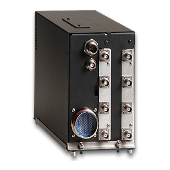
- Page 163 KMH 880/KTA 870 Figure 3-21 KMH 820/KTA 810 Processor Front Connector Rev 0, October/2000 10609I00.ZIPCDL Page 3-95...
- Page 164 KMH 880/KTA 870 Figure 3-22 KMH 820/KTA 810 Front Connector Cable Page 3-96 10609I00.ZIPCDL Rev 0, October/2000...
- Page 165 KMH 880/KTA 870 Notes Future Use (Do Not Wire) Pin Description Unit POWER ON=GND TEST=GND FUNCTIONAL_TEST EXTENDED=GND LANDING_GEAR* AIR_GND* ON GND=GND VALID=GND DISPLAY_VALID* RADIO_ALT+ ANALOG RADIO_ALT- ANALOG ANALOG RAD_ALT_VAL GIL_ALT_A4 BOTH 10 GIL_ALT_A2 BOTH 11 GIL_ALT_A1 BOTH 12 GIL_ALT_B4 BOTH 13 GIL_ALT_B2 BOTH 14 GIL_ALT_B1...
- Page 166 KMH 880/KTA 870 NOTES Future Use (Do Not Wire) Pin Description Unit 49 ATE_D(4) 50 ATE_D(5) 51 ATE_D(6) 52 ATE_D(7) 53 CALENB* 54 CDU_429_TX_A BOTH 55 CDU_429_TX_B BOTH 56 RAD_ALTIM_RX_A 57 RAD_ALTIM_RX_B 58 n/c 59 AIRCRAFT POWER 60 BARO_ALT_RX_A BOTH 61 BARO_ALT_RX_B BOTH 62 HDG_ATT_RX_A...
- Page 167 KMH 880/KTA 870 NOTES Future Use (Do Not Wire) Pin Description Unit 429RX_2A EGPWS 429RX_2B EGPWS RS232TXD_MON EGPWS MONITOR PORT *** MONITOR PORT 100 RS232RXD_MON EGPWS 101 ATE_CLOCK 102 n/c PICT BUS 103 ASPB_1A EGPWS 104 ASPB_1B EGPWS PICT BUS CM DATA OUT 105 SPIMOSI_CM_2 EGPWS...
- Page 168 KMH 880/KTA 870 THIS PAGE IS RESERVED Rev 0, October/2000 10609I00.ZIPCDL Page 3-100...
- Page 169 KMH 880/KTA 870 SECTION IV POST INSTALLATION CONFIGURATION AND CHECK OUT INTRODUCTION ................LINE SELECT KEYS ................ CONFIGURATION PROCEDURE ............ 4.2.1 Power On ..................4.2.2 Aircraft Configuration ................ 4.2.3 EGPWS Configuration Instructions............ 4.2.3.1 Equipment needed................4.2.3.2 Configuration Module Programming ..........4.2.3.3 Configuration String Format...............
- Page 170 KMH 880/KTA 870 LIST OF TABLES Table 4-1 Configuration Identification .............. Table 4-2 Aircraft/Mode Type Select ............... Table 4-3 Air Data Input Select................ Table 4-4 Position Input Select ................ Table 4-5 Terrain Display Select..............Table 4-6 Input/Output Discrete Type Select ........... Table 4-7 Audio Menu Select................
-
Page 171: Introduction
KMH 880/KTA 870 SECTION IV POST INSTALLATION CONFIGURATION AND CHECK OUT INTRODUCTION This Section describes the procedure for configuring and testing the KMH 880/KTA 870 System after it is installed in the aircraft. POST CONFIGURATION TEST This Post-Installation Test verifies the proper operation of the KMH 880/KTA 870 System. These procedures are used after the units have been initially installed. -
Page 172: Equipment Needed
EGPWS Installed and Operating Interconnect Cable IBM or Compatible PC A Copy of Honeywell WINVIEWS NOTE WinViews is an Enhanced GPWS diagnostic communications program that runs from Windows on a PC that is connected to the EGPWS. WinViews HELP , as well as many other menu items are active even though the program is fully oper- ational when communications are established with the EGPWS. - Page 173 KMH 880/KTA 870 Example String: = CUW 0/901000220/ (Space after cuw, category and each number if there is no separator) Where the first 0 reflects the string version, the next number is the number of categories and the remaining numbers before the second separator reflect the ID for each of the categories.
-
Page 174: Configuration Sequence Of Events
KMH 880/KTA 870 4.2.3.5 Configuration Sequence of Events (Application) Turn the KMH 880 system power on. Bring up the WINVIEWS program. Type Ctrl Z. At the WINVIEWS prompt type “CFG”. Press the ENTER key. Type in the pre-configured STRING using the command “CUW”. Press the ENTER key. - Page 175 KMH 880/KTA 870 This table provides the procedure to determine the Configuration ID selection required for any given aircraft installation. STEP SIGNAL IDENT. INSTRUCTION (CATEGORY) SELECTION Selects: Using Table 4-2 and any sub-tables Record the Ident (ID a) Aircraft Type contained within, locate the Air- No.) on the space _____...
-
Page 176: Configuration Tables
KMH 880/KTA 870 STEP SIGNAL IDENT. INSTRUCTION (CATEGORY) SELECTION Selects: Using Table 4-9 and any sub-tables Record the Ident (ID a) Altitude Monitor contained within, select the desired No.) on the space Display Disable True or False Condition for Altitude available on Ident b) Altitude Monitor Monitor Display Disable, Altitude... -
Page 177: Category 2, Air Data Input Select
KMH 880/KTA 870 NOTE When selecting ID 0; Category 6, (Audio Menu Select) must select ID #1 (Alter- nate) in order to be in compliance with TSO-C151a. 4.2.3.8.2 Category 2, Air Data Input Select The following table provides identification of the Air Data source type. In this category only the following parameters are to be defined: •... -
Page 178: Category 4, Terrain Display Select
UNS-1 GPS (GPS-1000 engine in the UNS-1B+,-1C, -1D, -1k,and -1M) sources are of WGS-84 type. NOTE 2 This configuration is only applicable to Honeywell Qualification Test Lab. When this configuration is enabled on a 066-01175-2101 (EGPWS with internal GPS) a software internal GPS monitor is activated for testing. -
Page 179: Category 5, Input/Output Discrete Type Select
KMH 880/KTA 870 In this category the following signals are configured by the ID number: SIGNAL NAME SIGNAL TYPE DEFINED BY Terrain Display Bus ASPB or ARINC Display configuration Group Range Bus ARINC 429 Display Input Control Group TA&D Alternate Pop Up Boolean Defined directly in Table 4-10 DISPLAY DISPLAY INPUT... - Page 180 KMH 880/KTA 870 NOTE If a single cockpit lamp is desired for Terrain Cautions and Warnings, J10-116 and J10-117 can be diode or’ed together to drive one lamp. 4.2.3.8.6 Category 6, Audio Menu Select The following table provides identification of the Voice Menu type. AUDIO MENU TYPE DESCRIPTION EFFECTIVITY...
-
Page 181: Category 8, Altitude Monitor Options
KMH 880/KTA 870 VOLUME TYPE EFFECTIVITY App. Cfg. Max (600 ohm ≈ 100mW) -001 -001 -6 dB -001 -001 -12dB -001 -001 -18dB -001 -001 -24dB -001 -001 -14db for ΚΜΗ 880/ΚΤΑ 870 configuration -001 -001 Table 4-8 Audio Output level 4.2.3.8.8 Category 8, Altitude Monitor Options The following table provides identification of the Altitude Monitor Options. -
Page 182: Tas Configuration Options
KMH 880/KTA 870 TA&D Alternate Pop Up = True disables the automatic Pop Up feature. TA&D ALTERNATE POP UP DISABLE EFFECTIVITY False -001 -001 True -001 -001 Table 4-10 Terrain Display Alternate Pop Up Option 4.2.4 TAS Configuration Options The TAS Processor will acquire the following hardware strap information from the configuration module. - Page 183 KMH 880/KTA 870 Radio Altimeter Type; Not Installed, ARINC 429, Bendix/King Analog, Sperry Analog, Collins Analog or ARINC 552A. The Radio Altimeter Source Port will input to the TAS Processor. The input impedance into this port is 55 Kohms. The port has an associated Radio Altitude Valid flag input to the TAS Processor.
- Page 184 The ATE Output will be used to enable the ATE lines for the Anechoic Chamber and the RGS stations. Intruder File Protocol ARINC 735a or Honeywell Business and Commuter Aviation Systems (BCAS) protocol. Display Valid Input Usage: Used or Ignored.
-
Page 185: Tas Rs-232 Maintenance Port
4.2.4.2 TAS RS-422 Data Recorder One port is provided which meets the characteristics specified in EIA RS-422A. This bus can be used as a data recording vehicle. It need not be wired unless requested by Honeywell personnel. Maximum Recommended Cable Length 15 Feet... -
Page 186: Egpws Ground Test Procedures
EGPWS Ground Test Procedures (066-01175-x101 only). This Ground Test Procedure is designed to minimize potential equipment dam- age and verify proper operation of the Honeywell EGPWS as installed in the air- craft. Review your aircraft installation drawings against the manufacturer’s data sheets and verify that all necessary connections are included on your draw- ings and that the pin numbers are in agreement. - Page 187 KMH 880/KTA 870 Now press function key F6 on your keyboard. Set the aircraft’s altimeter to 29.92 IN Hg and note the altitude displayed on the altimeter. Now look at the PC screen and locate the item named Gill- ham Alt ft. and verify that the altitude shown agrees with the aircraft altime- ter, ±...
- Page 188 KMH 880/KTA 870 Set the pitot-stat test set to -1000 feet, exercise caution to avoid excessive pressure changes to the static system of the aircraft. Verify that the PC dis- play shows the item named Gillham Alt ft. at -1000 feet ± 100 feet. Set up the pitot-static test set to allow an ascent to 30,000 feet, or to the maximum altitude of the lowest rated device attached to the static system.
- Page 189 KMH 880/KTA 870 To check the aircraft system interconnections, perform the following: Check that all cables and interwiring are installed according to the Interwir- ing and Cable Fabrication instructions. (paragraph 2.2.7 and 2.2.8) Check that the following functions are properly strapped to reflect the air- craft system configuration.
- Page 190 KMH 880/KTA 870 Check that the aircraft 5Vac or Vdc or 28 Vdc panel background lighting power source and dimmer control is operational by adjusting the cockpit dimmer switch for proper cockpit panel background illumination. Check that the Transponder, TAS, and Radar Systems are OFF. If applica- ble, the selected encoding altitude source should be #1.
- Page 191 KMH 880/KTA 870 the word “TEST” is displayed on the display. The following symbols are dis- played: • Traffic Advisory (yellow circle) will appear at 9 o’clock, range of 2 miles, 200 feet below and climbing. • Proximity traffic (solid white diamond) will appear at 1 o’clock, range 3.6 miles, 1000 feet below and descending.
- Page 192 KMH 880/KTA 870 Pass/Fail _____ NOTE The following three steps should only be performed when the configuration mod- ule is set to use the Display Valid input. Pull the Traffic Display circuit breaker. NOTE The above circuit breaker should be for the unit providing a valid to the TAS Pro- cessor at pin 5.
- Page 193 KMH 880/KTA 870 Pass/Fail _____ Test the ABOVE/NORMAL/BELOW function as follows: On the TAS Control Panel, set the ABOVE/NORMAL/BELOW to ABOVE. On the traffic display screen, “ABOVE” should be annunciated. Traffic between 2700 feet below and 8700 feet above can be displayed. Select BELOW.
- Page 194 Pass/Fail _____ If applicable (-0901 and -1001 versions of the CP 66B with a Honeywell Multi-Functional Display), check that the display modes can be selected properly via the MAN_AUTO discrete as follows: Via the separate Man/Auto switch, ground MAN_ AUTO,...
- Page 195 KMH 880/KTA 870 Pass/Fail _____ If applicable, check that the traffic modes (T/WX) can be selected on the color radar indicator as follows: Set the T/WX switch to indicate “WX” (Weather Only). Observe that the traffic display (radar indicator) annunciates “TA AUTO”, but unless TA traffic is present only the radar picture is displayed.
- Page 196 KMH 880/KTA 870 Verify that the Heading Status goes INVALID. Verify that the “TAS” flag appears on the traffic display. Reset the circuit breaker. Verify that the TAS flag clears. Pass/Fail ______ Verify that the encoding altitude is properly interfaced to the TAS Processor.
- Page 197 KMH 880/KTA 870 Transponder indicates ______ feet. Altitude at 31,800 feet, the computer screen indicates ______ feet. Transponder indicates ______ feet. NOTE The above test step checks both logic states for all Gillham lines. Other tests may be adequate for some installations. Flag the encoding altitude source by pulling the circuit breaker.
- Page 198 KMH 880/KTA 870 Verify that the Pitch and Roll Status goes INVALID. Verify that the “TAS” flag appears on the traffic display. Reset the circuit breaker. Verify that the “TAS” flag clears. Pass/Fail ______. If applicable, verify that the Radio Altimeter is properly interfaced to the TAS Processor.
- Page 199 KMH 880/KTA 870 When the Radio altitude is at 2,500 feet, the Diagnostic Computer indicates ______ feet. Flag the Rad. Altitude source by pulling the circuit breaker. Verify that the Rad. Alt. Status goes INVALID. Verify that the “TAS” flag appears on the traffic display. Reset the circuit breaker.
- Page 200 KMH 880/KTA 870 The HEX value of the bottom directional antenna elements should indicate as described above. The value of the monopole antenna elements (J2-J4) should indicate between 00 H and 93 H. antenna, Do all items Pass/Fail ______? Perform the Ramp test. This test requires the use of a TCAS Ramp Tester.
- Page 201 KMH 880/KTA 870 Using TASDIAG, enable the “Ramp Tester Mode under the “File” drop down menu. NOTE Once “Ramp Tester Mode” is entered, power must be cycled on the KMH/KTA before any flight Set up the TCAS Ramp Test Set. Using the TCAS Ramp test set, create a scenario to simulate an approaching Mode C transponder equipped aircraft beginning at 10 NM, at an altitude of 20,500 feet, at a closure rate of +450 KTS and an...
- Page 202 KMH 880/KTA 870 Another test to check the Advisory Inhibit Inputs can be performed with the Diagnostic Computer. Initiate the TAS self-test. As soon as the “TAS SYSTEM TEST OK” message begins, press the GPWS Test switch or simulate a GPWS advisory. TAS audio is interrupted.
- Page 203 KMH 880/KTA 870 When checking the bottom antenna bearing accuracy, the relative altitude difference between the simulated intruder and own aircraft altitude should be -6,000 feet (or more). The test antenna should be below the mounting plane of the bottom directional antenna. Position the aircraft outside on a heading of north away from hangers and other aircraft.
- Page 204 KMH 880/KTA 870 Figure 4-1 TAS Bearing Measurements NOTE Bearing Error equals the heading to TCAS Ramp Tester less the relative bearing of intruder. Relative bearing to the intruder should be a positive number mea- sured clockwise from north on the traffic display unit. Page 4-34 10609I00.ZIPCDL Rev 0, October/2000...
- Page 205 KMH 880/KTA 870 NOTE The largest acceptable TAS bearing error is +/- 30° except between 135° and 225° (aft of the wings) where the error may be 45°. 11. Perform the Power and Frequency tests shown in the TAS Operator’s Guide.
- Page 206 KMH 880/KTA 870 THIS PAGE IS RESERVED Rev 0, October/2000 10609I00.ZIPCDL Page 4-36...
- Page 207 KMH 880/KTA 870 SECTION V CERTIFICATION INTRODUCTION ................. CERTIFICATION PROCEDURE ............5.1.1 Equipment Compatibility ..............5.1.2 Equipment Location ................5.1.3 Federal Communication Commission Rules ........5.1.4 TSO Category ..................5.1.5 FTZ Requirement ................5.1.6 FAA Requirements ................5.1.7 FAA Form 337 ..................5.1.8 Flight Manual Revision ................
- Page 208 KMH 880/KTA 870 THIS PAGE IS RESERVED Rev 0, October/2000 10609I00.ZIPCDL TOC 5-ii...
-
Page 209: Certification
KMH 880/KTA 870 SECTION V CERTIFICATION INTRODUCTION This section outlines the procedures required to obtain IFR certification for the KMH 880/ KTA 870 System. Recommended flight test procedures are also included. CERTIFICATION PROCEDURE 5.1.1 Equipment Compatibility Careful consideration must be paid to the electrical characteristics of existing equipment or possible additions that will be interfaced with the KMH 880/KTA 870 System, in order to ensure system compatibility. -
Page 210: Federal Communication Commission Rules
KMH 880/KTA 870 5.1.3 Federal Communication Commission Rules The equipment will comply with all applicable rules of the Federal Communica- tion Commission. 5.1.4 TSO Category All aircraft, which are required by Federal Aviation Regulations to have a Ter- rain Awareness and Warning System complying with TSO C151a Class B, must be configured with the TSO curves. -
Page 211: Flight Manual Revision
KMH 880/KTA 870 5.1.8 Flight Manual Revision A Flight Manual Supplement is usually required for approval. A sample supple- ment is provided in the Flight Manual Supplement Appendix of this manual. The sample is to be used as a guide to acceptable content and format, and not intended to apply to all installations. - Page 212 KMH 880/KTA 870 THIS PAGE IS RESERVED Page 5-4 10609I00.ZIPCDL Rev 0, October/2000...
- Page 213 KMH 880/KTA 870 SECTION VI OPERATION INTRODUCTION..................Rev 0, October/2000 10609I00.ZIPCDL TOC 6-i...
- Page 214 KMH 880/KTA 870 THIS PAGE IS RESERVED Rev 0, October/2000 10609I00.ZIPCDL TOC 6-ii...
- Page 215 KMH 880/KTA 870 SECTION VI OPERATION INTRODUCTION Refer to Section IV, of this manual, for the operating instructions for the post installation checkout. Refer to the KMH 880/KTA 870 System Operator’s Manual P/N 006-18265- 0000, for complete operating instructions. Rev 0, October/2000 10609I00.ZIPCDL Page 6-1...
- Page 216 KMH 880/KTA 870 THIS PAGE IS RESERVED Page 6-2 10609I00.ZIPCDL Rev 0, October/2000...
- Page 217 KMH 880/KTA 870 APPENDIX A Antenna Surveillance Range Rev 0, October/2000 10609I00.ZIPCDL Page A-1...
- Page 218 KMH 880/KTA 870 Page A-2 10609I00.ZIPCDL Rev 0, October/2000...
- Page 219 KMH 880/KTA 870 THIS PAGE IS RESERVED Rev 0, October/2000 10609I00.ZIPCDL Page A-3...
- Page 220 KMH 880/KTA 870 APPENDIX B STC Appendix Rev 0, October/2000 10609I00.ZIPCDL Page STC-1...
- Page 221 KMH 880/KTA 870 Information to be added, if required. Page STC-2 10609I00.ZIPCDL Rev 0, October/2000...
- Page 222 KMH 880/KTA 870 APPENDIX C CERTIFICATION APPENDIX SAMPLE CERTIFICATION CHECKLIST Rev 0, October/2000 10609I00.ZIPCDL Page CERT-1...
- Page 223 KMH 880/KTA 870 THIS PAGE IS RESERVED Page CERT-2 10609I00.ZIPCDL Rev 0, October/2000...
- Page 224 KMH 880/KTA 870 SAMPLE CERTIFICATION CHECKLIST AIRCRAFT MAKE: _______________________________ AIRCRAFT MODEL: _______________________________ AIRCRAFT SERIAL NUMBER: _______________________________ AIRCRAFT REGISTRATION NUMBER: _______________________________ DATE WORK COMPLETED: _______________________________ A. Installed the KMH 880/KTA 870 System in accordance with Unit Installation Manual number 006-10609-000_, Revision ____, dated __________, and has been flight tested in accordance with AC20-ZZ (draft), to verify proper operation and accuracy for a follow-on IFR approval.
- Page 225 KMH 880/KTA 870 THIS PAGE IS RESERVED Page CERT-4 10609I00.ZIPCDL Rev 0, October/2000...
- Page 226 KMH 880/KTA 870 APPENDIX D DIAGNOSTIC APPENDIX Rev 0, October/2000 10609I00.ZIPCDL...
- Page 227 KMH 880/KTA 870 THIS PAGE IS RESERVED 10609I00.ZIPCDL Rev 0, October/2000...
- Page 228 KMH 880/KTA 870 DIAGNOSTIC APPENDICES TASDIAG-TAS Processor Field Diagnotic Program User Instructions WARNING: DO NOT USE THE “TASDIAG PROCESSOR FIELD DIAGNOSTIC PROGRAM” WHILE AIRBORNE. THE PROGRAM IS USED ONLY WHILE THE AIR- CRAFT IS ON THE GROUND. THE SYSTEM IS DEGRADED TO PERFORM MAINTE- NANCE FUNCTIONS AND IS NOT AIRWORTHY WHILE RUNNING THE DIAGNOSTIC SOFTWARE.
- Page 229 KMH 880/KTA 870 THIS PAGE IS RESERVED 10609I00.ZIPCDL Rev 0, October/2000...
- Page 230 KMH 880/KTA 870 ____________________________________________________________________ Honeywell International Inc. P/N 700-01055-0000 TAS Diag for Windows User Manual Revision- Page 1 of 18 10609I00.ZIPCDL Rev 0, October/2000...
- Page 231 KMH 880/KTA 870 THIS PAGE IS RESERVED ____________________________________________________________________ Honeywell International Inc. P/N 700-01055-0000 TAS Diag for Windows User Manual Revision- Page 2 of 18 10609I00.ZIPCDL Rev 0, October/2000...
- Page 232 11. TAS S/W Info ......................14 12 Ramp Tester Mode .....................14 13 Suggestions and Hints..................14 13.1 TAS Diag Doesn’t Communicate with TAS Unit ........14 ____________________________________________________________________ Honeywell International Inc. P/N 700-01055-0000 TAS Diag for Windows User Manual Revision- Page 3 of 18 10609I00.ZIPCDL...
-
Page 233: Introduction
The following Part Numbers identify the TAS Diag program and documentation: 700-01055-0000 User Manual (this documentation) 731-30007-0000 CD-ROM containing TAS Diag for Windows and User Manual ____________________________________________________________________ Honeywell International Inc. P/N 700-01055-0000 TAS Diag for Windows User Manual Revision- Page 4 of 18 Rev 0, October/2000 10609I00.ZIPCDL... -
Page 234: Computer Requirements
TAS Diag COM port properties The TAS Diag program is started by selecting the “TAS Diag for Windows” icon in the “Start-Programs-TAS Diag’ group. ____________________________________________________________________ Honeywell International Inc. P/N 700-01055-0000 TAS Diag for Windows User Manual Revision- Page 5 of 18 10609I00.ZIPCDL... - Page 235 The menu and button bars contain the available options for the TAS Diag program. WARNING TAS Diag is not intended for use during flight. ____________________________________________________________________ Honeywell International Inc. P/N 700-01055-0000 TAS Diag for Windows User Manual Revision- Page 6 of 18 Rev 0, October/2000 10609I00.ZIPCDL...
-
Page 236: Tas Diag Demonstration Mode
On the I/O Data menu, click Snapshot View to request a snapshot ( one time) of the I/O Data. The TAS unit sends the data to the “Main Diagnotic Window”. ____________________________________________________________________ Honeywell International Inc. P/N 700-01055-0000 TAS Diag for Windows User Manual... -
Page 237: Continous View
Log Data. The TAS unit sends the data to the “Main Diagnostic Window” ( see Figure 3). Figure 3 Diagnostic and Log Data Window ____________________________________________________________________ Honeywell International Inc. P/N 700-01055-0000 TAS Diag for Windows User Manual Revision- Page 8 of 18 Rev 0, October/2000 10609I00.ZIPCDL... -
Page 238: Configuration Module Options
This option allows the user to view the current strap settings in an easy to read lay- out. The TAS unit sends the data to the “Main Diagnostic Window” ( see Figure 4). Figure 4 View Strap Data Window ____________________________________________________________________ Honeywell International Inc. P/N 700-01055-0000 TAS Diag for Windows User Manual Revision-... -
Page 239: Modify Strap Data
At this point the user may click the OK button to continue. Figure 5 Modify Straps Window ____________________________________________________________________ Honeywell International Inc. P/N 700-01055-0000 TAS Diag for Windows User Manual Revision- Page 10 of 18 Rev 0, October/2000 10609I00.ZIPCDL... -
Page 240: Save To Text File
When the TAS unit is ini- tialized, a message will be displayed in the window for the user. At this point the user may click the OK button to continue. ____________________________________________________________________ Honeywell International Inc. P/N 700-01055-0000 TAS Diag for Windows User Manual Revision-... -
Page 241: Initialize Config Module
When the Strap configuration is complete, click the OK button to save it to the con- figuration module. ____________________________________________________________________ Honeywell International Inc. P/N 700-01055-0000 TAS Diag for Windows User Manual Revision- Page 12 of 18 Rev 0, October/2000 10609I00.ZIPCDL... -
Page 242: Intruder Data
180 ( or - 180 ) degrees is at the 6 o’clock position, and - 90 is at the 9 o’clock position. A series of -----’s indicates that a bearing could not be determined for the intruder. ____________________________________________________________________ Honeywell International Inc. P/N 700-01055-0000 TAS Diag for Windows User Manual Revision-... -
Page 243: Overwrite View
TISIs have been captured, the updates are stopped. If the stop button on the but- ton bar is clicked, the updates will also stop before completion of the specified num- ber of TISIs. ____________________________________________________________________ Honeywell International Inc. P/N 700-01055-0000 TAS Diag for Windows User Manual Revision-... -
Page 244: Viewing Cable Calibration Data
34 seconds. To view the cable calibration data, View Data on the Cable Cal Menu (see Figure 8). Figure 8 Cable Calibration Data Window ____________________________________________________________________ Honeywell International Inc. P/N 700-01055-0000 TAS Diag for Windows User Manual Revision-... -
Page 245: Viewing Current System Status
Overwrite View on the Sys Status Menu. For continuously, click Con- tinuous View on the Sys Status Menu. Figure 9 System Status Window ____________________________________________________________________ Honeywell International Inc. P/N 700-01055-0000 TAS Diag for Windows User Manual Revision- Page 16 of 18 Rev 0, October/2000 10609I00.ZIPCDL... -
Page 246: Tas S/W Info
Ramp Tester Mode on the File Menu. When the option is on, a check mark appears to the left of Ramp Tester Mode on the File Menu. ____________________________________________________________________ Honeywell International Inc. P/N 700-01055-0000 TAS Diag for Windows User Manual Revision-... - Page 247 Comm Port and enable it for external communications. This is usually done in the “My Computer” properties or in the BIOS setting. You should call your computer manufacturer if you can not free up the port. ____________________________________________________________________ Honeywell International Inc. P/N 700-01055-0000 TAS Diag for Windows User Manual Revision-...
- Page 248 KMH 880/KTA 870 TSO APPENDIX ENVIRONMENTAL QUALIFICATION FORM Rev 0, October/2000 10609I00.ZIPCDL TSO-1...
- Page 249 KMH 880/KTA 870 THIS PAGE IS RESERVED TSO-2 10609I00.ZIPCDL Rev 0, October/2000...
- Page 250 050-03361-0000 Installation Kit 047-12545-0003 Mounting Tray TSO NUMBER: C147 (Class A), C151a (Class B) MANUFACTURER’S SPECIFICATION: MPS 004-02050-4000 MANUFACTURER: Honeywell International Inc. ADDRESS: One Technology Center 23500 W. 105 Street Olathe, KS 66061 CONDITIONS DO-160D SECTION DESCRIPTION OF CONDUCTED TESTS...
- Page 251 3. The unit shall comply with DO-160C, vibration category N and Y for helicopters. 4. RF susceptibility degradation information placed here if applicable. 5. The unit shall comply with A3E3 on all signal lines and A4E4 on the power leads. Honeywell International Inc. P/N 004-02050-4800 Environmental Qualification Form...
- Page 252 KMH 880/KTA 870 REVISION HISTORY Revision PRN/CO # Description of Change Date PRN ______ Original Issue Honeywell International Inc. P/N 004-02050-4800 Environmental Qualification Form Revision - Rev 0, October/2000 10609I00.ZIPCDL TSO-5...
- Page 253 KMH 880/KTA 870 THIS PAGE IS RESERVED TSO-6 10609I00.ZIPCDL Rev 0, October/2000...