Table of Contents
Quick Links
Table of Contents

Related Manuals for Bosch CCS800


Summary of Contents for Bosch CCS800
- Page 1 CCS800 Service manual en Discussion system...
-
Page 3: Important Safeguards
(instructions enclosed with the LBB 3310 delivery) • Proper service and repair is important for safe and reliable operation of all Bosch Security Systems equipment. • Some service operations require the use of tools specially designed for the purpose. These special tools should be used when recommended. -
Page 4: Table Of Contents
CCS800 | Service manual | Table of contents en | 2 Table of contents Important Safeguards ..............................1 General information............................5 Document history ..........................5 About this manual ..........................5 Related documentation ........................5 Alerts..............................5 Policy & Procedures ...........................5 1.5.1 Repair Policy..........................5 1.5.2 Warrantee conditions ......................5 1.5.3... - Page 5 Trunk cable interconnections.......................... 44 10.1 Pin numbers delegate- and chairman extension trunk cable ............44 10.2 LBB 3316/00 – CCS800 extension cable and connectors............45 Mounting instruction new CPSU board in old LBB 3310/00..............46 11.1 Needed tools and parts ........................46 11.2...
- Page 6 CCS800 | Service manual | Table of contents en | 4 Illustrations................................ 51 13.1 Exploded view CPSU ........................53 13.2 Board layout CPSU ......................... 54 13.3 Measuring points CPSU board ...................... 55 13.3.1 Bottom view CPSU board section mounted in top cover..........55 13.4...
-
Page 7: General Information
“Dead on Arrival” (DOA) products: For these products MDB/ Selectron will offer a replacement of a brand new product. MDB/ Selectron or BOSCH Security Systems Breda is free to credit you in case of any damage to the product, which is not reported by the NSO / BOSCH Security Systems Authorized service partner. -
Page 8: Service Period
BOSCH Security Systems. Other related costs for the corrective action have to be agreed upon by the NSO / service partner and BOSCH Security Systems service Breda. It is not allowed to start local corrective actions without consulting BOSCH Security Systems service Breda. -
Page 9: Example Rma Request Form
CCS800 | Service manual | Chapter 1 | General information en | 7 Example RMA request form Bosch Security Systems | 2005-01| 3922 880 21112... -
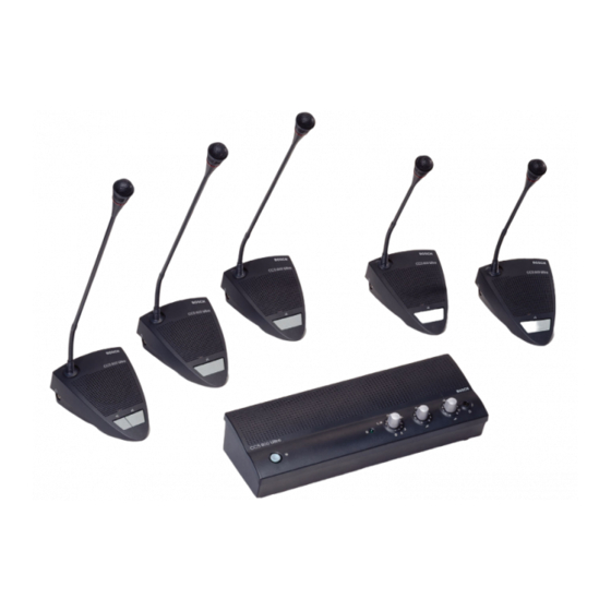
Page 10: Introduction
CCS800 | Service manual | Chapter 2 | Introduction en | 8 Introduction LBB 3310/00 Control and Power Supply Unit (CPSU) The CPSU is the heart of the discussion system, which controls the microphones of the chairman and delegate units as well as providing facilities for audio inputs and outputs. -
Page 11: Lbb 3310/10 Control And Power Supply Unit With Afs
CCS800 | Service manual | Chapter 2 | Introduction en | 9 LBB 3310/10 Control and Power Supply Unit with AFS This model CPSU has additional an Acoustic Feedback Suppression PCB inside. 2.2.1 Block diagram CPSU with AFS Bosch Security Systems | 2005-01| 3922 880 21112... -
Page 12: Audio Level Diagram Cpsu
CCS800 | Service manual | Chapter 2 | Introduction en | 10 2.2.2 Audio level diagram CPSU Bosch Security Systems | 2005-01| 3922 880 21112... -
Page 13: Afs Module Lbb 3310/10)
The firmware can configure the audio interface and perform simple control functions. The download of the firmware is performed in a factory environment. In CCS800 the module is included in the signal chain. After power-up the board will boot from the on-board boot-EEPROM, copy the program available in flash ROM into SDRAM, and execute the program code in SDRAM. -
Page 14: Lbb 3330/00 Delegate Unit
CCS800 | Service manual | Chapter 2 | Introduction en | 12 LBB 3330/00 Delegate Unit This unit provides the microphone, unit loudspeaker and headphones facilities for the delegates using the CCS 800 discussion system. The headphone connections are interconnected with the loudspeaker. When one or both headphone connections are used and the microphone is not on, the loudspeaker is switched OFF. -
Page 15: Lbb 3331/00 Chairman Unit
CCS800 | Service manual | Chapter 2 | Introduction en | 13 LBB 3331/00 Chairman Unit This unit provides the microphone, unit loudspeaker and headphones facilities for the chairman using the CCS 800 discussion system. Pressing the microphone button always activates the chairman microphone. Pressing the priority button will deactivated all active delegate units and activates the chairman’s microphone. -
Page 16: Audio Level Diagram Delegate And Chairman Units
CCS800 | Service manual | Chapter 2 | Introduction en | 14 Audio level diagram delegate and chairman units Bosch Security Systems | 2005-01| 3922 880 21112... -
Page 17: Controls And Indicators
CCS800 | Service manual | Chapter 3 | Controls and indicators en | 15 Controls and indicators Control and Power Supply Unit (CPSU) Function On/OFF button Switches the CPSU ON or OFF Green LED (B1) Indicates if the CPSU is switched ON or OFF Left rotary switch (S2) Microphone-mode switch. -
Page 18: Delegate And Chairman Units
CCS800 | Service manual | Chapter 3 | Controls and indicators en | 16 Delegate and chairman units Microphone Electret microphone with build-in plop and windshield, mounted on a flexible stem, complete with a red LED light-ring Light-ring around the microphone... -
Page 19: Technical Data
CCS800 | Service manual | Chapter 4 | Technical data en | 17 Technical data Power supply Specification Type of power supply: 40W single output, universal input switching power supply Mains input voltages: 90 .. 264Vac Input frequency range: 47 .. 63Hz Max. -
Page 20: Microphone Stem Adjustment
Measure the audio level on the AC meter. Take this level as ref. for the CCS800 units to be adjusted. Repeat the ref. measurement for a check with other unit(s). (The factory level adjustment is ± 1,5 dB) - Page 21 CCS800 | Service manual | Chapter 5 | Microphone stem adjustment en | 19 Remove the factory-adjusted unit and place the Do not change the audio setting adjustments. unit for adjustment in the same position. Read the audio level on the AC meter.
-
Page 22: Maintenance And Repair
CCS800 | Service manual | Chapter 6 | Maintenance and repair en | 20 Maintenance and repair 6.1.1 Preventive maintenance Regular preventive maintenance is not necessary. Depending on the usage the equipment may need cleaning. 6.1.2 Corrective maintenance Defective units can be repaired or temporary replaced by a new one. Recommended repair method is to use the centralized repair procedure (see chapters 1.5 and 1.6). -
Page 23: Diagnostics And Fault Finding
Brief description of the various modes of the chairman and delegate unit The CCS800 discussion system uses two control lines, CTRL-L1 and CTRL-L2. These two control lines are used to set the delegate and chairman units in a specific mode. Each mode depends of the position of the mode switch, located on the CPSU and pressing the microphone button or priority button on the delegate and chairman units. -
Page 24: Ctrl-L1
CCS800 | Service manual | Chapter 7 | Diagnostics and faultfinding en | 22 7.2.1 CTRL-L1 Depending of the voltage level of CTRL-L1 the ORM (override mode) is activated or the MAXNOM (maximum number of delegate microphones) is activated. 7.2.2... -
Page 25: Settings Before You Start Measuring
CCS800 | Service manual | Chapter 7 | Diagnostics and faultfinding en | 23 7.3.1 Settings before you start measuring • Set the insertion switch (S1), located at the rear side, to the left position (“1”). • Set the potentiometer of the headphone volume (R201) to maximum (fully clockwise). -
Page 26: Audio Contribution To Loudspeaker Measurement
CCS800 | Service manual | Chapter 7 | Diagnostics and faultfinding en | 24 7.3.5 Audio contribution to loudspeaker measurement Insert a sine wave signal to the AUDIO-CONTR via M1 related to M2 and measure the output signal between M59 and M57. -
Page 27: Audio Contribution To Audio Distribution Measurement
CCS800 | Service manual | Chapter 7 | Diagnostics and faultfinding en | 25 7.3.6 Audio contribution to audio distribution measurement Connect a sine-wave generator to one Trunk connectors (X2) M1 and measure the output signal at the other Trunk connector (X3) M3. -
Page 28: External Microphone Input To Line Out Measurement
CCS800 | Service manual | Chapter 7 | Diagnostics and faultfinding en | 26 7.3.7 External microphone input to line out measurement Connect successively a sine-wave generator to the left and right external microphone input connections, (“MIC-IN+” (M131) and “MIC-IN-” (M132) ) related to GND (M133). -
Page 29: Telephone-Out, Line-Out And Insertion-Out Measurement
CCS800 | Service manual | Chapter 7 | Diagnostics and faultfinding en | 27 7.3.8 Telephone-out, Line-out and Insertion-out measurement Connect a sine-wave generator to the LINE-IN connector and measure successively the output signal at the TELEPHONE-OUT (M109), LINE-OUT (M119) and INSERTION-OUT“ (M169) connector. -
Page 30: Line-In To Rec-Out Circuit Measurement
CCS800 | Service manual | Chapter 7 | Diagnostics and faultfinding en | 28 7.3.9 LINE-IN to REC-OUT Circuit measurement Connect a sine-wave generator to the LINE-IN connector and measure the output signal at the RECORDER-OUT (M129) connector. Input setting G1: M110 related to M111 (GND), see table below. -
Page 31: Recorder-In To Line-Out Measurement
CCS800 | Service manual | Chapter 7 | Diagnostics and faultfinding en | 29 7.3.10 Recorder-in to Line-out measurement Remove the interconnections of REC-IN-L and REC-IN-R and connect successively a sine-wave generator to the REC-IN- L and REC-IN-R connector. Measure the output signal at the LINE-OUT connector. -
Page 32: Telephone-In To Line-Out Circuit Measurement
CCS800 | Service manual | Chapter 7 | Diagnostics and faultfinding en | 30 7.3.11 TELEPHONE-IN to LINE-OUT Circuit measurement Remove the interconnections of TELEPHONE -IN and connect successively a sine-wave generator to the TELEPHONE - IN L connector. Measure the output signal at the LINE-OUT connector. -
Page 33: Control Line Test With Mode Switch (A)
CCS800 | Service manual | Chapter 7 | Diagnostics and faultfinding en | 31 7.3.12 Control line test with mode switch (A) By use of a combination of different voltage levels at CTRL-L1 and CTRL-L2 each mode of the CPSU can be passed on to the Delegate and Chairman units. -
Page 34: Control Line Test With Mode Switch (B)
CCS800 | Service manual | Chapter 7 | Diagnostics and faultfinding en | 32 7.3.13 Control line test with mode switch (B) Connect a current source of 0.5mA ±0.03mA to the control-line CTRL-L1 via M4 Set the “mode switch” (S2) is each... -
Page 35: System Volume Control Test
CCS800 | Service manual | Chapter 7 | Diagnostics and faultfinding en | 33 7.3.14 System volume control test Measure the output level related to each position of the volume control (S3) for the loudspeakers of the Delegate and Chairman units. -
Page 36: Audio Control In To Line-Out Via Afs Circuit Of Cpsu Measurement
CCS800 | Service manual | Chapter 7 | Diagnostics and faultfinding en | 34 7.3.15 AUDIO CONTROL IN to LINE-OUT via AFS circuit of CPSU measurement (LBB 3310/10 only) Connect a sine-wave generator to one Trunk connectors (X2) M1 and measure the output signal at output LINE-OUT (M119). -
Page 37: Functional Afs Test Of The Lbb 3310/10
• Switch On AFS, feedback audio stops. Not correct operating AFS board. If the AFS board not operates as above described, send the board (or CPSU) to the Bosch central repair facility. Note Valid for LBB3310/10 (with AFS) only. Be sure that the cable clamp on the flat cable (CPSU board – upper housing board) is correctly mounted. -
Page 38: Measuring Spots Cpsu Board With Signal Description
CCS800 | Service manual | Chapter 7 | Diagnostics and faultfinding en | 36 Measuring spots CPSU board with signal description See chapter 13.3 for location on the board. Measuring spots Signal AUDIO-CONTR AUDIO-DISTR CTRL-L1 CTRL-L2 SUPP +24V +15V +7.5V... -
Page 39: Measuring Instructions For The Delegate And Chairman Unit
CCS800 | Service manual | Chapter 7 | Diagnostics and faultfinding en | 37 Measuring instructions for the Delegate and Chairman unit How to check if a Delegate or Chairman unit operates correct is described in the next paragraphs. Supply current 7.5.1... -
Page 40: Internal Signals Only For Delegate Units
CCS800 | Service manual | Chapter 7 | Diagnostics and faultfinding en | 38 7.5.6.2 TEST mode Set the Mode switch at the CPSU successively in the Test and Auto mode. Measure the DC-voltage via M31 related to M8 (0V). -
Page 41: Chairman Only Mode
CCS800 | Service manual | Chapter 7 | Diagnostics and faultfinding en | 39 7.5.8 Chairman Only mode Set the Mode switch at the CPSU successively in the Test and Chairman Only mode. Measure the DC-voltage via M33 related to M8 (0V). -
Page 42: Measuring Spots Delegate And Chairman Board With Signal Description
CCS800 | Service manual | Chapter 7 | Diagnostics and faultfinding en | 40 Measuring spots Delegate and Chairman board with signal description See chapter 13.11 for location on the boards. Measuring spots Signal Delegate Chairman AUDIO-CONTR System GND AUDIO-DISTR... -
Page 43: New Microphone Assembly On An Old Delegate-/ Chairman Unit
CCS800 | Service manual | Chapter 8 | New mic assy on an old del-/ chairman unit en | 41 New microphone assembly on an old delegate-/ chairman unit Note This chapter is applicable to delegate-/ chairman unit produced before April 2001 (week 0116). -
Page 44: Field Changes Of Components On The Main Board
CCS800 | Service manual | Chapter 8 | New mic assy on an old del-/ chairman unit en | 42 Field changes of components on the main board In case the microphone assembly has been replaced and light output of the led ring is too low in respect to the installed units, change the components R169 and R170 on the main board in order to increase the led current. -
Page 45: Replacement Of The Microphone Capsule
CCS800 | Service manual | Chapter 9 | Replacement of the microphone capsule en | 43 Replacement of the microphone capsule See chapter 13.15 for the exploded view of the microphone head assembly and chapter 12.4 for the ordering numbers. -
Page 46: Trunk Cable Interconnections
CCS800 | Service manual | Chapter 10 | Trunk cable interconnections en | 44 Trunk cable interconnections 10.1 Pin numbers delegate- and chairman extension trunk cable Pin number Function Color Audio contribution White Coax shields 2x Audio distribution Violet Control line -1... -
Page 47: Lbb 3316/00 - Ccs800 Extension Cable And Connectors
CCS800 | Service manual | Chapter 10 | Trunk cable interconnections en | 45 10.2 LBB 3316/00 – CCS800 extension cable and connectors CCS800 trunk cable Bosch type nr Bosch code nr. Installation cable 6mm Ø, LBB 3316/00 8900 331 60005... -
Page 48: Mounting Instruction New Cpsu Board In Old Lbb 3310/00
The CPSU board layout and mounting holes of the ‘Bosch’ version is different from the old ‘Philips’ one. In case a new model ‘Bosch’ CPSU board have to be mounted in an old ‘Philips’ LBB 3310/00, follow the modification instructions explained below. -
Page 49: Spare Parts
12.1.1 Ordering spare parts Spare parts can be ordered with there unique Service code number through the local Bosch representative. Contact the local Bosch representative in case of questions/ remarks about e.g. availability, ordering/ supply procedures, prices, complaints, replacements, etc. -
Page 50: Lbb 3310/X0 Cpsu - Printed Board Spare Parts
5322 442 01417 Upper housing delegate ccs800 incl. mic. Knob – Bosch 3922 156 27800 Upper housing chairman ccs800 incl. mic. & prior. knob – Philips 5322 442 01418 Upper housing chairman ccs800 incl. mic. & prior. knob – Bosch... -
Page 51: Lbb 3330/X0 Delegate Unit - Service Assemblies Lbb 3331/X0 Chairman Unit - Service Assemblies
CCS800 | Service manual | Chapter 12 | Spare parts en | 49 Damping foam disc for loudspeaker 5322 466 11983 Trunk cable assembly male 7p CCS800 – Bosch 5322 320 12374 12.3.2 LBB 3330/x0 Delegate unit – Service assemblies LBB 3331/x0 Chairman unit –... -
Page 53: Illustrations
CCS800 | Service manual | Chapter 13 | Illustrations en | 51 Illustrations Index 13.1 Exploded view CPSU. 13.2 Board layout CPSU. 13.3 Measuring points CPSU board. 13.3.1 Bottom view CPSU board section mounted in top cover. 13.4 Circuit diagrams CPSU (sh 1/4) — Supply and logic. -
Page 55: Exploded View Cpsu
CCS800 | Service manual | Chapter 13 | Illustrations en | 53 13.1 Exploded view CPSU Bosch Security Systems | 2003-50 | 3922 880 21112... -
Page 56: Board Layout Cpsu
CCS800 | Service manual | Chapter 13 | Illustrations en | 54 13.2 Board layout CPSU Bosch Security Systems | 2003-50 | 3922 880 21112... -
Page 57: Measuring Points Cpsu Board
CCS800 | Service manual | Chapter 13 | Illustrations en | 55 13.3 Measuring points CPSU board For measuring points description CPSU board, see chapter7.4. The blue coloured measuring spots are supply voltages described in chapter’s 7.3.2 and 7.3.3 The yellow coloured measuring points are mentioned in the tests described in chapter’s 7.3.5 till 7.3.15. -
Page 58: Circuit Diagrams Cpsu (Sh 1/4) - Supply And Logic
CCS800 | Service manual | Chapter 13 | Illustrations en | 56 13.4 Circuit diagrams CPSU (sh 1/4) — Supply and logic Bosch Security Systems | 2003-50 | 3922 880 21112... -
Page 59: Circuit Diagrams Cpsu (Sh 2/4) - Gain Control And Mode Select
CCS800 | Service manual | Chapter 13 | Illustrations en | 57 13.5 Circuit diagrams CPSU (sh 2/4) — Gain control and mode select Bosch Security Systems | 2003-50 | 3922 880 21112... -
Page 60: Circuit Diagrams Cpsu (Sh 3/4) - Audio Input And Output
CCS800 | Service manual | Chapter 13 | Illustrations en | 58 13.6 Circuit diagrams CPSU (sh 3/4) — Audio input and output Bosch Security Systems | 2003-50 | 3922 880 21112... -
Page 61: Circuit Diagrams Cpsu (Sh 4/4) - External Microphone Input
CCS800 | Service manual | Chapter 13 | Illustrations en | 59 13.7 Circuit diagrams CPSU (sh 4/4) — External microphone input Bosch Security Systems | 2003-50 | 3922 880 21112... -
Page 62: Board Layout Afs Pcb
CCS800 | Service manual | Chapter 13 | Illustrations en | 60 13.8 Board layout AFS PCB 13.8.1 Jumpers and connectors J300 Horizontal placed J302 Vertical placed Jumper position Function Jumper position Function Input1 CCS800 Analog audio input Input1 CCS800... -
Page 63: Exploded View Delegate/ Chairman Unit
CCS800 | Service manual | Chapter 13 | Illustrations en | 61 13.9 Exploded view delegate/ chairman unit Bosch Security Systems | 2003-50 | 3922 880 21112... -
Page 64: Board Layout Delegate Unit
CCS800 | Service manual | Chapter 13 | Illustrations en | 62 13.10 Board layout delegate unit Bosch Security Systems | 2003-50 | 3922 880 21112... -
Page 65: Measuring Points Delegate And Chairman Unit
CCS800 | Service manual | Chapter 13 | Illustrations en | 63 13.11 Measuring points delegate and chairman unit Bosch Security Systems | 2003-50 | 3922 880 21112... -
Page 66: Circuit Diagram Delegate Unit
CCS800 | Service manual | Chapter 13 | Illustrations en | 64 13.12 Circuit diagram delegate unit Bosch Security Systems | 2003-50 | 3922 880 21112... -
Page 67: Board Layout Chairman Unit
CCS800 | Service manual | Chapter 13 | Illustrations en | 65 13.13 Board layout chairman unit Bosch Security Systems | 2003-50 | 3922 880 21112... -
Page 68: Circuit Diagram Chairman Unit
CCS800 | Service manual | Chapter 13 | Illustrations en | 66 13.14 Circuit diagram chairman unit Bosch Security Systems | 2003-50 | 3922 880 21112... -
Page 69: Microphone Assembly
CCS800 | Service manual | Chapter 13 | Illustrations en | 67 13.15 Microphone assembly 13.15.1 Exploded view microphone head 13.15.2 Led diagram and board layout 13.15.3 Wiring of the microphone assembly Bosch Security Systems | 2003-50 | 3922 880 21112... - Page 72 Bosch Security Systems B.V. Business Unit Communication Systems P.O. Box 90106 4800 RA Breda The Netherlands www.boschsecuritysystems.com © 2003 Bosch Security Systems B.V. Data subject to change without notice 3922 880 21112 – revision 01-0501...