
Related Manuals for Yamaha 6YC INFORMATION STATION

Summary of Contents for Yamaha 6YC INFORMATION STATION
- Page 1 6YC INFORMATION STATION OPERATION MANUAL 6YC-2819U-70-E0 Read this manual carefully before operation.
- Page 2 Read this manual carefully before operating the meter. Keep this manual onboard in a waterproof bag when boating. This manual should stay with the product if it is sold.
- Page 3 Thank you for selecting this product. This Operation Manual contains information needed for proper operation. A thorough understanding of these simple instructions will help you obtain maximum enjoyment from your new Yamaha. If you have any question about the operation of the meter, please consult a Yamaha dealer.
- Page 4 To the owner The 6YC Information Station enables the display of information through digital commu- nication with the engine. The description of optional parts in this man- ual, such as the speed sensor, cooling water pressure sensor, Multi sensor, GPS, and...
-
Page 5: Table Of Contents
Contents Alert Notifications ....1 MENU screen......19 Alert Notifications ......... 1 Switching the screens......19 Maintenance Notifications ....2 Features ..........20 Menu items ......... 21 General information....3 Resetting “Trip” information (Trip) ..21 List of abbreviations ......3 Managing the maintenance schedule (Maintenance) ........ -
Page 6: Alert Notifications
Alert Notifications Alert Notifications The multifunction display will notify the operator when engine abnormalities occur by display- ing a pop-up window and alert icon. A pop-up window will also be displayed when specific alert conditions occur. When events requiring multiple pop-up windows occur, the pop-up window with the highest degree of urgency is displayed first. -
Page 7: Maintenance Notifications
Alert Notifications Maintenance Notifications If this alert is displayed, carry out the maintenance and reset the maintenance schedule. See “Managing the maintenance schedule (Maintenance)” on how to reset the maintenance schedule (page 21). Maintenance alert Displayed when a scheduled maintenance is overdue. -
Page 8: General Information
General information General information List of abbreviations The following abbreviations are used in this manual. Abbreviations Descriptions ABYC American Boat and Yacht Council Europe Forward Global Positioning System Neutral Reverse Y-COP Yamaha Customer Outboard Protection... -
Page 9: Meter Unit
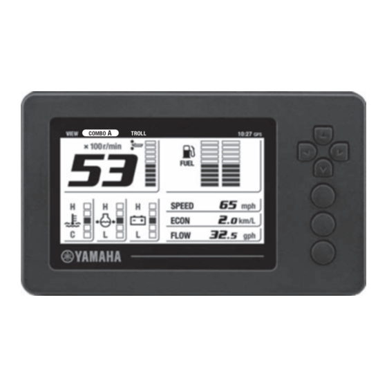
Meter unit Meter unit CANCEL MENU Name Explanation of function Displays the current time and the name of the currently selected main screen. Status bar (If no GPS is connected, the clock and the “GPS” icon will not be displayed.) •... - Page 10 Meter unit Name Explanation of function • Moves from any screen to the top “MENU” screen [MENU] button • Moves from the “MENU” screen or setting screen to the main screen...
-
Page 11: Initial Setting
Initial Setting Initial Setting The 6YC Information Station must be initial- 3. Set using the [SET] button. ized before its first use or after a reset oper- ation. TIP: Consult a Yamaha dealer when you perform the initial setting. Configuring the number of outboard motors 1. -
Page 12: Configuring The Fuel Tank Sensors
Initial Setting Configuring the fuel tank sensors TIP: A fuel tank sensor calibration is required af- A fuel tank sensor calibration is required if ter configuring the fuel tank parameters. the tank is configured as “FUEL” in the Perform a fuel tank sensor calibration for all “Type”... - Page 13 Initial Setting • It is not possible to proceed to “Calibration Step 1” of “Multi Point Calibration” or “Sin- gle Point Calibration” if any fuel remains in the fuel tank. 3. Use the directional keypad to configure the fuel tank capacity. Set using the [SET] button.
- Page 14 Initial Setting 7. Fill the fuel tank to 25% of its capacity with fuel. TIP: • The quantity displayed on the screen is 25% of the tank capacity. • An error message will appear and calibra- tion will abort if the fuel tank sensor resist- ance value is different from that of the calibration point.
-
Page 15: Adjusting The Trim Level To Zero
Initial Setting Adjusting the trim level to zero 1. Fully tilt the outboard motor down. 2. Press the [MENU] button in the main screen to display the “MENU” screen. 3. Use the directional keypad and the [SET] button to select “Trim Level” in the “MENU”... -
Page 16: Main Screen
“TROLL”. TIP: Depending on the model of the outboard mo- tor, some functions may not be available. For detailed information, consult a Yamaha deal- BOAT Switching the screens It is possible to change the main screen de- sign to suit your preference by selecting from screen type options. -
Page 17: Combo
Main screen Up to 4 screen types (A–D) can be preregis- COMBO tered. For details on how to preregister the screen types, see “Customizing the screen (Favorites)” (page 23). Single-engine application COMBO The “COMBO” screen displays engine infor- mation and boat/environment information. Single-engine application Twin-engine application ENGINE... -
Page 18: Engine
Main screen ENGINE TROLL The “ENGINE” screen displays engine infor- The “TROLL” screen allows you to switch to mation. a trolling mode and adjust the trolling speed. This screen is not displayed in a single-en- For details on how to adjust the trolling gine application. -
Page 19: Alert Display Area
Stop the en- age could result. gine and check that the cooling water inlet on • Consult your Yamaha dealer if the prob- the lower case is not clogged. lem cannot be located and corrected. -
Page 20: Water In Fuel Alert
The check engine alert icon blinks when the function. engine malfunctions. Take the engine to a • Consult your Yamaha dealer if the prob- Yamaha dealer and have it checked immedi- lem cannot be located and corrected. ately. The check engine alert icon also comes on when more than 100 hours have elapsed since the previous maintenance. -
Page 21: Y-Cop Display Area
Main screen ■ Tachometer The tachometer shows the engine revolu- tions per minute. COMBO, ENGINE, TROLL Y-COP display area When Y-COP is locked, the Y-COP icon comes on. * Installation of Y-COP (optional) is required for this feature to be available. ■... -
Page 22: Specific Selection Area
Main screen BOAT 2. Press the [SET] button to switch to the Specific selection area trolling mode. It is possible to select the types of informa- TIP: tion displayed in the specific selection area. For details on how to customize the specific While the trolling mode is active, “TROLL”... - Page 23 Main screen • The trolling speed cannot be adjusted when the gear shift is in the N position. 4. Set the gear shift in the N position, and then press the [CANCEL] button to exit the trolling mode. TIP: • When the trolling mode is canceled, “TROLL”...
-
Page 24: Menu Screen
MENU screen MENU screen Various settings and reset operations can be TIP: made in the “MENU” screen. This screen also allows you to view information recorded • Press the [CANCEL] button to return to the on the outboard motor. previous menu. •... -
Page 25: Features
MENU screen TIP: Pressing the [MENU] button will switch the display to the main screen. However, the set- tings are not saved if the changes are not confirmed using the [SET] button. CANCEL MENU Features The “MENU” screen consists of the following menu items. Logs Trip Maintenance... -
Page 26: Menu Items
MENU screen Menu items The display layout differs depending on the number of outboard motors. The sample screen images here are for a twin-engine ap- plication. ■ Resetting “Trip” information (Trip) In the “Trip” menu, available fuel/fuel con- sumption, traveled distance, trip hours, and total operating hours can be reset. -
Page 27: Changing Backlight Settings (Brightness)
MENU screen TIP: • “Current” indicates the elapsed hours since the previous maintenance (reset). • “Interval” indicates the recommended in- terval between maintenances. 3. To reset the maintenance schedule, use the [ ] (Up/Down) buttons on the di- rectional keypad to select the engine. 2. -
Page 28: Customizing The Screen (Favorites)
MENU screen 2. Use the directional keypad to select a screen from “Screen Type”. Set using the [SET] button. TIP: • “Combo” and “Troll” can be customized for a single-engine application. • “Engine”, “Boat Stats”, “Combo”, and “Troll” can be customized for a twin-engine application. - Page 29 MENU screen Combo, Troll (Single-engine application) TIP: • “Display” or “No Display” can be selected for a single-engine application. • “Combo 1”, “Combo 2”, or “No Display” can be selected for a twin-engine applica- tion. • When “No Display” is selected, the screen type you have selected in “Screen Type”...
- Page 30 MENU screen Engine, Troll (Twin-engine application) 1. Specific selection area 1 2. Specific selection area 2 3. Specific selection area 3...
- Page 31 • If the cooling water pressure drops to 10 psi (69 kPa) or less during cruising with the throttle fully open, turn the engine off and check the cooling water inlet for clogs. • Consult your Yamaha dealer if the problem cannot be lo- cated and corrected.
- Page 32 • If the cooling water pressure drops to the second segment or less during cruising with the throttle fully open, turn the engine off and check the cooling water inlet for clogs. • Consult your Yamaha dealer if the problem cannot be lo- cated and corrected. TIP: The display shows “L”...
- Page 33 MENU screen Display items for specific selection area 2 Total Fuel Flow (FLOW) Shows the total amount of fuel flow per hour for all the engines. Fuel Economy (ECON) Shows the distance traveled per unit of fuel. * Installation of the speed sensor (optional), multi sensor (option- al), or GPS is required for this feature to be available.
- Page 34 MENU screen Display items for specific selection area 3 Surface Water Temp (TEMP) Shows the surface water temperature. * Installation of the multi sensor (optional) is re- quired for this feature to be available. Depth (DEPTH) Shows the water depth. * Installation of the multi sensor (optional) is re- quired for this feature to be available.
- Page 35 MENU screen TTL Fuel Consumption (USED) Shows the total fuel consumption for all the en- gines. TIP: TTL Fuel Consumption can display up to 9999 gal (9999 L). If the amount of consumed fuel exceeds this amount, “9999” will blink to no- tify the user.
-
Page 36: Setting The Background Color (Color)
MENU screen ■ Setting the background color (Color) Special In the “Color” menu, it is possible to change the colors for background and text of the main screen. 1. Use the directional keypad and the [SET] button to select “Color” in the “MENU” screen. -
Page 37: Setting The Displayed Units (Units)
MENU screen Distance mile Boat Speed km/h knots Fuel Fuel Flow Economy km/L nm/L °C °F °C Temperature Depth • The display unit can be selected from km, mile (land mile: 1.609 km), and nm (nauti- ■ Setting the displayed units (Units) cal mile: 1.852 km). -
Page 38: Setting The Tanks (Tank Set)
Up to 2 • ABYC: USA tanks can be configured. • EUR: Europe • YAMAHA: Yamaha 1. Use the directional keypad and the [SET] • A fuel tank sensor calibration is required if button to select “Tank Set” in the “MENU”... -
Page 39: Initializing The Meter (Reset)
MENU screen ■ Initializing the meter (Reset) When mechanical remote control is con- nected In the “Reset” menu, it is possible to reset the meter to its default settings. 1. Use the directional keypad and the [SET] button to select “Reset” in the “MENU” screen. -
Page 40: Calibration Of Fuel Consumption (Fuel Flow)
(USED). Yamaha dealer. Please mention the trouble code when you 3. Use the directional keypad and the [SET] contact a Yamaha dealer. button to select “Fuel Flow” in the “MENU” screen. 1. Use the directional keypad and the [SET] button to select “Trouble Codes”... - Page 41 MENU screen TIP: Up to 5 trouble codes are displayed for each engine.
-
Page 42: Appendix
Appendix Appendix Requirements for installation The meter may not operate correctly under the following conditions: • When installed near a source of noise (generator, radio, antenna wire, etc.). Keep the meter away from noise sources. • When the ambient temperature is high. Avoid exposure to high temperatures. -
Page 43: Template (Actual Size)
Appendix Template (actual size) mm (in) 4xR3.2 (0.13) 83 (3.27) 28 (1.1) 27 (1.06) 4xR51 (2.01) - Page 46 Printed in U.S.A. March 2015 - .