
Related Manuals for Philips ReActiv 4.0 U


Summary of Contents for Philips ReActiv 4.0 U
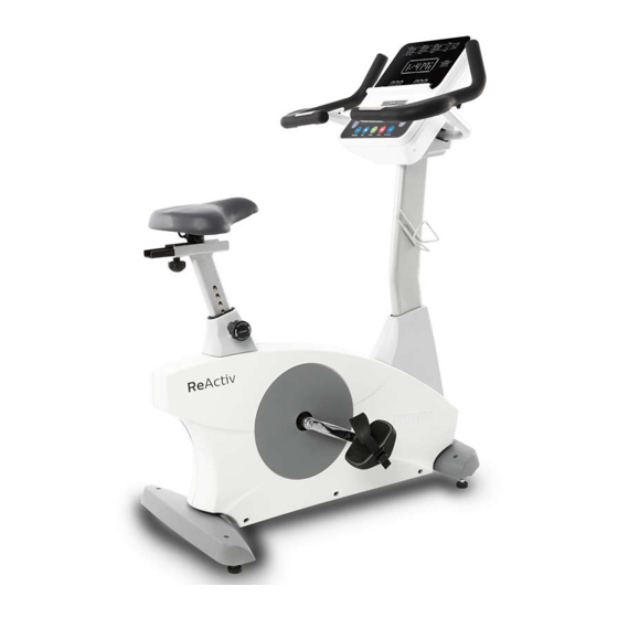
- Page 1 ReActiv User manual Upright bike Please read this entire manual carefully 4.0 U before operating your new upright bike and save it for future use. PTE4000CU Register your product and get support at www.philips.com/welcome...
- Page 2 Thank you for your recent purchase of the Philips physical rehabilitation upright bike 4.0 U. Philips physical therapy and exercise solutions provide simple, reliable products that o er the most relevant feedback to caregivers and users to achieve best-in-class outcomes and empower individuals to build con dence in rebuilding and maintaining healthy lifestyles and keep in touch with their communities.
-
Page 3: Table Of Contents
Contents Important safety instructions Important electrical information Important operation instructions Features Assembly instructions Console operation Using a heart rate transmitter Maintenance... -
Page 4: Important Safety Instructions
Important safety instructions Attention Read all instructions in this manual before using this device. Warning • Before beginning exercise on this product, or any exercise program, consult a physician. This is especially important for persons over the age of 35 or persons with preexisting health conditions. •... - Page 5 • Heart rate monitoring systems may be inaccurate. Over exercising may result in serious injury or death. If you feel faint stop exercising immediately. • Wear proper shoes. High heels, dress shoes, sandals or bare feet are not suitable for use on your bike. Quality athletic shoes are recommended to avoid leg fatigue.
-
Page 6: Important Electrical Information
Important electrical information Warning • Be aware that the generator is producing A.C. power while the bike is being used. Do not service the bike while the generator is spinning; serious electric shock could occur. • Never expose this product to rain or moisture. This product is not designed for use outdoors, near a pool or spa, or in any other high humidity environment. -
Page 7: Important Operation Instructions
Important operation instructions • Never operate this product without reading and completely understanding the results of any operational change you request from the console. • Understand that changes in resistance do not occur immediately. Set your desired resistance level on the console and release the adjustment key. -
Page 8: Features
Features 4.0 U-Upright bike Parts and adjustments 1. Console 2. Hand pulse grips 3. Fore / aft seat adjustment 4. Vertical seat adjustment 5. Pedal 6. Leveling glides Optional parts (not shown) 2.1 Adjustable crank set... -
Page 9: Assembly Instructions
Assembly instructions Unpacking • Cut the straps, then along the dotted line on the bottom of the box; lift the box over the unit and unpack. • Locate the hardware package. The hardware is separated into four steps. Remove the tools rst. Remove the hardware for each step as needed to avoid confusion. - Page 10 Assembly Read each step’s instructions and study the drawing carefully to become familiar with all the parts and procedures before beginning each step. Step 1. • Install the rear stabilizer (5) onto the main frame (1) with the four hex head bolts (50) and four at washers (71).
- Page 11 Step 2. • Run the wiring harness (29) through the console mast (2) and console mast cover (38) and out the top. • Assemble console mast (2) to main frame (1) with 6 bolts (51) and 6 washers (72) on the both side screws, 1 bolt (51) and 1 curved washer (99) on the front screw.
- Page 12 Step 3. • Install the handlebars (3) to console mast (2) with 4 bolts (60), 4 lock washers (64), 8 washers (57), and 4 nuts (84). • Run the 2 hand pulse wires (26 & 28) into the hole in the handle bar mounting plate and out through the hole in the console plate.
- Page 13 Step 4. • Connect wiring harness (26 & 28 & 29) to console (34). Attach console (34) to console mast (2) using 4 screws (75). Be careful not to pinch any wires. • Attach console bracket cover (42) to handlebars (3) using 2 screws (74). •...
-
Page 14: Console Operation
Console operation 4.0 U Console Message window Dot matrix window Program keys Resistance level or adjustment up / down keys Function keys Power on The 4.0 U has a built-in generator for power and does not need to be plugged into an AC outlet. To power up the bike simply start to pedal, the console will turn on automatically. - Page 15 CSAFE feature Your console is equipped with a CSAFE feature. The power (POWER) port can be used for powering a remote controlled audio-visual system by connecting a cable from the remote to the power port at the back of the console. The Communication port (COMM) can be used to interact with software applications.
- Page 16 Basic information When you begin a program the dot matrix will display the workout pro le. The message window will initially be displaying distance, calories, pulse and time information. On the bottom left of the key pad is a key labeled display.
- Page 17 The program keys may be used to preview each program when in the idle mode. When you rst turn the console on you may press each program key to preview what the program pro le looks like. If you decide that you want to try a program, press the corresponding program key and then press the con rm key to select the program and enter into the data-setup mode.
- Page 18 Entering a program and changing settings When you enter a program (by pressing a program key, then con rm key) you have the option of modifying the settings. If you want to begin without entering new settings just press the start key. This will bypass the programming of data and take you directly to the start of the program.
- Page 19 Preset programs The bike has three di erent programs that have been designed for a variety of workout goals. These programs factory preset work level pro les for achieving di erent goals. The initial built-in level of di culty for each program is set to a relatively easy level. You may adjust the level of di culty (max level) for each program before beginning.
- Page 20 Hill The Hill program simulates going up and down a hill. The resistance in the pedals will steadily increase and then decrease during the program. Plateau The Plateau program provides a steady state exercise with warm up and cool down periods. Interval The Interval program takes you through high levels of intensity followed by periods of low intensity.
- Page 21 Custom program The custom program allows you to build and save a custom program. You can build your own custom program by following the instructions below. The custom program allows you to further personalize it by adding your facility name. •...
- Page 22 - Now the rst column will be blinking and you are asked to adjust the level for the rst segment of the workout. When you nish adjusting the rst segment, or if you don’t want to change, then press con rm to continue to the next segment. - The next segment will show the same level as the previously adjusted segment.
- Page 23 VO2 Test The VO2 program is based on the YMCA protocol and is a sub-maximal test that uses pre-determined, xed work levels that are determined based on the heart rate readings measured as the test progresses. The test will take anywhere between 6 to 15 minutes to complete, depending on the tness level of the user.
- Page 24 Workload chart for female or de-conditioned male 1st Stage 150 kgm/min HR<80 HR: 80-90 HR: 90-100 HR>100 Heart Rate 125W 100W 2nd Stage 750 kgm/min 600 kgm/min 450 kgm/min 300 kgm/min 150W 125W 100W 3rd Stage 900 kgm/min 750 kgm/min 600 kgm/min 450 kgm/min 175W...
- Page 25 Before the test • Make sure you are in good health; check with your physician before performing any exercise if you are over the age of 35 or persons with pre-existing health conditions. • Adjust the seat to the proper position so that when your leg is extended during pedaling there is a slight bend at the knee of about 5 degrees.
- Page 26 What the score means VO2max Chart for males and very t females 18-25 26-35 36-45 46-55 56-65 years years years years years years excellent >60 >56 >51 >45 >41 >37 good 52-60 49-56 43-51 39-45 36-41 33-37 above average 47-51 43-48 39-42 35-38 32-35 29-32 average 42-46 40-42 35-38 32-35...
- Page 27 Using 1 MET as the reference value, light activities burn up to 3 times as many calories as rest, moderate activities burn 3-6 times as many and vigorous exercise more than 6 times as much energy as rest. METs programming •...
- Page 28 Metabolic rate activity chart Physical activity Light intensity activities <3 sleeping watching television writing, desk wirk, typing walking, 1.7mph (2.7 km/h), level ground, strolling, very slow walking 2.5 mph (4 km/h) Moderate intensity activities 3 to 6 bicycling, stationary, 50 watts, very light e ort walking 3.0 mph (4.8 km/h) calisthenics, home exercise, light or moderate e ort, general walking 3.4 mph (5.5 km/h)
- Page 29 Heart rate program The old motto; “no pain, no gain” is a myth that has been overpowered by the bene ts of exercising comfortably. A great deal of this success has been promoted by the use of heart rate monitors. With the proper use of a heart rate monitor, many people nd that their usual choice of exercise intensity was either too high or too low and exercise is much more enjoyable by maintaining their heart rate...
- Page 30 If you enter your age during programming the console will perform this calculation automatically. Entering your age is used for the heart rate programs. After calculating your MHR you can decide upon which goal you would like to pursue. The two most popular reasons for, or goals, of exercise are cardiovascular tness (training for the heart and lungs) and weight control.
- Page 31 The rate of perceived exertion (RPE), also known as the Borg scale, was developed by Swedish physiologist G.A.V. Borg. This scale rates exercise intensity from 6 to 20 depending upon how you feel or the perception of your e ort. The scale is as follows: Rating perception of e ort 6 Minimal 7 Very, very light...
- Page 32 Heart rate program programing To start the HR program follow the instructions below and follow the directions in the message window. • Press the HR key to select the HR program (TA HR 65% / TA HR 80% / HR interval) and then press the con rm key to enter. •...
- Page 33 Heart rate auto pilot mode The HR auto pilot mode only works in Fitness programs (manual / hill / plateau / interval / custom). When you are exercising in a tness program and decide to just maintain the HR level you are at currently you can just press auto pilot and the console will automatically switch to HR control and will maintain your current HR.
-
Page 34: Using A Heart Rate Transmitter
Using a heart rate transmitter Note The chest strap transmitter is not a standard part, but is a separate purchase. Most transmitters that operate at Bluetooth or ANT+ will also work. How to wear your wireless chest strap transmitter? • Attach the transmitter to the elastic strap using the locking parts. •... - Page 35 • Sweat is the best conductor to measure very minute heart beat electrical signals. However, plain water can also be used to pre-wet the electrodes (2 black square areas on the reverse side of the belt and either side of transmitter). It’s also recommended that you wear the transmitter strap a few minutes before your work out.
- Page 36 Erratic operation Caution! Do not use this product for heart rate control unless a steady, solid actual heart rate value is being displayed. High, wild, random numbers being displayed indicate a problem. Areas to look at for interference, which may cause erratic heart rate •...
-
Page 37: Maintenance
Maintenance • Wipe down all areas in the sweat path with a damp cloth after each use to prevent rust. • Check the pedal to make sure they are tight (monthly). • If a squeak, thump, clicking or rough feeling develops the main cause is most likely one of two reasons: - The hardware was not su ciently tightened during assembly. - Page 38 • Key test - Will allow you to test all the keys to make sure they are functioning. Press all the keys one at a time. • Display test - Tests all the display functions by lighting each LED light sequentially.
- Page 39 Exploded view drawing...
- Page 40 4.0 U parts list Item Description Main frame Console mast 3(A) Seat handle bar (l) 3(B) Seat handle bar (r) 3(C) Rear folding end assembly Plate Rear stabilizer Seat slider Sliding seat mount Fix plate Idler wheel assembly Crank axle Chain cover bracket Drive belt Drive pulley...
- Page 41 Item Description 34~03 Book rack 34~04 Fan assembly 34~05 Interface board 34~06 Console display board 34~07 Resistance button w/cable 34~08 De ector fan grill 34~09 Bluetooth 34~10 Csafe w/board 34~11 Interface board 34~12 Faceplate label 34~13 Fan grill anchor 34~14 Wind duct 34~15 End cap...
- Page 42 Item Description 3 × 20m/m_tapping screw 3/8" × 2m/m_ at head socket bolt M8 × p1.25 × 65l_socket head cap bolt Ø5 × 16m/m_tapping screw Ø8 × ø19 × 2t_ at washer Ø3.5 × 16m/m_sheet metal screw Ø8 × 1.5t_split washer M8 ×...
- Page 43 Item Description 12/14m/m_wrench Ø5/16" × 16 × 1.0t_ at washer Knob adjustor 106~2 M4 × 5l_phillips head screw Slider sleeve Slide spacer Drink bottle holder 13/15m/m_wrench 5/16" × 2-1/4"_hex head bolt Rubber pad...
- Page 44 Product warranty Dyaco Commercial & Medical North America LLC (hereinafter “Dyaco”), the manufacturer of the Philips Commercial Series Physical Therapy Products (hereinafter “Products”) warrants all of the Products and their components listed below for the periods of time set out on this page below from the date of sale, as determined by sale receipt, or in the absence of a sales receipt, eighteen (18) months from the original factory shipping date.
- Page 45 • Proper connection to a grounded power supply of su cient voltage, replacement of blown fuses, repair of loose connections or defects in house or facility wiring. • Expenses for making the tness equipment accessible for servicing, including any item that was not part of the tness equipment at the time it was shipped from the factory.
- Page 46 • Manufacturer, distributor, or the Licensor shall not be responsible or liable of any direct, indirect, general, special, punitive, incidental or consequential damages; loss of or damage to property; claims of third parties; loss of life; personal injury (including further injury, or re-injury), and any other losses or damages of any kind or character, arising out of or in connection with the use of Biophysical Agents by the facilities or clinicians.
- Page 47 Service Keep your bill of sale. Twenty four (24) months from the date on the bill of sale or eighteen (18) months from the date of factory shipping as determined by the serial number establishes the warranty period should service be required. If service is performed, it is in your best interest to obtain and keep all receipts.
- Page 48 2019© Dyaco Commercial & Medical North America LLC. All right reserved. Philips and the Philips Shield Emblem are registered trademarks of Koninklijke Philips N.V. and are used under license. This product has been manufactured by and is sold under the responsibility of Dyaco Commercial & Medical North America LLC,...