Table of Contents
Quick Links
DISMANTLING INSTRUCTIONS............................................2
BLOCK DIAGRAM...................................................................3
WIRING DIAGRAM.................................................................4
CIRCUIT DIAGRAM MAIN BOARD.......................................5-7
CIRCUIT DIAGRAM PANEL BOARD......................................8
CIRCUIT DIAGRAM TUNER BOARD.......................................9
2012-6-15
MAIN PCB COMPONENT LAYOUT.........................................10-11
PANEL PCB COMPONENT LAYOUT.......................................12-13
TUNER PCB COMPONENT LAYOUT........................................14-15
CD CONNECTOR PCB COMPONENT LAYOUT.......................16
ISO PCB COMPONENT LAYOUT..............................................17
SET EXPLODER VIEW DRAWING.............................................18
TROUBLE SHOOTING................................................................19-20
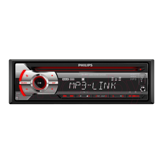
CEM2101R/51
Table of Contents

Summary of Contents for Philips CEM2101R/51
-
Page 1: Table Of Contents
CEM2101R/51 MAIN PCB COMPONENT LAYOUT.........10-11 DISMANTLING INSTRUCTIONS..........2 PANEL PCB COMPONENT LAYOUT........12-13 BLOCK DIAGRAM..............3 TUNER PCB COMPONENT LAYOUT........14-15 WIRING DIAGRAM..............4 CD CONNECTOR PCB COMPONENT LAYOUT.......16 CIRCUIT DIAGRAM MAIN BOARD........5-7 ISO PCB COMPONENT LAYOUT..........17 CIRCUIT DIAGRAM PANEL BOARD........8 SET EXPLODER VIEW DRAWING..........18 CIRCUIT DIAGRAM TUNER BOARD........9... -
Page 2: Dismantling Instructions
The procedure of disassembling the unit 1.Press EJ button and take out panel remove A screw in top cover of the unit; Use tweezer to prize up top cover as the blue arrow direction which showed as below picture 2) Remove B,C screws in left and right side of metal bracket; Then remove D,E screws in panel base;Remove deck mechanism The procedure of disassembling the panel... -
Page 4: Wiring Diagram
WIRING DIAGRAM... -
Page 5: Circuit Diagram Main Board
CIRCUIT DIAGRAM -MAIN BOARD... -
Page 8: Circuit Diagram Panel Board
CIRCUIT DIAGRAM -PANEL BOARD... -
Page 9: Circuit Diagram Tuner Board
CIRCUIT DIAGRAM -TUNER BOARD XT001 R014 C009 32.768KHz C008 R001 270K C001 L001 C004 Q001 C006 C003 R003 220NH L003 RFGND L002 C002 SK255 2.7UH 220NH IC001 LOUT R002 C005 CTUNE SI474X ROUT RF-GND L006 C017 33UH Q102/Q003 L004 L005 C013 C025 C007... -
Page 10: Main Pcb Component Layout
PCB LAYOUT -MAIN BOARD TOP SIDE VIEW... - Page 11 PCB LAYOUT -MAIN BOARD BOTTOM SIDE VIEW...
-
Page 12: Panel Pcb Component Layout
PCB LAYOUT -PANEL BOARD TOP SIDE VIEW... - Page 13 PCB LAYOUT -PANEL BOARD BOTTOM SIDE VIEW...
-
Page 14: Tuner Pcb Component Layout
PCB LAYOUT -TUNER BOARD TOP SIDE VIEW... - Page 15 PCB LAYOUT -TUNER BOARD BOTTOM SIDE VIEW...
-
Page 16: Cd Connector Pcb Component Layout
PCB LAYOUT CD CONNECTOR TOP SIDE VIEW... -
Page 17: Iso Pcb Component Layout
PCB LAYOUT-ISO BOARD BOTTOM SIDE VIEW... -
Page 18: Set Exploder View Drawing
SET EXPLODER VIEW DRAING... -
Page 19: Trouble Shooting
Product Area Date 2012-6-20 CEM2101 Model failure failure cause remark phenomena a. To check whether it is connect well of the ISO connector (4PIN power input ). Whether it is loose of the 15A fuse of the ISO connector, or insert non in place. b. - Page 20 failure failure cause remark a. To check whether the signal format of the disc is correspond to the request of the unit, whether there is any contamination or damage or light leakage on the surface of the disc. b. To check whether there is any abnormal of the rotation of the deck mecahnism, or whether the disc is enter in position.


