Table of Contents
Quick Links
WM-FX651/FX653/FX655
SERVICE MANUAL
Ver 1.1 2002. 01
Sony Corporation
9-923-157-12
2002A1600-1
Personal Audio Company
© 2002.1
Published by Sony Engineering Corporation
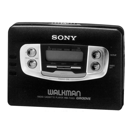
Photo : WM-FX651
RADIO CASSETTE PLAYER
AEP Model
WM-FX651/FX653/FX655
E Model
WM-FX653/FX655
Australian Model
Tourist Model
WM-FX655
Canadian Model
WN-FX653
Table of Contents

Summary of Contents for Sony WM-FX651
- Page 1 SERVICE MANUAL AEP Model WM-FX651/FX653/FX655 Ver 1.1 2002. 01 E Model WM-FX653/FX655 Australian Model Tourist Model WM-FX655 Canadian Model WN-FX653 Photo : WM-FX651 RADIO CASSETTE PLAYER Sony Corporation 9-923-157-12 2002A1600-1 Personal Audio Company © 2002.1 Published by Sony Engineering Corporation...
-
Page 2: Table Of Contents
TABLE OF CONTENTS Specification ················································································· 1 1. GENERAL ·········································································· 3 2. SERVICE NOTE ······························································· 3 3. DISASSEMBLY 3-1. Case Assy Removal ······················································· 4 3-2. Tuner Board Removal ··················································· 4 3-3. Audio Board Removal ··················································· 5 3-4. Cassette Lid Assy Removal ··········································· 5 3-5. -
Page 3: General
SECTION 1 GENERAL • LOCATION OF CONTROL 1 OPEN knob 2 PRESET + /AMS FF button 3 PRESET – /AMS REW button 4 TUNING + button !¢ 5 TUNING – button 6 ENTER button 7 ˇ /REPEAT button 8 p /RADIO OFF button 9 MENU button 0 SET button !“... -
Page 4: Disassembly
SECTION 3 DISASSEMBLY Note : Follow the disassembly procedure in the numerical order given. 3-1. CASE ASSY REMOVAL 3 Screw (M1.4 × 2.2) 5 Case assy 2 Screw 1 Screw (M1.4 × 2.2) (M1.4 × 2.2) 3-2. TUNER BOARD REMOVAL 1 Scew (M1.7 ×... -
Page 5: Audio Board Removal
3-3. AUDIO BOARD REMOVAL 7 AUDIO board 2 Remove solder 1 Screw (M1.7 × 3) 4 Flexible board 3 Remove solder 3-4. CASSETTE LID ASSY REMOVAL 2 Screw (M1.4 × 2) 5 Cassette lid assy 3 Screw (M1.4 × 2) 1 OPEN button —... -
Page 6: Mechanism Deck Removal
3-5. MECHANISM DECK REMOVAL 4 Reel ornament 5 Mechanism deck — 6 —... - Page 7 SECTION 4 SECTION 5 SECTION 6 MECHANICAL ADJUSTMENT ELECTRICAL ADJUSTMENT EXPLANATION OF IC TERMINALS PRECAUTION PRECAUTION TUNER SECTION FM VCO Adjustment • IC1 TC9326F Clean the following parts with a denatured-alcahol-moistened Specified voltage : 1.3V Procedure : Pin No. Function Pin Name Circuit Description...
-
Page 12: Diagrams
MEMO • IC BLOCK DIAGRAMS IC3 TA7371AF-EL (TUNER SECTION) IC301 TA2072AF (AUDIO SECTION) IC601 MM1279XVBE (AUDIO SECTION) IC7 TA-2022AFN-EL (TUNER SECTION) — 25 — — 26 —... -
Page 13: Exploded Views
SECTION 8 EXPLODED VIEWS NOTE: • -XX, -X mean standardized parts, so they may • The mechanical parts with no reference number • Abbreviation have some differences from the original one. in the exploded views are not supplied. CND : Canadian model •... -
Page 14: Audio, Tuner Board Section
8-2. AUDIO, TUNER BOARD SECTION S901 MT-WMEX550-125 Ref. No. Part No. Description Remarks Ref. No. Part No. Description Remarks 3-375-114-11 SCREW (M1.7X3.5) X-3373-589-1 BRACKET ASSY (FX651/FX653:CND,E,EA,KR,FX655) 3-009-667-01 SPRING, TENSION 3-375-114-41 SCREW (M1.7X3) 3-937-993-41 LID, BATTERY CASE A-3016-925-A TUNER BOARD, COMPLETE X-3373-190-1 TERMINAL BOARD ASSY, BATTERY A-3061-468-A AUDIO BOARD, COMPLETE 3-009-690-01 TERMINAL BOARD, BATTERY... -
Page 15: Mechanism Section (Mt-Wmex550-125)
8-3. MECHANISM SECTION (MT-WMEX550-125) PM901 M901 HP301 not supplied Ref. No. Part No. Description Remarks Ref. No. Part No. Description Remarks 3-011-277-01 COVER (B) (Y), MD X-3373-245-1 CHASSIS (S) ASSY (Y) 3-704-413-31 SCREW (M1.4X7.2) 3-007-455-01 SPRING (R), TORSION X-3372-850-1 PINCH LEVER (N) ASSY 3-007-458-01 SPRING (H/B), TENSION 3-007-434-01 PULLEY (REVERSE) 3-007-456-01 SPRING (N), TORSION... -
Page 16: Electrical Parts List
SECTION 9 AUDIO ELECTRICAL PARTS LIST NOTE: • Due to standardization, replacements in the • RESISTORS When indicating parts by reference number, parts list may be different from the parts All resistors are in ohms. please include the board naame. specified in the diagrams or the components METAL: metal-film resistor The components identified by mark ! or... - Page 17 AUDIO TUNER Ref. No. Part No. Description Remarks Ref. No. Part No. Description Remarks < COIL > R303 1-216-825-11 METAL CHIP 2.2K 1/16W R304 1-218-295-11 METAL GLAZE 1/16W L101 1-412-011-31 INDUCTOR CHIP 27uH R305 1-216-821-11 METAL CHIP 1/16W L201 1-412-011-31 INDUCTOR CHIP 27uH R307 1-216-847-11 METAL CHIP 150K...
- Page 18 Ver 1.1 2002.01 TUNER Ref. No. Part No. Description Remarks Ref. No. Part No. Description Remarks 1-162-917-11 CERAMIC CHIP 15PF 1-135-091-00 TANTALUM CHIP 1uF 1-162-917-11 CERAMIC CHIP 15PF 1-162-964-11 CERAMIC CHIP 0.001uF 1-162-970-11 CERAMIC CHIP 0.01uF 1-162-964-11 CERAMIC CHIP 0.001uF 1-162-964-11 CERAMIC CHIP 0.001uF 1-162-964-11 CERAMIC CHIP...
- Page 19 TUNER Ref. No. Part No. Description Remarks Ref. No. Part No. Description Remarks < LIQUID CRYSTAL DISPLAY > 1-218-849-11 METAL GLAZE 1.2K 0.50% 1/16W 1-218-851-11 METAL GLAZE 1.5K 0.50% 1/16W 1-801-656-11 DISPLAY PANEL, LIQUID CRYSTAL 1-218-863-11 METAL GLAZE 4.7K 0.50% 1/16W 1-218-859-11 METAL GLAZE 3.3K 0.50% 1/16W...
- Page 20 WM-FX651/FX653/FX655 TUNER Ref. No. Part No. Description Remarks Ref. No. Part No. Description Remarks 1-771-053-11 SWITCH, KEY BOARD (MENU) ACCESSORIES & PACKING MATERIALS 1-771-053-11 SWITCH, KEY BOARD (SET) ******************************* 1-692-453-11 SWITCH, KEY BOARD (TUNING +) 1-692-453-11 SWITCH, KEY BOARD (TUNING -)
- Page 21 WM-FX651/FX653/FX655 AEP Model WM-FX651/FX653/FX655 E Model SERVICE MANUAL WM-FX653/FX655 Australian Model Tourist Model WM-FX655 Canadian Model WM-FX653 SUPPLEMENT-1 File this supplement with the Service Manual. Subject : Change Notice of the TUNER Board Suffix from -11 to -12. (Deletion of the RESET Board) and...
- Page 22 SERVICE NOTE • Regarding the method of adjustment and voltage check, perform sections 3-1 and 3-2 of the DISASSEMBLY, and attach the JIG to the AUDIO board as shown below. Screw Screw (M1.4 × 5.0) (M1.4 × 5.0) TUNER board J-2503-005-A Screw (M1.7 ×...
- Page 23 WM-FX651/FX653/FX655 CORRECTION : Indicates corrected portion 8-1. CABINET SECTION 8-2. AUDIO, TUNER BOARD SECTION • Addition of Chainese model. • Change notice of the TUNER board. Exploded views CN: Chinese model ELECTRICAL PARTS LIST Page • TUNER BOARD Ref. No.
- Page 26 WM-FX651/FX653/FX655 — 14 — — 16 — — 15 —...
- Page 27 WM-FX651/FX653/FX655 Printing Method for Large Sized Documents Such As Circuit Diagrams Printing the page that exceeds A4-size two pages (or letter size) is possible by specifying the print range. (Acrobat Reader Version 4.0 or later) 1. The enlarged print is made, if a smaller range than A4 size is specified and the A4 size is selected as a print paper.
- Page 28 WM-FX651/FX653/FX655 REVISION HISTORY Clicking the version allows you to jump to the revised page. Also, clicking the version at the upper right on the revised page allows you to jump to the next revised page. Ver. Date Description of Revision 1997.03...