
Related Manuals for Panasonic AJ-SD965E

Summary of Contents for Panasonic AJ-SD965E
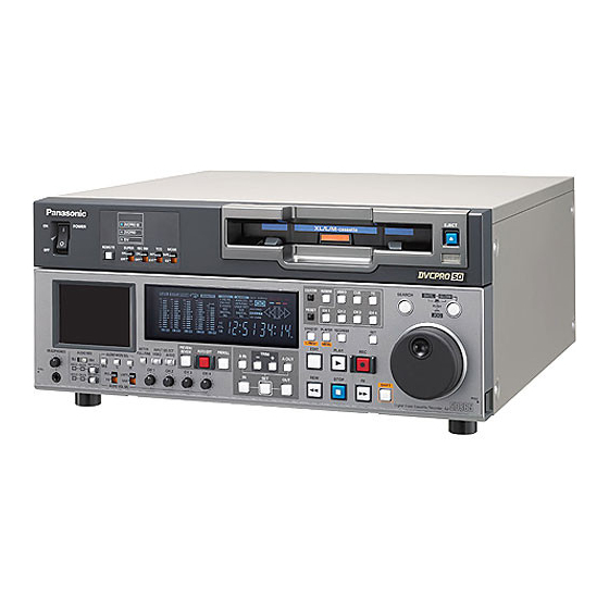
- Page 1 Operating Instructions Digital Video Cassette Recorder Model No. Before operating this product, please read the instructions carefully and save this manual for future use. ENGLISH F1104W0 -F @ Printed in Japan VQT0N88...
- Page 2 If you lose the fuse cover the plug must not be used until a replacement cover is obtained. A replacement fuse cover can be purchased from your Fuse local Panasonic Dealer. indicates safety information. 2 (E)
- Page 3 IMPORTANT “Unauthorized recording of copyrighted television programmes, video tapes and other materials may infringe the right of copyright owners and be contrary to copyright laws.” Operating precaution Operation near any appliance which generates strong magnetic fields may give rise to noise in the video and audio signals.
-
Page 4: Table Of Contents
Contents Introduction ....... .4 Time code/user bit ......62 Features . -
Page 5: Features
A cassette adapter (AJ-CS455P) is necessary when a mini DV cassette tape is to be used. Digital slow motion/jog dial Panasonic’s original digital slow-motion technology makes it possible to attain clear pictures even during slow playback at speeds of –0.43 to +0.43/+0.5/+0.75. - Page 6 Features (continued) Multifunctional interface O Serial digital input/output A component serial interface is provided as standard and enables interfacing of the serial digital component signals. O Analog video input/output Both composite and component signal outputs are provided as standard. Use of an analog video input board (AJ-YA932G, optional accessory) enables interfacing of the component (Y, PB, PR) and composite signal input.
-
Page 7: Parts And Their Functions
Parts and their functions Front panel 5 REC INH switch This switch is used to enable or disable recording on the cassette tape. EJECT DVCPRO 50 XL/L/M-cassette POWER DVCPRO SUPER REC INH MODE REMOTE TAPE Recording on the cassette tape is disabled SHTL SLOW COUNTER... - Page 8 Parts and their functions (continued) Front panel = FF button MODE switch When this button is pressed, the tape is fast forwarded. EJECT DVCPRO 50 XL/L/M-cassette POWER DVCPRO The fast forwarding speed can be selected using REMOTE SUPER REC INH MODE TAPE setup menu No.102 (FF.
- Page 9 Parts and their functions (continued) Front panel D Search dial This dial is used to locate the edit points. Each time it is pressed, it is set alternatively to the SHTL/SLOW mode or the JOG mode, and the JOG, EJECT DVCPRO 50 XL/L/M-cassette POWER...
- Page 10 Parts and their functions (continued) Front panel L PREROLL button This button is used to locate where a transmission EJECT or manual editing starts on the tape. DVCPRO 50 XL/L/M-cassette POWER DVCPRO When it is pressed, the tape travels to the preroll SUPER REC INH MODE REMOTE...
- Page 11 Parts and their functions (continued) Front panel R INPUT SELECT buttons These buttons switch the video and audio input signals. It is also possible to switch the input signals EJECT DVCPRO 50 to the internal reference signal selected on setup XL/L/M-cassette POWER DVCPRO...
- Page 12 Parts and their functions (continued) Front panel REC CH1/CH3 and REC CH2/CH4 buttons, and CH1/3 and CH2/4 lamps These buttons are used to switch the input signals EJECT DVCPRO 50 XL/L/M-cassette POWER DVCPRO to be recorded on the CH1, CH2, CH3 and CH4 SUPER REC INH MODE REMOTE...
- Page 13 Parts and their functions (continued) Front panel X AUDIO VOL SEL (REC/PB) switch This switches the function of the audio level control knobs W between recording and playback. EJECT DVCPRO 50 XL/L/M-cassette POWER REC: DVCPRO SUPER REC INH MODE REMOTE TAPE Adjustment of recording level SHTL...
- Page 14 Parts and their functions (continued) Front panel SET UP (BLK) control and switch EJECT DVCPRO 50 These are used to adjust the setup (black) level. XL/L/M-cassette POWER DVCPRO SUPER REC INH MODE REMOTE TAPE When the ENC CONTROL switch is set to LOCAL and the SET UP switch is set to MANUAL, SHTL SLOW...
- Page 15 Parts and their functions (continued) Front panel EJECT DVCPRO 50 XL/L/M-cassette POWER DVCPRO SUPER REC INH MODE REMOTE TAPE SHIFT SHTL SLOW COUNTER ASSEM VIDEO SEARCH PUSH INSERT RESET CH 1 CH 2 CH 3 CH 4 PF 1 PF 2 PF 3 PF 4 STAND BY...
-
Page 16: Display Panel
Parts and their functions (continued) Display panel SERVO WIDE REMOTE VIDEO AUDIO Y PB PR ANALOG EDIT REC CMPST AES/EBU USER SET DVCPRO SDTI/1394 SDTI/1394 DVCAM SG 1 2 1 TV system displays lamp The selected TV system is displayed here. This lamp lights when UMID information is present It is possible to switch between the 525 interlace on the input signal in E-E mode. - Page 17 Parts and their functions (continued) Display panel SERVO WIDE REMOTE VIDEO AUDIO Y PB PR ANALOG EDIT REC CMPST AES/EBU USER SET DVCPRO SDTI/1394 SDTI/1394 DVCAM SG 1 2 < > : EDIT, EDIT REC, REC and REC INH lamps = Counter display EDIT: The tape counter, time code, etc.
-
Page 18: Rear Panel
Parts and their functions (continued) Rear panel 6 Remote control connectors These connectors make it possible to use two of AES/EBU ANALOG REMOTE ANALOG these VTRs or to connect this VTR to an external CH1/2 VIDEO AC IN REMOTE IN/OUT PUSH PUSH PUSH... - Page 19 Parts and their functions (continued) Rear panel A PARALLEL REMOTE connector AES/EBU ANALOG REMOTE ANALOG CH1/2 VIDEO AC IN This connector is used when the VTR is to be REMOTE IN/OUT PUSH PUSH PUSH AUDIO 75Ω CH3/4 REMOTE operated by an external component. ACTIVE PUSH PUSH...
-
Page 20: Connections
Connections Source machine: Set the REMOTE button 3 on the front panel to the remote mode (REMOTE lamp ON). Recorder: Set the REMOTE button 3 on the front panel to the local mode (REMOTE lamp OFF). Reference signal generator Remote control signal (9 pin) Digital video/audio signal Source machine Recorder... - Page 21 Connections (continued) Connections with editing controller Recorder AV monitor Video monitor EJECT DVCPRO 50 XL/L/M-cassette POWER signals DVCPRO SUPER REC INH MODE REMOTE TAPE SHTL SLOW COUNTER ASSEM VIDEO SEARCH PUSH INSERT RESET CH 1 CH 2 CH 3 CH 4 PF 1 PF 2 PF 3...
-
Page 22: Tapes
It is recommended that tapes bearing the The cassette tape will load automatically. Panasonic brand be used as the consumer-use DV tapes. M cassettes Tapes enabling recording and playback for up to 33 minutes at the 50 Mbps rate and for up to 66 minutes at the 25 Mbps rate. -
Page 23: Jog/Shuttle
Jog/Shuttle Jog mode Shuttle mode Press the search dial so that it remains pressed in. Press the search dial so that it is released from the Check that the JOG lamp has lit. pressed-in position. The SHTL lamp lights, and the shuttle mode is established. -
Page 24: Manual Editing
Manual editing Select the editing mode. While monitoring the TV monitor, search the ASSEMBLE: position (IN point) where the editing is to be started, Assemble (frame-to-frame continuity) editing is and press the PLAY and EDIT buttons together at performed in this mode. this position. -
Page 25: Automatic Editing (Deck-To-Deck)
Automatic editing (deck-to-deck) Switch settings and adjustments When using the AJ-SD965 as the recorder When using the AJ-SD965 as the player Set the POWER switch to ON. Set the POWER switch to ON. Use the INPUT SELECT buttons to select the video Set the AUDIO VOL SEL (REC/PB) switch to the and audio input signals. -
Page 26: Selecting The Editing Mode
Automatic editing (deck-to-deck) (continued) Selecting the editing mode Registering the edit points Select the editing mode. Locate the edit IN point by performing the jog or For assemble editing, press the ASSEM button. shuttle operation. For insert editing, press the INSERT button. Set the tape to the still picture mode at the desired ASSEM: position. -
Page 27: Checking And Previewing Edit Points
Automatic editing (deck-to-deck) (continued) Checking and previewing edit points Press the IN (or OUT) button to check the edit EJECT point. The value of the registered edit point appears DVCPRO 50 XL/L/M-cassette POWER DVCPRO on the display panel. SUPER REC INH MODE REMOTE TAPE... -
Page 28: Modifying Edit Points
Automatic editing (deck-to-deck) (continued) Modifying edit points Re-registering an edit point Locate the new edit point by performing the jog or shuttle operation, and press the IN (or OUT) button and SET button at the same time to re-register the edit point. -
Page 29: Executing And Reviewing Automatic Editing
Automatic editing (deck-to-deck) (continued) Executing and reviewing automatic editing Press the AUTO EDIT button. Upon completion of the editing, press the REVIEW Automatic editing is now executed. button. O To suspend editing at any time, press the STOP Review is then started by the recorder side. button. -
Page 30: Audio Split Editing
Audio split editing The video edit points and audio edit points can be EJECT registered independently, and editing can be executed DVCPRO 50 XL/L/M-cassette POWER DVCPRO SUPER REC INH MODE REMOTE with the video point offset from the audio points. TAPE Audio edit points cannot be registered when the SHTL... - Page 31 Audio split editing (continued) $ Duration display The duration can be indicated on the display panel only. Between the video IN and OUT points: Press the IN button and OUT button at the same time. Between the audio IN and OUT points: Press the A IN button and A OUT button at the same time.
-
Page 32: Variable Memory Editing
Variable memory editing Using the unit as a controller (deck-to-deck editing After selecting VTR used as the player by pressing mode recorder) to control the playback speed of the PLAYER button, set the initial speed by the search VTR used as the player, editing can be performed in dial while pressing SET button. -
Page 33: Pf (Programmable Function) Functions
PF (Programmable Function) functions Four most frequently used setup items can be Turn the search dial to move the cursor (2) to the registered in the four PF buttons. item to be registered. Registering setup items in the PF Press the STOP button. buttons The display screen returns to the status in step and the registered item is displayed at the position... -
Page 34: Setup (Initial Settings)
Setup (initial settings) This VTR’s main settings are performed while making At the position where the change is to be made, selections using a system of menus. turn the search dial while holding down the search button. FF button The settings on the menu screen and display now flash. -
Page 35: Setup Menus
Setup menus This VTR can hold five user files, each of which has its Setting and releasing the lock mode own specific menu settings, and one of these files can be selected for use. The lock mode can be set to protect the system file and user file (USER2 to USER5) settings. - Page 36 Setup menus (continued) Loading user files The contents of the USER2, USER3, USER4 or Press the SET button. USER5 file can be copied (loaded) into the USER1 file. The following message appears on the menu Also, the contents of the USER1 file can be copied screen and counter display.
- Page 37 Setup menus (continued) Saving user files Press the (SHIFT+RECORDER). Press the PLAY button. MENU The settings of USER1 are saved in the user file selected in step and stored in the memory. If the Press the REW button or FF button while holding STOP button is pressed instead, the settings are down the SHIFT button to select the USER1 file.
-
Page 38: System Menu
Setup menus (continued) SYSTEM menu No./Item Description No./Item Description This selects the signal to output from the SCH phase adjustment: 90° units VIDEO OUT 2 connector. (The SC phase changes but the H phase does WFM SEL SCH COARSE not change.) 0000 CTL : The CTL signal is output. - Page 39 Setup menus (continued) SYSTEM menu No./Item Description No./Item Description System phase adjustment. This adjusts the brightness of the LCD monitor on the front panel. SYS H OFFSET 0000 –3 : –13.4 µsec BRIGHT 0001 –2 : –8.96 µsec 0000 –7 0002 –1 : –4.52 µsec 0003...
-
Page 40: User Menus
Setup menus (continued) USER menuNo./Item Description No./Item Description This sets the preroll time. This selects whether or not to synchronize The preroll time can be set from 0 to 15 seconds between two VTRs. P-ROLL TIME in 1-second increments. SYNCHRONIZE 0000 OFF :... -
Page 41
Setup menus (continued) USER menu
No./Item Description No./Item Description This sets the position of the characters on This sets the format in which the tape is to the horizontal plane for the time code and be played back. CHARA H-POS other super displays output to the VIDEO PB FORMAT OUT 3/SDI OUT 3 connector. -
Page 42: Operation
Setup menus (continued) USER menuNo./Item Description No./Item Description This selects the direct search dial operation. This selects the VTR mode in which the EE status is established when the MODE switch SEARCH ENA 0000 DIAL : AUTO EE SEL is set to EE. -
Page 43
Setup menus (continued) USER menu
No./Item Description No./Item Description This selects whether to rewind the tape This selects the output picture in the automatically to the tape start when the tape STANDBY OFF (HALF LOADING) and EJECT AUTO REW end is detected. -
Page 44
Setup menus (continued) USER menu
No./Item Description This selects whether to cause the REC INH lamp to flash or light up when the cassette REC INH LAMP has been set to the accidental erasure prevention status. 0000 LIGHT : The lamp lights up. 0001 FLASH : The lamp flashes. -
Page 45: Interface
DVCPRO’s is set in OTHER. STANDBY ON or STANDBY OFF mode is OThe ORIG setting should only be used when a selected alternately. Panasonic controller (AG-A850 etc. sold 0001 ON : separately) is connected. When active signals are detected in the... -
Page 46: Edit
Setup menus (continued) USER menuNo./Item Description No./Item Description This sets the channel assignments for the This selects the operation to be performed controller’s analog audio preset when editing when an edit point has been set incorrectly EDIT RPLCE1 the digital audio of the VTR using a controller IN/OUT DEL (when the OUT point is before the IN point). -
Page 47
Setup menus (continued) USER menu
No./Item Description No./Item Description The same type of setting as setup menu No. This selects the CF adjustment deck with 305. This selects the channel concerned deck-to-deck editing. EDIT RPLCE4 when the CH4 edit preset is set in CF ADJ SEL compliance with the ON or OFF presetting for 0000 PLAYER :... -
Page 48: Tape Protect
Setup menus (continued) USER menuNo./Item Description No./Item Description This sets the maximum JOG REV speed. When the time selected as the setup menu item No. 400 (STILL TIMER) setting elapses JOG REV MAX 0000 –4.1 : –4.1 (–3.1)a speed SRC PROTECT while the unit is in the search STILL 0001... -
Page 49: Time Code
Setup menus (continued) USER menu - Page 50 Setup menus (continued) USER menu
-
Page 51: Video
Setup menus (continued) USER menu - Page 52 Setup menus (continued) USER menu
- Page 53 Setup menus (continued) USER menu
- Page 54 Setup menus (continued) USER menu
-
Page 55: Audio
Setup menus (continued) USER menu - Page 56 Setup menus (continued) USER menu
- Page 57 Setup menus (continued) USER menu
-
Page 58: Blank
Setup menus (continued) USER menuNo./Item Description No./Item Description For selecting the mode for recording signals Sub-screen on additional lines. For selecting the additional line where the ADD LINE 25 REC LINE2 signals are to be recorded. 0000 OFF : No signals are recorded on additional lines. -
Page 59
Setup menus (continued) USER menu
No./Item Description No./Item Description For selecting the mode for recording signals Sub-screen on additional lines. For selecting the additional line where the ADD LINE 50 REC LINE3 signals are to be recorded. 0000 OFF : No signals are recorded on additional lines. -
Page 60
Setup menus (continued) USER menu
No./Item Description No./Item Description For selecting the method used to detect the This turns the blanking ON or OFF in the lines in which the teletext signals are to be vertical blanking period of the video output TELETEXT recorded. -
Page 61: Lcd
Setup menus (continued) USER menuNo./Item Description No./Item Description This sets the LCD monitor’s saving function This loads the contents of the selected user (see page 11). file into USER1 and it starts operation with LCD PROTECT P. ON LOAD the USER1 settings when the power is turned 0000 OFF :... -
Page 62: Time Code/User Bit
Time code/user bit Time code Use the TC (REC RUN/FREE RUN) switch to set the operation mode in which the internal time code The time code is used when the time code signal generator is to be advanced. generated by the time code generator (time code REC RUN: signal generator) is to be recorded on the tape, its The internal time code generator is advanced... - Page 63 Time code/user bit (continued) Setting the external time code Reproducing the time code/user bit Set the VTR to stop mode. Set the VTR to stop mode. Select “TC” using the COUNTER button. Select “TC” or “UB” using the COUNTER button. Set the TCG switch to EXT.
-
Page 64: Superimpose Screen
Superimpose screen The control signals, time code, etc. are displayed using Characters displayed abbreviations. The background of characters superimposed on the display can be changed using setup menu No. 011 (CHARA TYPE). TV monitor TCR 22 : 22 : 22 : 22 TCR 22 : 22 : 22 : 22 T T C C R R 2 2 2 2 : : 2 2 2 2 : : 2 2 2 2 : : 2 2 2 2 Abbreviations:... -
Page 65: Video Output Signals And Servo Reference
Video output signals and servo reference signal This section explains how the output signals and servoreference signal are selected. Synchronization is determined as follows depending on the availability of the REF VIDEO input signal when “BB”, “CB100” or “CB75” has been selected as the External synchronization of video setup menu No. -
Page 66
Video output signals and servo reference signal (continued) Servo reference signal
Synchronization is determined as follows depending on the availability of the REF VIDEO input signal when The REF VIDEO input signal or video input signal is “BB”, “CB100” or “CB75” has been selected as the selected as the servo reference signal. -
Page 67: Audio V Fade Function
Audio V fade function When editing tapes, the edit point splicing selection (setup menu No. 311 and 312) information is recorded on the tape. This information is then sensed during playback, and V fade or cut processing is automatically performed for these sections. However, only when the playback fade selection (No. -
Page 68: Audio Recording Channel And Monitor Output
Audio recording channel and monitor output selection Audio recording channel Monitor output channel The audio recording channels are selected on the The monitor output channels are selected using the AUDIO setup menu as shown below. AUDIO MON SEL (L and R) and AUDIO MON SEL (MIX) buttons as shown below. -
Page 69: Rack Mounting
457.2 mm (18-inch) rail and bracket (model number CC3061-99-0400) by Chassis Trak be used. (The complete slide rail and bracket unit is not available from Panasonic.) For further details, consult your dealer. Attach the inner members of the slide rails. -
Page 70: Video Head Cleaning
Video head cleaning This unit is equipped with an auto head cleaning For further details on how to actually clean the heads, function which automatically reduces the amount of dirt consult with one of our service companies or with your on the video heads. -
Page 71: Error Messages
Error messages When a warning occurs in this unit, the error number is $ “WARNING” information display indicated on the counter display. O A warning message is displayed whenever a Open the DIAG menu to display a description of the warning occurs. - Page 72 Error messages (continued) If “T&S&M” is selected in the setup menu No. 008 $ Displaying the “HOURS METER” (DISPLAY SEL), a message appears in the mode information display whenever a warning or error occurs. When Turn the search dial to move the cursor (2). multiple events occur, the event with the highest The description for the item where the cursor is located priority is displayed.
- Page 73 Error messages (continued) Warning messages OMonitor display OMonitor display Priority Priority ODescription ODescription OVTR operation and corrective action OVTR operation and corrective action High E-04 (UNKNOWN SIG) E-09 (NO RF) This appears when the SDTI input signals are not This appears during playback when a blank section DVCPRO or DV format signals.
- Page 74 Error messages (continued) Error messages ODescription ODescription Display Display OVTR operation and corrective action OVTR operation and corrective action E-20 If condensation is detected, the error number E-51 If the take-up reel rotates without engaging for a flashes and the unit transfers to eject mode. The specific period of time during the start or end drum rotates after the cassette is ejected to FRONT LOAD...
- Page 75 Error messages (continued) Error messages Consult your dealer if the error message is still ODescription Display OVTR operation and corrective action displayed even after restarting the unit. E-64 If the supply reel motor speed is abnormally high, the error number flashes on the display. S REEL ROTA VTR: STOP TOO FAST...
-
Page 76: Rs-232C Interface
RS-232C interface The VTR can be operated by commands when the RS- Hardware specifications 232C interface is used. (See command table on pages 79, 80.) External interface specifications $ Conditions for acknowledging O Connector specifications commands from RS-232C interface Connector: O The REMOTE button on the front panel must be D-SUB 25-pin (crossover cable supported) set to the remote mode (REMOTE lamp ON). -
Page 77
RS-232C interface (continued) Software specifications (Protocol) 2. Send format [controller (PC) 5 VTR] 1. Communication parameters $ Data format Communication Asynchronous, full duplex system [STX] [command] [:] [data] [ETX] XX ..XX XX XX XX Communication 300/600/1200/2400/4800/9600 speed 20H
- Page 78 RS-232C interface (continued) 3. Return format 4. Error code table [VTR 5 controller (PC)] ER001 : Invalid command O Unsupported command received. The following responses are made to the command. If O Error in command execution necessary, more than one response is made. ER002 : Parameter error ER102 : VTR mode error (front loading motor) $ When the communication has terminated...
- Page 79 RS-232C interface (continued) 5. Command table Return (completion) Send command operation message $ Commands relating to operation control SHTL [STX] OSF:data [ETX] [STX] OSF [ETX] FORWARD
This is the forward direction shuttle command. O As for the return (completion) message, [ACK] is data = n : speed data 0 : STILL first returned when data is received, and the... - Page 80 This command is for inquiring about the VTR value. used. data = f w gh mm ss ff data = AJ-SD965E gh = CTL mode: g = SP (20h) : for a plus display – (2Dh) : for a minus display h = 0 –...
Page 81: Sdti Interface
SDTI interface YAC965 Digital data input/output operations using the SDTI Reference signal format (compressed digital interface) are enabled by generator installing the AJ-YAC965E SDTI board (optional accessory) in this unit. Source AES/EBU ANALOG REMOTE ANALOG CH1/2 VIDEOAC IN REMOTE IN/OUT PUSH PUSH... - Page 82 SDTI interface (continued) YAC965 2k speed transfer mode The 2k speed transfer mode can be established using setup menu item No.653 (SDTI MODE). In this mode, DVCPRO (25 Mbps) tapes can be played back at the 2k speed, and SDTI signals can be output at the 2k speed.
Page 83: Connector Signals
Connector signals VIDEO IN RS-422A REMOTE (9P) SDI IN BNCa2, Active through O REMOTE IN/OUT (DIGITAL) Y, PB, PR BNCa3 (Board, option) Pin No. Signal (ANALOG) VIDEO IN BNCa2, Loop-through, FRAME GROUND 75Ω termination switch provided (Board, option) TRANSMIT A REF VIDEO IN BNCa2, Loop-through, RECEIVE B...- Page 84 Connector signals (continued) PARALLEL REMOTE (25P) RS-232C D-SUB 25-pin (crossover cable supported) Pin No. Signal Pin No. Signal Description PLAY COMMAND Protective ground STOP COMMAND (Frame ground) FF COMMAND Received data REW COMMAND (Data is sent to PC.) REC COMMAND Transmitted data (Data is received from PC.) EJECT COMMAND...
Page 85: Specifications
Specifications [GENERAL] [VIDEO] $ Digital video Power supply: AC 100 – 240 V, 50/60 Hz Sampling frequencies: Power consumption: 115 W Y: 13.5 MHz, P : 6.75 MHz 130 W (with all options) (DVCPRO50) Quantizing: indicates safety information. 8 bits Video compression method: Operating ambient temperature: DV-Based compression (SMPTE 314M)- Page 86 Specifications (continued) [VIDEO] [AUDIO] $ Video output connector $ Audio input connector Analog component output: Analog input (CH1, CH2, CH3, CH4): BNCa3 (Y, P XLRa4, 600Ω/high impedance selectable (factory setting: high Y: 1.0 V [p-p], P : 0.7 V [p-p], impedance), +4/0/–20 dBu selectable (100% color bar) Digital input (CH1/CH2, CH3/CH4):...
- Page 87 Memo...
- Page 88 Panasonic Broadcast Europe Panasonic Marketing Europe GmbH Hagenauer Str. 43, 65203 Wiesbaden-Biebrich Deutschland Tel: 49-611-235-481 © 2004 Matsushita Electric Industrial Co., Ltd. All Rights Reserved.