Table of Contents
Quick Links
Title page
GE Consumer & Industrial
Multilin
Instruction manual
DGT revision: 1.0x
Manual P/N: 1601-9045-A1
GE publication code: GEK-113441
Copyright © 2008 GE Multilin
GE Multilin
215 Anderson Avenue, Markham, Ontario
Canada L6E 1B3
Tel: (905) 294-6222 Fax: (905) 201-2098
Internet:
http://www.GEmultilin.com
*1601-9045-
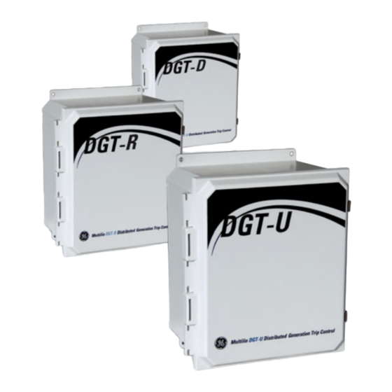
Distributed Generation Trip
Control System
Fast, wireless trip control
Management System is
registered to ISO9001:2000
DGT
I I SO9001:2000
GE Multilin's Quality
QMI # 005094
Table of Contents

Related Manuals for GE Multilin DGT Series


Summary of Contents for GE Multilin DGT Series
- Page 1 Fast, wireless trip control Instruction manual DGT revision: 1.0x Manual P/N: 1601-9045-A1 GE publication code: GEK-113441 Copyright © 2008 GE Multilin GE Multilin 215 Anderson Avenue, Markham, Ontario I I SO9001:2000 Canada L6E 1B3 Tel: (905) 294-6222 Fax: (905) 201-2098 Internet: http://www.GEmultilin.com...
- Page 2 The contents of this manual are the property of GE Multilin Inc. This documentation is furnished on license and may not be reproduced in whole or in part without the permission of GE Multilin. The content of this manual is for informational use only and is subject to change without notice.
-
Page 3: Table Of Contents
TABLE OF CONTENTS Table of contents 1. INTRODUCTION Overview ..........................1 Cautions and warnings ..........................1 Description of DGT system operation.....................2 Description of the DGT system units .......................3 DGT order codes ...............................6 Example of a DGT order code........................6 Standard features ............................6 Options and Accessories..........................7 Specifications ........................8 User interface specifications ........................8 Inputs specifications ............................8... - Page 4 TABLE OF CONTENTS Corrective action ......................49 Firmware updates ......................52 TROUBLESHOOTING Updating the DGT-R firmware .........................52 Updating the DGT-U and DGT-D firmware ..................52 7. DGT INTERCONNECT CABLING 8. REPLACEMENT ASSEMBLIES 1–2 DGT DISTRIBUTED GENERATION TRIP CONTROL SYSTEM – INSTRUCTION MANUAL...
-
Page 5: Introduction
GE Consumer & Industrial Multilin DGT Distributed Generation Trip Control System Chapter 1: Introduction Introduction Overview The DGT Distributed Generation Control System is a wireless communication system designed to transfer Trip Status signals between a Utility’s substation or recloser site and Distributed Generation locations. -
Page 6: Description Of Dgt System Operation
OVERVIEW CHAPTER 1: INTRODUCTION Figure 1-1: Note icons used in the documentation NOTE CAUTION DANGER The standard note icon emphasizes a specific point or indicates minor problems that may occur if instructions are not properly followed. The caution icon indicates that possible damage to equipment or data may occur if instructions are not properly followed. -
Page 7: Description Of The Dgt System Units
CHAPTER 1: INTRODUCTION OVERVIEW The entire round trip time from trip initiation at the substation into the DGT-U to confirmation from the DGT-D occurs in under 150 milliseconds. The integrity of the Trip Status state is maintained through the use of a 32-bit CRC calculation. The CRC prevents the erroneous or malicious manipulation of the Trip Status so that only true data is acted upon. - Page 8 OVERVIEW CHAPTER 1: INTRODUCTION Components in the DGT-U are: • A1 – The DGT-U Radio Transceiver • A2 – The 125 V DC / V AC Power Supply • A3 – 125 V DC Relay for Trip Status Output • A4 –...
- Page 9 CHAPTER 1: INTRODUCTION OVERVIEW • Jumper Cable (not shown) for Connection from Lightning Arrestor to DGT-R Transceiver • Omni-directional Antenna (not shown) • Antenna Feedline (not shown) Figure 1-5: DGT-D layout A3 A4 24 VDC/2.1A 24 VDC/2.1A 24-28 V 24-28 V S O L A S O L A POWER SUPPLY...
-
Page 10: Dgt Order Codes
OVERVIEW CHAPTER 1: INTRODUCTION DGT order codes The information to specify a DGT unit is provided in the following order code figure. Figure 1-6: DGT order codes Example of a DGT order code DGT-RH3: DGT-R unit with 125 V DC / V AC power supply, Omni 7.0 dB antenna, and 150 foot long antenna cable (with connectors). -
Page 11: Options And Accessories
CHAPTER 1: INTRODUCTION OVERVIEW Table 2: Standard features - DGT-R Item Description DGT-R Control unit for Repeater Power supply 125 V DC / V AC (no internal battery or charger) None LEDs 3 (1 power, 1 link, 1 service) Enclosure NEMA 4 Lightning arrester Nominal breakdown voltage 230V... -
Page 12: Specifications
SPECIFICATIONS CHAPTER 1: INTRODUCTION Specifications Specifications are subject to change without notice. NOTE: NOTE User interface specifications GENERAL LED indicators: .............3 LEDs on the DGT-R (located on the internal transceiver module) 6 LEDs on the DGT-D (located on the internal transceiver module) 11 LEDs on the DGT-U (located on the internal transceiver module) -
Page 13: Communications Specifications
CHAPTER 1: INTRODUCTION SPECIFICATIONS Communications specifications RS232 PORT Data transfer rate:..........19.2 kbps Format: ..............8 data bits, no parity bit, 1 stop bit Testing and certification CERTIFICATION ISO:................Manufactured under an ISO9001 registered program CSA: ................DGT radios are approved for Class 1, Division 2 FCC ID:..............E5MDS-EL806 IC ID: ................3738A-MDSEL806 TYPE TESTS... - Page 14 SPECIFICATIONS CHAPTER 1: INTRODUCTION 1–10 DGT DISTRIBUTED GENERATION TRIP CONTROL SYSTEM – INSTRUCTION MANUAL...
-
Page 15: Installation
GE Consumer & Industrial Multilin DGT Distributed Generation Trip Control System Chapter 2: Installation Installation Mechanical installation This section describes the mechanical installation of the DGT system, including dimensions for mounting. Dimensions The dimensions of the DGT unit are shown below. -
Page 16: Installation Considerations
MECHANICAL INSTALLATION CHAPTER 2: INSTALLATION Installation Considerations For a successful installation, careful thought must be given to selecting the proper site for the DGT-D and its antenna system. The location must be able to support antenna mounting at a height and in a direction that provides an unobstructed radio signal transmission path to associated DGT sites. - Page 17 CHAPTER 2: INSTALLATION MECHANICAL INSTALLATION Prepare the mounting surface for the fasteners to be used. (If using lag screws, a small pilot hole at each mark will allow easier starting of the screw.) Insert the 4 mounting screws and tighten them securely. Do not over-tighten. POLE MOUNTING Standard pole mounting requires the use of two pole-mount adapters (P/N 82-1743A01).
-
Page 18: Electrical Installation
ELECTRICAL INSTALLATION CHAPTER 2: INSTALLATION Electrical installation This section describes the connection of external cabling to the DGT-D Assembly. The figures below show overall views of the connection points for all external cabling and wiring. Subsequent illustrations show more detailed views of power connections as required. -
Page 19: Terminal Strip - Power Connections
CHAPTER 2: INSTALLATION ELECTRICAL INSTALLATION Terminal strip - power connections Figure 2-5: DGT (all models) AC & DC power connections (refer to above terminal layouts) 120 V AC Power Connection 24 V DC Power Connection 887003A1.cdr Terminal strip - IO connections Figure 2-6: DGT Terminal strip IO connections (refer to above terminal layouts) DGT DISTRIBUTED GENERATION TRIP CONTROL SYSTEM –... - Page 20 ELECTRICAL INSTALLATION CHAPTER 2: INSTALLATION DGT-U, DGT-D: DGT-D: Terminal Strip - Contact Closure Terminal Strip - Outputs Customer Trip Output Contact Closure Service Output Output Common DGT-U Terminal Strip - Outputs 11 12 Status #1 Output Status #2 Output Status #3 Output Status #4 Output Status #5 Output Status #6 Output...
-
Page 21: Antenna And Feedline Installation
CHAPTER 2: INSTALLATION ANTENNA AND FEEDLINE INSTALLATION Antenna and feedline installation DGT units are ordered with an antenna and feedline package, ready for installation at the station site. A number of standard feedline lengths are available. The length necessary to connect the station antenna to the DGT is determined during the site survey. -
Page 22: Maintaining Regulatory Compliance (Rf Output Power)
RF level from the transceiver is dependent on the gain of the antenna and feedline loss. In all cases, the maximum EIRP from the antenna must not exceed 36 dBm. Contact GE Multilin if assistance is required in determining the maximum output power setting. -
Page 23: User Interface
GE Consumer & Industrial Multilin DGT Distributed Generation Trip Control System Chapter 3: User interface User interface Transceiver layouts DGT-U Transceiver layout PRIMARY POWER 13.8 Vdc @ 350 mA (6 to 30 Vdc) ◆ Negative Ground ◆ 1 + / 2 ◆... - Page 24 TRANSCEIVER LAYOUTS CHAPTER 3: USER INTERFACE within the network. If the output is in a failsafe state, the LED shall flash a unique pattern to indicate this state. • The output LED (OUT-2) illuminates whenever the associated output is energized. OUT-2 will reflect the state of the status input on the DGT-D radio configured for Slot 2 within the network.
- Page 25 CHAPTER 3: USER INTERFACE TRANSCEIVER LAYOUTS DGT-D Transceiver layout PRIMARY POWER 13.8 Vdc @ 350 mA ◆ (6 to 30 Vdc) Negative Ground ◆ TERMINATIONS 1 + / 2 ◆ 1 to 4 24 VDC POWER OUTPUT 5 to 8 24.0 Vdc @ 40 mA ◆...
-
Page 26: Pc Requirements
PC REQUIREMENTS CHAPTER 3: USER INTERFACE PC requirements The following minimum requirements must be met for the EnerVista DGT Setup software to operate on your computer. • Pentium class processor (700 MHz or better recommended) • Microsoft Windows XP / Vista •... -
Page 27: Connecting To A Pc
CHAPTER 3: USER INTERFACE CONNECTING TO A PC Connecting to a PC Figure 3-1: Typical RS232 connection between PC and any DGT radio (DGT-U, DGT-R, or DGT-D) RJ11 Connector DB9 Connector RS232 CONNECTION ANY DGT RADIO DGT DISTRIBUTED GENERATION TRIP CONTROL SYSTEM – INSTRUCTION MANUAL 3–23... - Page 28 CONNECTING TO A PC CHAPTER 3: USER INTERFACE 3–24 DGT DISTRIBUTED GENERATION TRIP CONTROL SYSTEM – INSTRUCTION MANUAL...
-
Page 29: Software
Installing the EnerVista "DGT-DG" Setup software After ensuring the above minimum requirements, use the following procedure to install the EnerVista DGT-DG Setup software from the enclosed GE EnerVista CD or the EnerVista website. Insert the GE EnerVista CD into your CD-ROM drive. - Page 30 ENERVISTA DGT-DG SETUP SOFTWARE CHAPTER 4: SOFTWARE In the EnerVista Launchpad window, click the Add Product button near the top of the window. Only one of the two EnerVista Setup programs - the EnerVista DGT-Utility (used by the NOTE: Utility), or the EnerVista DGT-DG (used by the Distributed Generator), can be loaded on a single computer.
-
Page 31: Dgt-Dg Configuration
CHAPTER 4: SOFTWARE ENERVISTA DGT-DG SETUP SOFTWARE Select the complete path, in your PC, including the new directory name, where the EnerVista DGT-DG Setup software will be installed. Click on Next to begin the installation. The files will be installed in the directory indicated, and the installation program will automatically create icons and add EnerVista DGT-DG Setup software to the Windows start menu. - Page 32 ENERVISTA DGT-DG SETUP SOFTWARE CHAPTER 4: SOFTWARE Once you have installed your EnerVista DGT-DG Setup program, start the program as indicated earlier. The main screen will appear as follows Press the Quick Connect button near the top left edge of the screen. The following window will appear: Using the dropdown box shown above, select the COM port (to which you have connected your communications (RS232) cable) and press the Connect button.
- Page 33 CHAPTER 4: SOFTWARE ENERVISTA DGT-DG SETUP SOFTWARE To bring your distributed generating system online as part of the overall Utility system, select Send Settings File. In the window that appears, go to the folder that you created (in this case, the DGT folder) and select the .hkf file. The file name is composed of two parts: (1) The device number (or "R"...
- Page 34 ENERVISTA DGT-DG SETUP SOFTWARE CHAPTER 4: SOFTWARE Pressing the Save to File button saves the Diagnostics information in a text file, which, if necessary, can be sent to a technical support team for analysis. 10. If you double click upon Status node, the next window will appear: The Status window continuously shows the synchronization state of the DGT system.
-
Page 35: Enervista Dgt-Utility Setup Software
EnerVista DGT-Utility Setup software from the enclosed GE EnerVista CD or the EnerVista web site. Insert the GE EnerVista CD into your CD-ROM drive. Click the Install Now button and follow the installation instructions to install the no- charge EnerVista software on your local PC. - Page 36 ENERVISTA DGT-UTILITY SETUP SOFTWARE CHAPTER 4: SOFTWARE Only one of the two EnerVista Setup programs - the DGT-U (used by the Utility) or the DGT- NOTE: DG (used by the Distributed Generator owner), can be loaded on a single computer. NOTE Select the EnerVista DGT-Utility Setup program as shown above.
-
Page 37: Dgt-Utility Configuration - Creating A Systems File
CHAPTER 4: SOFTWARE ENERVISTA DGT-UTILITY SETUP SOFTWARE 11. To start the EnerVista DGT-Utility Setup application, click on the DGT-Utility icon in the above window. DGT-Utility configuration - Creating a Systems File The EnerVista Setup program for all the DGT units - DGT-U, DGT-U (Recloser), DGT-R, and DGT-D (1 to 7 units) - allows the Utility to handle associated DGT information both on-line and offline. - Page 38 ENERVISTA DGT-UTILITY SETUP SOFTWARE CHAPTER 4: SOFTWARE As indicated in the previous section, open the DGT Utility Setup program: To define the framework of each DGT network, click on File > New System File. The following dialog box will appear: Type in the filename of the system file you are going to create: 4–34 DGT DISTRIBUTED GENERATION TRIP CONTROL SYSTEM –...
- Page 39 CHAPTER 4: SOFTWARE ENERVISTA DGT-UTILITY SETUP SOFTWARE When you click on Save, the following dialog box (form) will appear: Below is an example of a typical form: The first two fields - System Name (minimum 1 character) and Security ID (minimum 2 NOTE: characters) are mandatory fields.
- Page 40 ENERVISTA DGT-UTILITY SETUP SOFTWARE CHAPTER 4: SOFTWARE If an additional DGT-U unit is to be used as a Recloser, the Configure Recloser box must be checked, as follows: Press OK and note that we have just created a new tree’s brunch named “Substation_1,”...
- Page 41 CHAPTER 4: SOFTWARE ENERVISTA DGT-UTILITY SETUP SOFTWARE Clicking on the DGT-R line will bring up the form below which will allow you to enter the name and serial number of the DGT-R, as well as other information: • The top two fields Name and Serial Number are mandatory and should be filled up in NOTE: order to be able to store changes.
- Page 42 ENERVISTA DGT-UTILITY SETUP SOFTWARE CHAPTER 4: SOFTWARE • The top two fields Name and Serial Number are mandatory and should be filled up in NOTE: order to be able to store changes. NOTE • Only the content of these two fields can be uploaded to the device. The rest of the information should be considered as reference data for users only.
- Page 43 CHAPTER 4: SOFTWARE ENERVISTA DGT-UTILITY SETUP SOFTWARE • The top two fields Name and Serial Number are mandatory and should be filled up in NOTE: order to be able to store changes. NOTE • Only the content of these two fields can be uploaded to the device. The rest of the information should be considered as reference data for users only.
-
Page 44: Dgt-Utility Configuration - Creating And Uploading A Settings File
ENERVISTA DGT-UTILITY SETUP SOFTWARE CHAPTER 4: SOFTWARE • The top two fields Name and Serial Number are mandatory and should be filled up in NOTE: order to be able to store changes. NOTE • Only the content of these two fields can be uploaded to the device. The rest of the information should be considered as reference data for users only. - Page 45 CHAPTER 4: SOFTWARE ENERVISTA DGT-UTILITY SETUP SOFTWARE As indicated in the previous section, open the DGT Utility Setup program: In the Offline window, find the System File you have just created. Now lets invesigate the content of the folder. As you can see there are two items – the System File itself and an additional subfolder with the exact the same name as a System File (minus extension) –...
- Page 46 ENERVISTA DGT-UTILITY SETUP SOFTWARE CHAPTER 4: SOFTWARE Let’s take a closer look over the name convention which is in use when the files are created automatically. You will notice that the file name consists of 2 parts: 1 character (letter or digit and a number separated by underscore. Please note that this number is a device serial number (which we input before) and the first character specifies the type of the device.
- Page 47 CHAPTER 4: SOFTWARE ENERVISTA DGT-UTILITY SETUP SOFTWARE It’s always a good idea for the user to create “significant” file names. NOTE: So we now have one extra file in the default System Files folder: NOTE The final stage of the configuration of the DGT System is to upload the newly entered / modified data to the appropriate Device(s).
- Page 48 ENERVISTA DGT-UTILITY SETUP SOFTWARE CHAPTER 4: SOFTWARE Use the Quick Connect button, located just above the Online window, to "find" each of the DGT units (DGT-U, DGT-R, and DGT-D) to which you are connected. Each DGT unit is connected to your COM port using a single removable cable. Select the appropriate COM port and press the Connect button.
- Page 49 CHAPTER 4: SOFTWARE ENERVISTA DGT-UTILITY SETUP SOFTWARE Press the Yes button and the uploading will begin. This process normally takes 20-30 seconds. After it's done, and if the Settings File has been successfully accepted by the device, you will get another message: Information in the Online window will be updated accordingly.
- Page 50 ENERVISTA DGT-UTILITY SETUP SOFTWARE CHAPTER 4: SOFTWARE 13. If a number of changes have been made to Settings Files, send all Settings Files send ALL the Settings Files to the devices to ensure that the devices are operating using the latest file updates.
-
Page 51: Operation
GE Consumer & Industrial Multilin DGT Distributed Generation Trip Control System Chapter 5: Operation Operation Initial power-up When primary power is applied to the DGT-U, DGT-R or DGT-D, the device is ready for configuration or if already configured, for in service operation. Once power is applied check for normal operation by confirming that the red PWR (Power) LED is lit continuously. -
Page 52: Checking For Normal, In-Service, Operation
CHECKING FOR NORMAL, IN-SERVICE, OPERATION CHAPTER 5: OPERATION Checking for normal, in-service, operation Once a DGT Unit is configured and ready for operation please review the following summaries depending upon which type of DGT you are checking. DGT-U Normal Operation •... - Page 53 GE Consumer & Industrial Multilin DGT Distributed Generation Trip Control System Chapter 6: Troubleshooting Troubleshooting Corrective action Please refer to the following tables for a summary of LED error status and possible corrective actions: DGT DISTRIBUTED GENERATION TRIP CONTROL SYSTEM – INSTRUCTION MANUAL...
- Page 54 CORRECTIVE ACTION CHAPTER 6: TROUBLESHOOTING DGT-U Observed Status Meaning Corrective Action PWR (Power) LED Off No power to DGT-U Re-check power source and wiring to the terminal block. • Check that the DGT-R is powered on LINK LED Off No wireless connectivity to DGT-R and fully operational§...
- Page 55 CHAPTER 6: TROUBLESHOOTING CORRECTIVE ACTION DGT-D Observed Status Meaning Corrective Action PWR (Power) LED Off No power to DGT-D Re-check power source and wiring to the terminal block. • Check that the DGT-R is powered on LINK LED Off No wireless connectivity to DGT- and fully operational§...
- Page 56 Updating the DGT-R firmware Please contact GE Multilin for information on DGT-R firmware updates. Updating the DGT-U and DGT-D firmware Please contact GE Multilin for information on DGT-U and DGT-D firmware updates. 6–52 DGT DISTRIBUTED GENERATION TRIP CONTROL SYSTEM – INSTRUCTION MANUAL...
- Page 57 GE Consumer & Industrial Multilin DGT Distributed Generation Trip Control System Chapter 7: DGT interconnect cabling DGT interconnect cabling Figure 7-1: DGT-U wiring TO: A2(-) TO: A2(-) TO: A2(+) TO: A2(+) TO: A14 A28 HEATER A28 HEATER TO: A3(2) TO: A4(2)
- Page 58 CHAPTER 7: DGT INTERCONNECT CABLING Figure 7-2: DGT-R wiring NETio - DG MASTER NETio - DG MASTER TO LIGHTNING ARRESTOR A6 TO LIGHTNING ARRESTOR A6 COM1 COM2 LINK PWR 6-30 VDC(2A max) PWR 6-30 VDC(2A max) HEATER TO: A7(+) TO: A7(-) 24 VDC/2.1A 24 VDC/2.1A 24-28 V...
- Page 59 RJ12 to RJ12 serial cable for connection to DGT-U, DGT-R, and DGT-D Transceivers 73-2434A02 DB9 Female Adaptor for serial cable Please contact GE Multilin for information on components or parts not shown on the list. DGT DISTRIBUTED GENERATION TRIP CONTROL SYSTEM – INSTRUCTION MANUAL 8–55...
- Page 60 CHAPTER 8: REPLACEMENT ASSEMBLIES 8–56 DGT DISTRIBUTED GENERATION TRIP CONTROL SYSTEM – INSTRUCTION MANUAL...