Beko METPOINT FLM SF53 Installation And Operating Manual
Thermal flow meter
Hide thumbs
Also See for METPOINT FLM SF53:
- Installation and operating manual (44 pages) ,
- Installation and operation instruction manual (44 pages)

Related Manuals for Beko METPOINT FLM SF53


Summary of Contents for Beko METPOINT FLM SF53
- Page 1 EN - English Installation and operating manual Thermal flow meter METPOINT FLM SF53 ® FLMSF53LL220 | FLMSF53DL220 | FLMSF53LL400 | FLMSF53DL400...
-
Page 2: Table Of Contents
Installation and operating manual Contents 1. Safety-related information ..........................4 1.1. Pictograms and symbols .......................... 4 1.1.1. In this documentation ................................4 1.1.2. On the device ..................................4 1.2. Signal words ............................4 1.3. Safety instructions ..........................5 1.4. Transport and storage ..........................6 1.5. - Page 3 Installation and operating manual 5. Commissioning ............................. 27 6. Configuration and operation ......................... 27 6.1. Indicators used in operation ........................27 6.2. Setup menu ............................28 6.3. Sensor Setup ............................28 6.3.1. Entering the pipe inner diameter ..........................29 6.3.2. Entering / changing consumption counter value ..................... 29 6.3.3.
-
Page 4: Safety-Related Information
Installation and operating manual 1. Safety-related information 1.1. Pictograms and symbols 1.1.1. In this documentation General instructions Note the installation and operation manual General hazard symbol (danger, warning, caution) General hazard symbol (danger, warning, caution) for mains voltage and mains voltage energised plant and system parts The packaging material is recyclable. -
Page 5: Safety Instructions
Installation and operating manual 1.3. Safety instructions DANGER Escaping compressed gas Risk of serious or even fatal injury from contact with escaping compressed gas or from unsecured plant components. • Depressurise the system before carrying out any assembly, installation or maintenance work. This work must be performed by authorised skilled technical personnel •... -
Page 6: Transport And Storage
Despite our best efforts, transport damage cannot be excluded. Please therefore remove all packaging material immediately after receipt and inspect the product for any possible transport damage. If you detect such damage, immediately notify the carrier company and BEKO TECHNOLOGIES GMBH or one of its agents. CAUTION... -
Page 7: Intended Use
• The METPOINT FLM is primarily used in compressed air systems. On request, the sensor can be programmed by BEKO ® TECHNOLOGIES GmbH for use with other gases: Nitrogen •... -
Page 8: Product Information
Installation and operating manual 2. Product information 2.1. Scope of delivery The table below shows the scope of delivery for the METPOINT FLM. ® Designation Illustration Calibration certificate Connecting cable (5-wire) Alignment tool 2.2. Type plate The type plate is attached to the device housing. The plate lists all of the important data for the METPOINT FLM. -
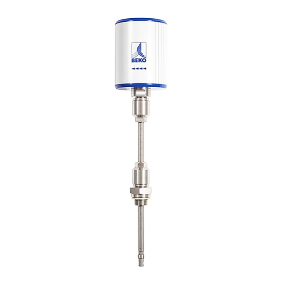
Page 9: Product Overview And Description
Installation and operating manual 2.3. Product overview and description 2.3.1. Identification based on product code D L220 Length of sensor (L) Model with display Interface: RS485 Operating pressure: 50 bar SensorFlow (model designation) FlowMeasurement (product designation) METPOINT SF53 ®... -
Page 10: Product Description
Installation and operating manual 2.3.2. Product description The METPOINT FLM thermal flow meter measures the volume flow, which provides the base data needed for intelligent energy ® management. This can be used to identify potential savings as well overloads or malfunctions and so optimise plant dimensions. The assignment of consumption percentages to production units offers a basis for evidence-based decision-making. -
Page 11: Control And Display Elements
Installation and operating manual 2.4. Control and display elements 2.4.1. Model with display METPOIN T F LM ® Plug-type connector A FLOW MEASURING 395,38 160515 Plug-type connector B HW:1.00 SW:1.00 NOTE Additional information For more information about operation, see “Configuration and operation” on Page 27. 2.4.2. -
Page 12: Direction Of Flow
Installation and operating manual 2.4.3. Direction of flow The direction of flow is indicated by the arrows (1) on the housing of the METPOINT FLM and on its sensor tube. ® NOTE Additional information Turn the housing as necessary (e.g. to change the direction of flow). For more information, see “Turning the housing”... -
Page 13: Dimensions
Installation and operating manual 2.5. Dimensions Dimensions Model with display Model with LED G ½" (ISO 228/1) B (mm) 415 (standard) 418.5 (standard) (mm) Ø 11.7 (mm) E (mm) 220 mm (standard), optional: 400 F (mm) G (mm) 105.5 METPOINT SF53 ®... -
Page 14: Technical Data
Installation and operating manual 2.6. Technical data Technical data SF53 Maximum positive operating 16 bar, optionally 50 bar pressure Measuring technique Calorimetric Operating temperature Sensor tube and fittings: −30 ... +140 °C Housing: −30 ... +80 °C Measuring quantities m³/h (factory settings) On the display version, the following units can be chosen: m³/min, l/min, l/s, ft/min, cfm, m/s, kg/min, kg/s Sensor... -
Page 15: Measuring Ranges
Installation and operating manual 2.7. Measuring ranges The METPOINT FLM can measure flow velocities up to 185.0 m/s and is preconfigured for an inside pipe diameter of 53.1 mm. At ® the analogue output of 4 ... 20 mA, this corresponds to: Rated Inner Ø... - Page 16 Installation and operating manual Rated Inner Ø Volume flow (full scale value in Nm³/h) Max. diameter Inch Air * Air ** 3" 80.0 2781.9 2558.2 2558.2 185.0 82.5 2958.5 2720.6 2720.6 185.0 84.9 3133.1 2881.2 2881.2 185.0 90.0 3525.1 3241.7 3241.7 185.0 4" 100.0 4357.2 4006.9 4006.9 185.0 107.1...
-
Page 17: Set Up
Installation and operating manual 3. Set up 3.1. Warning notices DANGER Escaping compressed gas Risk of serious or even fatal injury from contact with escaping compressed gas or from unsecured plant components. • Depressurise the system before carrying out any set up or maintenance work. Such work must be carried out by authorised skilled technical personnel (see “Safety instructions”... -
Page 18: Turning The Housing
Installation and operating manual 3.1.3. Turning the housing If the direction of flow changes, the housing can be turned to the required position by undoing the 4 threaded pins with a 1.5 mm hex key. Align the housing as required and then tighten the threaded pins so they are hand-tight. NOTE Risk of damage to device •... -
Page 19: Assembly Steps
Installation and operating manual 3.2. Assembly steps The sensor is installed by means of a condensate drain ½, DN 15 ball valve (min. Ø 15 mm). Install the straight fitting with the O-ring (G½ thread, spanner size 32) into the connecting nozzle. Ensure that the installation is pressure-tight. -
Page 20: Electrical Installation
Installation and operating manual 4. Electrical installation 4.1. Pin assignment of plug-type connectors Pin assignment of plug-type connector A, M12 x 1, 5-pin, A-coded (according to EN 61076-2-101) Pin assignment of connector Pin assignment of connector Pin assignment of connector Transmitter side view Bush side view Screw side view... -
Page 21: Current Output 4
Installation and operating manual 4.2.2. Current output 4 ... 20 mA, 3-wire Connection is made using the A plug-type connector. Connection diagram for METPOINT SF53 ® 4 ... 20 mA 4 ... 20 mA Sensor pin assignment Function Wire colour PIN-1 Plus (+) connection, voltage supply brown... -
Page 22: Galvanically Isolated Pulse Output
Installation and operating manual 4.2.4. Galvanically isolated pulse output Connection is made using the B plug-type connector. Connection diagram for METPOINT SF53 ® Impuls Impuls Sensor pin assignment Function Wire colour PIN-1 not assigned brown PIN-2 not assigned white PIN-3 not assigned blue PIN-4... -
Page 23: Connection Of Metpoint
Installation and operating manual 4.3. Connection of METPOINT ® 4.3.1. Bidirectional RS485 bus system Connection is made using the A plug-type connector. Connection diagram for METPOINT SF53 and METPOINT ® ® WHITE BLACK BROWN BLUE RS485 Sensor pin assignment Function Wire colour BDL pin assignment PIN-1... -
Page 24: Current Output 4
Installation and operating manual 4.3.2. Current output 4 ... 20 mA, 3-wire Connection is made using the A plug-type connector. Connection diagram for METPOINT SF53 and METPOINT ® ® BROWN GREY BLUE 4 ... 20 mA Pin assignment - sensor Function Wire colour Pin assignment - BDL... -
Page 25: Connection To Metpoint ® Bdl Compact
Installation and operating manual 4.4. Connection to METPOINT BDL compact ® 4.4.1. Bidirectional RS485 bus system Connection is made using the A plug-type connector. Connection diagram for METPOINT SF53 and METPOINT BDL compact (digital board) ® ® BROWN BLUE WHITE BLACK RS485 BDL compact pin... -
Page 26: Galvanically Isolated Pulse Output
Installation and operating manual 4.4.3. Galvanically isolated pulse output Connection by means of plug-type connector B. Connection diagram for METPOINT SF53 and METPOINT BDL compact (analog board) ® ® BROWN BLACK GREY Impuls BLUE BDL compact pin Pin assignment - sensor Function Wire colour assignment... -
Page 27: Commissioning
Installation and operating manual 5. Commissioning To commission the METPOINT FLM, power it up and perform the sensor setup as described in “Sensor Setup” on Page 28. ® Following this, slowly pressurise the pipes. 6. Configuration and operation After powering up, the METPOINT FLM completes an initialisation procedure and then switches to showing the main menu. -
Page 28: Setup Menu
Installation and operating manual 6.2. Setup menu Press the >>ENTER<< button to call up the setup menu. The setup menu is password-protected. Default password (factory settings): 0000 (4 x zero). If required, change the password by selecting Setup→User Setup→Password Press the >>UP<< button to select and change values. Press the >>ENTER<<... -
Page 29: Entering The Pipe Inner Diameter
Installation and operating manual 6.3.1. Entering the pipe inner diameter Setup → Sensor Setup → Diameter To make changes to the unit (for example), press the >>UP<< button to select the "Unit" field and confirm by pressing the >>ENTER<< button. Press the >>UP<<... -
Page 30: Selecting Units For Consumption, Flow, Temperature And Pressure
Installation and operating manual 6.3.3. Selecting units for consumption, flow, temperature and pressure Setup → Sensor Setup → Units To make changes to the unit (for example), press the >>UP<< button to select the "Unit" field and confirm by pressing the >>ENTER<< button. If there are too many units to fit on one screen, you can use the "<<"... -
Page 31: Entering Reference Conditions
Installation and operating manual 6.3.4. Entering reference conditions Setup → Sensor Setup → Ext. Setup Enter the reference parameter values. Filtertime Setup → Sensor Setup → Ext. Setup → Ref.Pres To make changes to the reference conditions, press the >>UP<< button to select the "Unit"... -
Page 32: Setting Zero Point For Low-Flow Cut-Off Function
Installation and operating manual 6.3.5. Setting zero point for low-flow cut-off function Setup → Sensor Setup → ZP Adjust Enter the zero point and the low-flow cut-off point. Setup → Sensor Setup → ZP Adjust → ZeroPnt If the installed sensor shows a flow rate of > 0 m³/h even if there is no flow, you can enter a zero point for the characteristic. -
Page 33: Modbus Setup
Installation and operating manual 6.4. Modbus setup The METPOINT FLM thermal flow meter is equipped with an RS-485 interface (Modbus RTU). Before starting the sensor, ® configure the communication parameters • Modbus ID, baud rate, parity and stop bit to enable communication with the Modbus master. Setup →... -
Page 34: Modbus Settings (2001
Installation and operating manual 6.4.1. Modbus settings (2001 ... 2005) Modbus Register Read/ Byte Data type Description Default Unit/comment register address write 2001 2000 UInt16 Modbus ID Modbus ID 1…247 0 = 1200 1 = 2400 2 = 4800 2002 2001 UInt16 Baud rate... -
Page 35: Pulse / Alarm
Installation and operating manual 6.5. Pulse / alarm Setup → Pulse/Alarm The galvanically isolated pulse output can be used as a pulse or as an alarm output. The following units can be selected for the alarm output: • kg/min, cfm, l/s, m³/h, m/s, °F, °C, kg/s Press "Value"... -
Page 36: User Setup
Installation and operating manual 6.6. User Setup Setup → User Setup On the user setup screen, you can change the password, rotate the display and adjust its brightness. To change the password, you must enter the new password twice. 6.7. Advanced Setup →... - Page 37 Installation and operating manual 6.8. 4 ... 20 mA Setup → 4 - 20 mA On this screen, you can adjust the settings for the 4 ... 20 mA analogue output. Setup → 4 - 20 mA → Channel 1 The following measurement data can be configured: •...
-
Page 38: Info
Installation and operating manual Setup → 4 - 20 mA → Error Current On this screen, you can enter the error signal to be sent by the analogue output in the event of a fault. • 2 mA = sensor fault/system error •... -
Page 39: Spare Parts And Accessories
10. Recalibration Unless otherwise agreed with the customer, we recommend having the device calibrated every 12 months. For calibration, send the METPOINT FLM to BEKO TECHNOLOGIES GmbH. ® 11. LED display A calibration reminder LED is mounted on the top of the housing of the METPOINT ®... - Page 40 Installation and operating manual METPOINT SF53 ®...
-
Page 41: Declaration Of Conformity
Installation and operating manual 12. Declaration of Conformity METPOINT SF53 ®... - Page 42 Installation and operating manual BEKO TECHNOLOGIES GMBH Im Taubental 7 41468 Neuss, GERMANY Phone: +49 2131 988-0 www.beko-technologies.com EU Declaration of Conformity We hereby declare that the products named below comply with the stipulations of the relevant directives and technical standards. This declaration only refers to products in the condition in which they have been placed into circulation.
- Page 43 Installation and operating manual METPOINT SF53 ®...
- Page 44 Tel. +81 44 328 76 01 [email protected] [email protected] BEKO TECHNOLOGIES S. de R.L. de C. BEKO TECHNOLOGIES CORP. BEKO Technologies, S de R.L. de C.V. 900 Great Southwest Pkwy SW Blvd. Vito Alessio Robles 4602 Bodega 10 US - Atlanta, GA 30336 Zona Industrial Tel.