Sharp XL-30H Service Manual
Micro component system
Hide thumbs
Also See for XL-30H:
- Quick manual (4 pages) ,
- Service manual (64 pages) ,
- Operation manual (25 pages)
Table of Contents
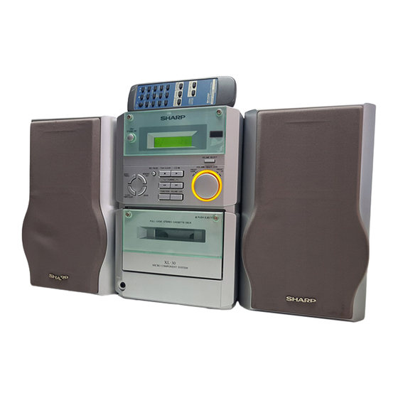
Illustration: XL-30H
Illustration: XL-30W
SAFETY PRECAUTION FOR SERVICE MANUAL .......................................................................................................... 2
IMPORTANT SERVICE NOTES (XL-30H FOR U.K. ONLY) ............................................................................................ 3
VOLTAGE SELECTION (FOR XL-30W) ........................................................................................................................... 3
AC POWER SUPPLY CORD AND AC PLUG ADAPTOR (FOR XL-30W) ....................................................................... 3
SPECIFICATIONS ............................................................................................................................................................ 4
NAMES OF PARTS .......................................................................................................................................................... 5
OPERATION MANUAL ..................................................................................................................................................... 6
DISASSEMBLY ............................................................................................................................................................... 10
REMOVING AND REINSTALLING THE MAIN PARTS .................................................................................................. 11
ADJUSTMENT ................................................................................................................................................................ 13
TEST MODE ................................................................................................................................................................... 14
ERROR LIST .................................................................................................................................................................. 18
NOTES ON SCHEMATIC DIAGRAM ............................................................................................................................. 19
TYPES OF TRANSISTOR AND LED .............................................................................................................................. 19
BLOCK DIAGRAM .......................................................................................................................................................... 20
SCHEMATIC DIAGRAM ................................................................................................................................................. 24
WIRING SIDE OF P.W.BOARD ...................................................................................................................................... 30
WAVEFORMS OF CD CIRCUIT ..................................................................................................................................... 37
TROUBLESHOOTING .................................................................................................................................................... 38
FUNCTION TABLE OF IC .............................................................................................................................................. 44
LCD SEGMENT .............................................................................................................................................................. 52
PARTS GUIDE/EXPLODED VIEW
All manuals and user guides at all-guides.com
SERVICE MANUAL
CONTENTS
SHARP CORPORATION
- 1 -
MICRO COMPONENT SYSTEM
MODEL
XL-30H Micro Component System consisting of XL-30H (main unit)
and CP-XL40H (speaker system).
XL-30W
MODEL
XL-30W Micro Component System consisting of XL-30W (main unit)
and CP-XL40H (speaker system).
• In the interests of user-safety the set should be restored to its original
condition and only parts identical to those specified should be used.
• Note for users in U.K.
Recording and playback of any material may require consent,
which SHARP is unable to give. Please refer particularly to the
provisions of Copyright Act 1956, the Dramatic and Musical
Performers Protection Act 1956, the Performers Protection Acts
1963 and 1972 and to any subsequent statutory enactments and
orders.
This document has been published to be used
for after sales service only.
The contents are subject to change without notice.
XL-30H/30W
No. S5046XL30HW//
XL-30H
Page
Table of Contents

Related Manuals for Sharp XL-30H


Summary of Contents for Sharp XL-30H
-
Page 1: Table Of Contents
• Note for users in U.K. Recording and playback of any material may require consent, which SHARP is unable to give. Please refer particularly to the provisions of Copyright Act 1956, the Dramatic and Musical Performers Protection Act 1956, the Performers Protection Acts 1963 and 1972 and to any subsequent statutory enactments and orders. -
Page 2: Safety Precaution For Service Manual
As the laser beam used in this compact disc player is harmful to the eyes, do not attempt to disassem- ble the cabinet. Refer servicing to qualified person- nel only. (XL-30H for Europe) (XL-30H for U.K.) – 2 –... -
Page 3: Important Service Notes (Xl-30H For U.k. Only)
All manuals and user guides at all-guides.com XL-30H/30W IMPORTANT SERVICE NOTES (XL-30H FOR U.K. ONLY) Before returning the unit to the customer after completion of a repair or adjustment it is necessary for the following withstand voltage test to be applied to ensure the unit is safe for the customer to use. -
Page 4: Specifications
50/60 Hz D/A converter: 1-bit D/A converter Filter: 8-times oversampling digital Power consump- 26 W filter tion: (For XL-30H) Frequency response: 20 - 20,000 Hz Power consump- Wow and flutter: Unmeasurable tion: (For XL-30W) 28 W (less than 0.001% W. peak) Dimensions: Width;... -
Page 5: Names Of Parts
All manuals and user guides at all-guides.com XL-30H/30W NAMES OF PARTS XL-30H/30W Front panel 1. Timer Indicator 2. Record Indicator 3. Sleep Indicator 4. (CD) Repeat Indicator 5. (CD) Play Indicator 6. (CD) Random Indicator 7. (CD/TUNER) Memory Indicator 8. FM Stereo Mode Indicator 9. -
Page 6: Operation Manual
All manuals and user guides at all-guides.com XL-30H/30W XL-30H/30W Remote control 1. Remote Control Transmitter LED Tuner control section 2. Preset Up/Down Buttons CD control section 3. Clear Button 4. Random/Repeat Button 5. Memory Button 6. Stop Button 7. Play/Pause Button 8. - Page 7 All manuals and user guides at all-guides.com XL-30H/30W – 7 –...
- Page 8 All manuals and user guides at all-guides.com XL-30H/30W – 8 –...
- Page 9 All manuals and user guides at all-guides.com XL-30H/30W – 9 –...
-
Page 10: Disassembly
All manuals and user guides at all-guides.com XL-30H/30W DISASSEMBLY XL-30H/30W Caution on Disassembly Follow the below-mentioned notes when disassembling (A1)x1 Top Cabinet the unit and reassembling it, to keep it safe and ensure ø3x10mm CD PWB excellent performance: (B2)x1 1. Take cassette tape and compact disc out of the unit. -
Page 11: Removing And Reinstalling The Main Parts
All manuals and user guides at all-guides.com XL-30H/30W CP-XL40H Speaker Box PROCEDURE STEP REMOVAL FIGURE (A1x1) Speaker 1. Front panel ..(A1) x1 11-1 Woofer 2. Screw ....(A2) x4 (A2)x4 ø4x12mm Driver should be Note: pried away from Driver After removing the connector for the optical pickup from the speaker Box. - Page 12 All manuals and user guides at all-guides.com XL-30H/30W (E1)x1 How to remove the flywheel (See Fig. 12-1.) Stop Washer Mechanism 1. Remove the belt. Chassis 2. Remove the stop washer (E1) x 1 pc., with a small precision Driver Stop screwdriver to extract the flywheel from the capstan metal.
-
Page 13: Adjustment
*1. Adjust so that an output signal appears. Play: TW-2111 30 to 60 g. cm Fast forward: TW-2231 55 to 140 g.cm • FM Mute Level (For XL-30H) Rewind: TW-2231 55 to 140 g.cm Signal generator: 1 kHz, 40 kHz dev., FM modulated Display... -
Page 14: Test Mode
All manuals and user guides at all-guides.com XL-30H/30W • Setting the Test Mode (For XL-30W) • Setting the Test Mode (For XL-30H) Keeping the FF/FWD button and MEMORY button pressed, Keeping the FF/FWD button and MEMORY/SET button turn on POWER. Then, the frequency is initially set in the pressed, turn on POWER. - Page 15 All manuals and user guides at all-guides.com XL-30H/30W * In case of initialization the pickup is moved toward the inner periphery. Any buttons other than "POWER" button are not accepted until the shift of pickup to the inner periphery is completed at this time. If PU-IN SW ON cannot be detected within 10 seconds, the slide motor is stopped, and the following error indication appears.
- Page 16 All manuals and user guides at all-guides.com XL-30H/30W 5. Step 5 Mode The CD initialization operation flow is executed to the end, the mute is set to off, and playback is started. Even when the playback reaches the outermost periphery of disc, the operation does not stop. The LCD display indicates the playback past time as in case of ordinary CD playback.
- Page 17 All manuals and user guides at all-guides.com XL-30H/30W 3. Preset frequencies for various destinations (random preset memory) (For XL-30H) BAND Europe 2, 4 Europe 2, 4 BAND Europe 2, 4 BAND 16-25 FM 87.50 MHz AM 522 kHz FM108.00 MHz AM1620 kHz FM106.00 MHz...
-
Page 18: Error List
All manuals and user guides at all-guides.com XL-30H/30W 7. Key input diagnosis Test Mode (TEST 6) When the test mode is set, the following indication appears. This test mode is intended to check whether all the main unit buttons can be detected. Accordingly, in this test mode checking as to whether the "POWER"... -
Page 19: Notes On Schematic Diagram
All manuals and user guides at all-guides.com XL-30H/30W NOTES ON SCHEMATIC DIAGRAM • Resistor: • The indicated voltage in each section is the one measured To differentiate the units of resistors, such symbol as K and by Digital Multimeter between such a section and the chas- M are used: the symbol K means 1000 ohm and the symbol sis with no signal given. -
Page 20: Block Diagram
14 13 ONLY IC303 T306 FM IF DET./FM MPX./AM IF AM OSC. VD301-2 SVC348S LA1832 CNP301 AM/FM ANTENNA TERMINALS AM IF FOR XL-30H T351 ZD351 CF351 MTZJ5.1B FM IF CF352 A_12V A_GND Q305 10.7MHz CF302 FM IF AMP. FM IF... - Page 21 D_GND REC L/R CH D681~D684 AUDIO 12V LF651 Q604 LINE (A_12V) TAPE L/R CH FILTER Q603 T681 SUB POWER FOR XL-30H SO651 TRANSFORMER AC POWER INPUT SOCKET AC230V,50Hz T651 MAIN POWER D651~D654 TRANSFORMER F651 VOLTAGE REGULATOR T2.5A L 250V F653...
- Page 22 All manuals and user guides at all-guides.com XL-30H/30W LCD701 LCD DISPLAY D704-709 COM3 COM2 CFW701 COM1 SEG27 COM0 SEG28 VLC3 SEG29 D_GND VLC2 SEG30 VLC1 SEG31 SEG32 SWITCHING OSC2 SEG33 A_12V OSC1 Q707 X701 IC701 8MHz LED+B BUCK IX0027SJ BUS3...
- Page 23 All manuals and user guides at all-guides.com XL-30H/30W LCD DISPLAY CL ID_SW SEG25 CD_RES SEG26 SEG27 BUCK SEG28 BUS3 SEG29 BUS2 TO CD PWB SEG30 BUS1 SEG31 BUS0 SEG32 CD_STB SEG33 PU_IN IC701 BUCK CNS702 IX0027SJ BUS3 YSTEM CONTROL BUS2...
-
Page 24: Schematic Diagram
All manuals and user guides at all-guides.com XL-30H/30W XL-30H XL-30W 3.3K R363 6.8K R364 6.8K 3.3K AM TRACKING AM ANT C330 FM MUTE LEVEL 12P(CH) R358 VR351 C332 C331 8.2K VD301 10K(B) 0.022 0.047 4.7V T302 SVC348S (0V) C371 L353... - Page 25 IC601 6 GR R603 LA4600 J601 HEADPHONES R616 IC601 6.8K POWER AMP. R604 LA4600 HEADPHONS 12.9V PWB-A5 C614 R602 POWER PWB-B for XL-30H 1000/25 T651 1.4V 9.8V MAIN POWER 1.7V TRANSFORMER C606 C697 C699 C616 4.7/25 0.001 0.0033 D651 4700/25...
- Page 26 SW709 2.4V PWB-A7 ON/STAND-BY X702 32.768kHz 1.9V C705 C701 C702 0.001 MMOD (CH) (CH) VREF SW700 R724 XL-30H: 1.2K CLID_SW R731 XL-30W: 5.6K KEY1 R732 IC702 KEY2 C706 R733 LOADING MOTOR DRIVER 0.001 MODEL TA7291S R734 C705,C706 XL-30W ONLY CLID_PRO...
- Page 27 All manuals and user guides at all-guides.com XL-30H/30W DISPLAY PWB-A2 LCD701 LCD DISPLAY 99 98 97 96 95 94 93 92 91 90 89 88 87 86 85 84 83 82 81 80 79 78 77 76 SEG24 SEG25 2.5V SEG26 2.5V...
- Page 28 All manuals and user guides at all-guides.com XL-30H/30W CD SIGNAL PU_IN CD_STB BUS0 BUS1 BUS2 BUS3 BUCK CLID_SW L803 R813 10µH R814 R817 R818 3.3K C824 0.056 C825 C823 R812 C819 C821 0.056 0.01 3.3K C833 C834 470P 470P C822...
- Page 29 All manuals and user guides at all-guides.com XL-30H/30W CD PWB-A3 CFW807 SW801 OPEN/CLOSE OPEN/CLOSE SWITCH PWB-A6 C861 0.001 CD_L A_GND CD_R L804 TO MAIN PWB 2.2µH M_GND CNP605 M_12V P25 7-H D_GND Q861 CD_6R2V L803 2SB562 C 10µH 6.3V L801 10µH...
-
Page 30: Wiring Side Of P.w.board
All manuals and user guides at all-guides.com XL-30H/30W XL-30H SO601 FROM SPEAKER POWER AM/FM LOOP TERMINALS ANTENNA R-CH L-CH CNS652 P36 2-A ANTENNA CNP301 TERMINAL 1 2 3 C376 C301 BF301 Q305 C397 E C B C614 C304 C316 R381... - Page 31 All manuals and user guides at all-guides.com XL-30H/30W XL-30W ANTENNA TERMINALS FROM SO601 SPEAKER POWER AM LOOP ANTENNA SO301 TERMINALS ANTENNA FM 75 OHMS R-CH L-CH CNS652 P36 2-E CNP301 C376 C301 BF301 Q305 C397 E C B C614 C304...
- Page 32 All manuals and user guides at all-guides.com XL-30H/30W XL-30H DISPLAY PWB-A2 TO MAIN PWB P30 6-H CNP703 R746 R743 R778 R747 R775 R741 1 2 3 4 5 6 7 8 9 10 11 R779 R740 CNS703 CNS702 CLOCK/TIMER/ SW722...
- Page 33 All manuals and user guides at all-guides.com XL-30H/30W XL-30W DISPLAY PWB-A2 TO MAIN PWB P31 12-H CNP703 R746 R743 R778 R747 R775 1 2 3 4 5 6 7 8 9 10 11 R741 R779 R740 CNS703 CNS702 CLOCK/TIMER/ SW722...
- Page 34 All manuals and user guides at all-guides.com XL-30H/30W XL-30H PICKUP UNIT CD MOTOR PWB-C NSW801 PICK UP IN NM802 SPINDLE MOTOR NM801 SLED MOTOR OPEN/CLOSE TO MAIN PWB SWITCH PWB-A6 CFW807 P30 1-G CNP605 SW801 CNS605 CNS803 1 2 3 4 5 6 7...
- Page 35 All manuals and user guides at all-guides.com XL-30H/30W XL-30W PICKUP UNIT CD MOTOR PWB-C NSW801 PICK UP IN NM802 SPINDLE MOTOR NM801 SLED MOTOR OPEN/CLOSE TO MAIN PWB SWITCH PWB-A6 CFW807 P31 7-G CNP605 SW801 CNS605 CNS803 1 2 3 4 5 6 7...
- Page 36 P30 1-A When servicing, pay attention as the area DISPLAY PWB P32 5-G enclosed by this line ( ) is directly CNS707 CNS652 POWER PWB-B (XL-30H) connected with AC main voltage. BI652 CNP681 R685 R686 Q683 E C B C688...
-
Page 37: Waveforms Of Cd Circuit
All manuals and user guides at all-guides.com XL-30H/30W WAVEFORMS OF CD CIRCUIT NO DISC FOCUS SEARCH STOP PLAY TMAX IC802 48pin IC802 30pin SBOK IC804 26pin IC802 12pin IC804 25pin IC802 55pin FOCUS SEARCH TOC IL STOP PLAY IC802 57pin... -
Page 38: Troubleshooting
All manuals and user guides at all-guides.com XL-30H/30W TROUBLESHOOTING When the CD does not function When the CD section does not operate when the objective lens of the optical pickup is dirty, this section may not operate. Clean the objective lens, and check the playback operation. When this section does not operate even after the above step is taken, check the following items. - Page 39 All manuals and user guides at all-guides.com XL-30H/30W Make sure that the disc is normal, and set the CD TEST MODE (STEP 1). Is the measured voltage as specified in circuit diagram? Check the main unit power supply circuit. Is "Er-CD01" displayed"? Move the pickup to most internal circumference side of disc.
- Page 40 All manuals and user guides at all-guides.com XL-30H/30W • Laser failure. Is +6.2V applied to the emitter of Q861 ? Check the PWB pattern between pin 16 of CNS602 and emitter of Q861. Check the peripheral parts of IC804 and Q861.
- Page 41 All manuals and user guides at all-guides.com XL-30H/30W • Focus servo sawtooth wave failure. IC802 is faulty. Is sawtooh wave output to the pin 48 (FOO) of IC802 ? 1.5~2.5sec Check the PWB pattern between pin 16 of CNS602 and IC804.
- Page 42 All manuals and user guides at all-guides.com XL-30H/30W • HF error. Is output (tracking error signal) obtained at the pins 46 (TEI) Optical pickup failure. Is output obtained at the pins 2 and and 47 (TEZI) of IC802 the CD TEST MODE "STEP 4" is 5 of BI802/CNS802 changed to "STEP 5"?
- Page 43 All manuals and user guides at all-guides.com XL-30H/30W • Track search failure Does the sled motor run in FF/REW state when the SERVO Check as stated in item "SLED MOTOR OPERATION FAILURE". TEST MODE "STEP1" is set? Is the following wave output to the pin 49 (TRO) of IC802 IC802 failure.
-
Page 44: Function Table Of Ic
All manuals and user guides at all-guides.com XL-30H/30W FUNCTION TABLE OF IC IC401 VHiLC75342M-1: Function/Volume Equalizer (LC75342M) Pin No. Port Name Function Serial data and clock input pin for control. Chip enable pin. Data written into an internal latch in a timing of [H] -> [L]. Each analog switch is activated. - Page 45 All manuals and user guides at all-guides.com XL-30H/30W IC701 RH-iX0027SJZZ: System Control Microcomputer (IX0027SJ) (1/2) Terminal Name Input/Output Function Pin No. COM3-COM0 Output LCD common output terminal. VLC3-VLC1 — LCD power supply terminal. — Microcomputer power supply +5V. OSC2 Output Oscillator ground terminal for main clock.
- Page 46 All manuals and user guides at all-guides.com XL-30H/30W IC701 RH-iX0027SJZZ: System Control Microcomputer (IX0027SJ) (2/2) Terminal Name Input/Output Function Pin No. SEG46 P63/A3 Output Electric JOG dial UP. SEG45 P64/A4 Output Electric JOG dial DOWN. SEG44 P65/A5 Output Electric CD lid OPEN.
- Page 47 All manuals and user guides at all-guides.com XL-30H/30W IC801 VHiTA2109F/-1:Servo Pre Amp. (TA2109F) Pin No. Terminal Name Input/Output Function — Power voltage terminal Input Main beam amp input terminal Input Main beam amp input terminal Input Sub-beam amp input terminal...
- Page 48 All manuals and user guides at all-guides.com XL-30H/30W IC802 VHiTC9462F/-1: Servo/Signal Control (TC9462F) (1/3) Function Port Name Input/Output Pin No. TEST0 Input Test mode terminal. To be opened usually. /HSO Output Playback speed mode flag output terminal. /UHSO Output /UHSO...
- Page 49 All manuals and user guides at all-guides.com XL-30H/30W IC802 VHiTC9462F/-1: Servo/Signal Control (TC9462F) (2/3) Function Port Name Input/Output Pin No. AVDD — Analog system power terminal. RFCT Input RFRP signal center level input terminal. RFZI Input RFRP zero cross input terminal.
- Page 50 All manuals and user guides at all-guides.com XL-30H/30W IC802 VHiTC9462F/-1: Servo/Signal Control (TC9462F) (3/3) Input/Output Function Port Name Pin No. DVDD — D/A converting section power terminal. — Reference voltage terminal. Output L channel data forward rotation output terminal. DVSL —...
- Page 51 All manuals and user guides at all-guides.com XL-30H/30W IC804 VHiLA6541D/-1: Focus/Tracking/Spin/Sled Driver (LA6541D) Pin No. Port Name Function Power (short-circuited to pin 30) MUTE All BTL AMP output ON/OFF VIN1 BTL AMP1 input terminal BTL AMP1 input terminal (for gain adjustment)
-
Page 52: Lcd Segment
All manuals and user guides at all-guides.com XL-30H/30W LCD701: RV-LX0008SJZZ LCD Display 1 2 3 4 5 6 7 8 9 10 11 12 13 14 15 16 17 18 19 20 21 22 23 24 PinNo com1 com2 com3... - Page 53 All manuals and user guides at all-guides.com XL-30H/30W PARTS GUIDE MICRO COMPONENT SYSTEM XL-30H MODEL XL-30H Micro Component System consisting of XL-30H (main unit) and CP-XL40H (speaker system). XL-30W MODEL XL-30W Micro Component System consisting of XL-30W (main unit) and CP-XL40H (speaker system).
- Page 54 IC601 VHILA4600//-1 AN Power Amp.,LA4600 CF351 RFILF0003AWZZ AK FM IF IC682 VHIKIA7805P-1 AF Voltage Regulator,KIA7805P LF651 RCILZ0002SJZZ AG Line Filter [XL-30H Only] [XL-30W Only] IC701 RH-IX0027SJZZ AW System Control Microcomputer, TRANSFORMERS IX0027SJ IC702 VHITA7291S/-1 AH Loading Motor Driver,TA7291S CF352 RFILA0003SJZZ...
- Page 55 AB 47 µF,16V,Electrolytic C315 VCKYTV1HB101K AA 100 pF,50V C685 RC-GZA476AF1C AB 10 µF,16V,Electrolytic C316 RC-GZA106AF1C [XL-30H Only] AA 0.022 µF,25V AB 0.022 µF,50V [XL-30H Only] C317 VCKYTV1EF223Z C686 VCKYPA1HF223Z AB 0.047 µF,50V,Thin Film C318 VCCSTV1HL5R0J AA 5 pF,50V C688 VCFYFA1HA473J...
- Page 56 R125 VRS-TV2AB104J AA 100 kohm,1/10W R661,662 VRD-ST2EE331J AA 330 ohms,1/4W R126 VRS-TV2AB562J AA 5.6 kohms,1/10W R681 VRD-ST2CD470J AA 47 ohms,1/6W [XL-30H Only] R131 VRD-ST2CD472J AA 4.7 kohms,1/6W R682 VRD-ST2CD122J AA 1.2 kohms,1/6W [XL-30H Only] R132 VRS-TV2AB472J AA 4.7 kohms,1/10W R683...
- Page 57 AE Switch,Leaf Type [Fool Proof] SW902(237-8) 9GD640101210 AE Switch,Leaf Type [Cam] BI605/CNS605 QCNWN0179SJZZ J AF Connector Ass’y,7/7Pin CD MECHANISM PARTS BI652/CNS652 QCNWN0178SJZZ J AC Connector Ass’y,2/2Pin [XL-30H] BI652/CNS652 QCNWN0195SJZZ J Connector Ass’y,3/3Pin [XL-30W] NGERH0586AFZZ AC Gear,Middle BI702/CNS702 QCNWN0180SJZZ J AE Connector Ass’y,10/10Pin...
- Page 58 AG Cassette Holder XJBSD30P10000 AA Screw,ø3×10mm [XL-30W Only] 201- 7 HDECP0003SJSA AF Decoration Plate,LCD Display 201- 8 HDECP0002SJSA AF Decoration Plate,Cassette ACCESSORIES/PACKING PARTS (For XL-30H) Holder 201- 9 HDECQ0028SJSA AE LCD Window QACCE0001SJZZ AH AC Power Supply Cord 201-10 HDECQ0029SJSA...
- Page 59 AD Cushion,Speaker 9GDYFY978B010 AH Cord,Speaker 9GDYFY090B008 AF Label,Specifications SP601,602 VSD0010PBY24N Speaker,Full-Range PACKING PARTS SPAKA0031SJZZ Pad,Speaker [XL-30H for Europe Only] SPAKC0088SJZZ Packing Case,Speaker [XL-30H for Europe Only] SPAKP0006SJZZ Polyethylene Bag,Speaker [XL-30H for Europe] SPAKZ0008SJZZ Pad,Bottom,Speaker [XL-30H for Europe Only] SPAKZ0009SJZZ Pad,Center,Speaker...
- Page 60 All manuals and user guides at all-guides.com XL-30H/30W XL-30H/30W 306-2 306-1 306-3 703x2 NM802 NM801 305x2 NSW801 PWB-C Figure 7 CD MECHANISM EXPLODED VIEW – 7 –...
- Page 61 All manuals and user guides at all-guides.com XL-30H/30W XL-30H 216-2 216-1 BELT CONNECTION Motor(M901) 613x2 FF/REW Clutch Main 610x2 Belt PWB-A7 PWB-A4 FF/REW Flywheel Belt PWB-A2 PWB-A8x3 603 601x2 M701 PWB-A6 601x3 608x2 MECHANISM LCD701 609x3 609x3 PWB-A3 610x2 605x2...
- Page 62 All manuals and user guides at all-guides.com XL-30H/30W XL-30W 216-2 216-1 BELT CONNECTION Motor(M901) 613x2 FF/REW Clutch Main 610x2 Belt PWB-A7 PWB-A4 FF/REW Flywheel Belt PWB-A2 PWB-A8x3 603 601x2 M701 PWB-A6 601x3 608x2 MECHANISM LCD701 609x3 609x3 PWB-A3 XL-30W ONLY...
- Page 63 All manuals and user guides at all-guides.com XL-30H/30W CP-XL40H SP601(L-CH) SP602(R-CH) 704x4 FULL-RANGE SPEAKER SP601(L-CH) SP602(R-CH) BLACK BLACK WITH WHITE LINE Figure 10 SPEAKER EXPLODED VIEW – 10 –...
-
Page 64: Packing Method (Xl-30H For U.k. Only)
All manuals and user guides at all-guides.com XL-30H/30W PACKING OF METHOD (XL-30H FOR U.K. ONLY) XL-30H CP-XL40H 1. AC Power Supply Cord QACCB0001SJ00 1. Polyethylene Bag, Speaker 9GDYFY978B013 2. AM/FM Loop Antenna QANTL0003SJZZ 2. Packing Add., Top/Bottom, SPAKA0044SJZZ 3. Ecology Label...