
Related Manuals for Beko BEKOMAT 31U IF built-in F


Summary of Contents for Beko BEKOMAT 31U IF built-in F
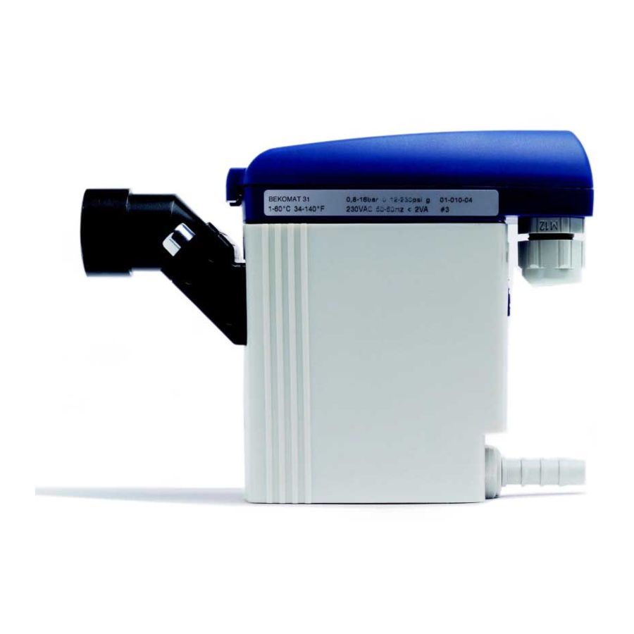
- Page 1 EN - english Instructions for installation and operation Condensate drain ® BEKOMAT 31U IF built-in F (BM31UIFBIF)
- Page 2 Dear customer, Thank you for deciding in favour of the BEKOMAT ® 31U IF built-in F condensate drain. Please read the installation and operating instructions carefully before mounting and starting up the BEKOMAT ® 31U IF built-in F, and follow our directions. Perfect functioning of ®...
-
Page 3: Table Of Contents
Pictograms and symbols ........................4 Safety instructions ..........................4 Proper use .............................. 6 Exclusion from the scope of application ....................6 Technical data ............................7 Electrical data ............................7 ... -
Page 4: Pictograms And Symbols
Any deviation involves a risk for persons and materials, and may result in malfunction and service failures. If you have any queries regarding these installation- and operating instructions, please contact BEKO TECHNOLOGIES GMBH. BEKOMAT® 31U IF built-in F... - Page 5 Safety instructions Danger! Compressed air! Risk of serious injury or death through contact with quickly or suddenly escaping compressed air or through bursting plant components or plant components which are not secured. Measures: • Do not exceed the maximum operating pressure (see type plate). •...
-
Page 6: Proper Use
Proper use Proper use • The BEKOMAT ® 31U IF built-in F is an electronically level-controlled condensate drain for compressed-air plants. • The device is employed within the permissible performance parameters (see "Technical data"). • The BEKOMAT ® 31U IF built-in F is able to drain condensate under operating pressure from the plant components virtually without compressed-air loss. -
Page 7: Technical Data
Technical data Technical data min./max. operating pressure 0,8...16 bar (12...230 psi) min./max. temperature +1...+70 °C (+34...+158 °F) G ½ (NPT ½) internal Condensate inflow max. screw-in depth 13,5 mm (½") Condensate outflow G ¼ Ø 8 ... 10 mm hose connector Condensate oil-contaminated + oil-free Housing... -
Page 8: Dimension Drawing
Dimension drawing Dimension drawing 0,9 ± 0,1 Nm mm (inch) BEKOMAT® 31U IF built-in F... -
Page 9: Function
Function Function Via the inlet line (1) the condensate flows into the BEKOMAT ® 31U IF and accumulates in the housing (2). A capacitively functioning sensor (3) continuously registers the filling level and releases a signal to the electronic interface (output Sen), as soon as the container is filled. -
Page 10: Installation
Installation Installation Danger! Compressed air! Risk of serious injury or death through contact with quickly or suddenly escaping compressed air or through bursting plant components or plant components which are not secured. Measures: • Do not exceed the maximum operating pressure (see type plate). •... - Page 11 Installation Note: It is imperative to observe all hazard statements and warnings listed here. Please also observe all regulations and notes regarding industrial safety and fire prevention at the place of installation. As a matter of principle, only use suitable and appropriate tools and materials in a proper condition. Do not use aggressive cleaners and improper devices such as high-pressure cleaners.
- Page 12 Installation wrong correct Pressure differences! Each condensate accumulation point must be drained separately. Continuous slope! Avoid a water pocket when installing the feed pipe Deflector area! If drainage is to be carried out directly from the pipe, deflection of the air flow will be useful. Ventilation! If the slope in the inlet line is not sufficient or if any other inflow problems occur, a venting line needs to...
-
Page 13: Electrical Installation
Electrical installation 10 Electrical installation Note: 1. Only use a protective extra-low voltage (PELV) in accordance with IEC 60364-4-41. 2. Carry out installation in accordance with VDE 0100 / IEC 60364. 3. Observe the terminal assignment. 4. Unscrew the screw (1) and remove upper part of the cover (2). - Page 14 Electrical installation Note: Between the terminals and the housing or the condensate connections, there is no galvanic isolation. The provided 24 VDC voltage must comply with the requirements for protective extra-low voltages (PELV) in accordance with IEC 60364-4-41. Tighten the threaded cable connection with a slightly sealing effect. Electric diagram BEKOMAT®...
-
Page 15: Inspection And Maintenance
Inspection and maintenance 11 Inspection and maintenance Danger! Compressed air! Risk of serious injury or death through contact with quickly or suddenly escaping compressed air or through bursting plant components or plant components which are not secured. Measures: • Do not exceed the maximum operating pressure (see type plate). •... - Page 16 Inspection and maintenance Note: It is imperative to observe all hazard statements and warnings listed here. Please also observe all regulations and notes regarding industrial safety and fire prevention at the place of installation. As a matter of principle, only use suitable and appropriate tools and materials in a proper condition. Do not use aggressive cleaners and improper devices such as high-pressure cleaners.
- Page 17 Inspection and maintenance Installation of the control unit on the service unit: 1. Check whether or not the service unit (5) goes with the control unit (1) (model designation and colour of the arresting hook). 2. Check whether or not the sealing mat (11) and the contact springs (13) are clean, dry, and free from impurities.
-
Page 18: Troubleshooting And Fault Elimination
Troubleshooting and fault elimination 12 Troubleshooting and fault elimination Symptoms Possible reasons Measures Supply voltage incorrect Check the connections and the supply voltage Circuit board defective No detectable function Check the circuit board for possible External control defective damage Replace the circuit board Feed and/or discharge pipe Check feed and discharge pipe blocked or obstructed... -
Page 19: Elements And Components
Elements and components 13 Elements and components 1 Screw 3.5 x 10 7 Cable bushing 2 Upper part of the cover 8 Sealing mat 3 Moulded gasket 9 Service unit 4 Circuit board 10 Hose connector 5 Sensor 11 O-ring 20 x 2 6 Lower part of the cover 14 Recommended spare parts Available sets of spare parts... -
Page 20: Declaration Of Conformity
Declaration of conformity 15 Declaration of conformity BEKOMAT® 31U IF built-in F... - Page 21 Declaration of conformity BEKO TECHNOLOGIES GMBH Im Taubental 7 41468 Neuss GERMANY Phone: +49 2131 988-0 www.beko-technologies.com EU Declaration of Conformity We hereby declare that the products named below comply with the stipulations of the relevant directives and technical standards. This declaration only refers to products in the condition in which they have been placed into circulation.
- Page 22 A M Angle nozzle 16 Maintenance 15 Maintenance recommendation 16 B Malfunction 18 Blows off 18 Membrane 9 C Mounting 10 Circuit board 19 N Circuit board defective 18 No condensate discharge 18 Components 19 No function 18 Condensate discharge disturbed 18 No sensor signal 18 Control unit 16 O ...
- Page 23 BEKOMAT® 31U IF built-in F...
- Page 24 Italia / Italy Polska / Poland 日本 / Japan BEKO TECHNOLOGIES S.r.l BEKO TECHNOLOGIES Sp. z o.o. BEKO TECHNOLOGIES K.K Via Peano 86/88 ul. Pańska 73 KEIHIN THINK Building 8 Floor I - 10040 Leinì (TO) PL - 00-834 Warszawa 1-1 Minamiwatarida-machi Tel.