ABB IRC5 Compact Product Manual
Hide thumbs
Also See for IRC5 Compact:
- Operating manual (590 pages) ,
- Product manual (550 pages) ,
- Applications manual (110 pages)
Table of Contents
Table of Contents

Related Manuals for ABB IRC5 Compact


Summary of Contents for ABB IRC5 Compact
- Page 1 ROBOTICS Product manual IRC5 Compact...
- Page 2 Trace back information: Workspace 20B version a7 Checked in 2020-05-07 Skribenta version 5.3.033...
- Page 3 Product manual IRC5 Compact Design 14 Document ID: 3HAC047138-001 Revision: M © Copyright 2009-2020 ABB. All rights reserved. Specifications subject to change without notice.
- Page 4 Except as may be expressly stated anywhere in this manual, nothing herein shall be construed as any kind of guarantee or warranty by ABB for losses, damage to persons or property, fitness for a specific purpose or the like.
-
Page 5: Table Of Contents
Buttons and switches on the front panel ............2.5.1.1 Brake release button ..............Connections ..................... 2.6.1 Connectors on the IRC5 Compact controller ..........2.6.1.1 Connectors on the controller ............2.6.1.2 Connecting a FlexPendant ............2.6.1.3 Connectors on the computer unit ............ - Page 6 2.11.3 Installation of conveyor tracking module ............2.11.4 Installing the Safety module DSQC1015 for SafeMove ........2.11.5 Installing the Connected Services box ............2.12 Testing ......................Maintenance Maintenance schedule, IRC5 Compact controller ............ Inspection activities ................... 3.2.1 Inspection of controller ................Changing/replacing activities ................
- Page 7 Standard toolkit, IRC5 ..................Screw joints ..................... Spare parts IRC5 Compact controller ..................FlexPendant parts ..................... Manipulator cables .................... Circuit diagrams Circuit diagrams ....................Index Product manual - IRC5 Compact 3HAC047138-001 Revision: M © Copyright 2009-2020 ABB. All rights reserved.
- Page 8 This page is intentionally left blank...
-
Page 9: Overview Of This Manual
• maintenance personnel. • repair personnel. Prerequisites Maintenance/repair/installation personnel working with an ABB Robot must: • be trained by ABB and have the required knowledge of mechanical and electrical installation/repair/maintenance work. References Reference Document ID Product manual - IRC5 3HAC047136-001... - Page 10 Added information that function tests should be performed after repla- cing a component. • Changes in the article names for some spare parts. • Removed section Refurbish. Continues on next page Product manual - IRC5 Compact 3HAC047138-001 Revision: M © Copyright 2009-2020 ABB. All rights reserved.
- Page 11 Added note in section Replacement of SD-card memory in computer unit on page 163, that SD-card from DSQC1018 cannot be used in DSQC1024. Continues on next page Product manual - IRC5 Compact 3HAC047138-001 Revision: M © Copyright 2009-2020 ABB. All rights reserved.
- Page 12 Published in release 20B. The following updates are made in this revision: • Information regarding power supply system requirements has been improved in sections Isolation transformer on page 68 Mains line filter on page Product manual - IRC5 Compact 3HAC047138-001 Revision: M © Copyright 2009-2020 ABB. All rights reserved.
-
Page 13: Product Documentation
Product documentation Categories for user documentation from ABB Robotics The user documentation from ABB Robotics is divided into a number of categories. This listing is based on the type of information in the documents, regardless of whether the products are standard or optional. - Page 14 The operating manuals describe hands-on handling of the products. The manuals are aimed at those having first-hand operational contact with the product, that is production cell operators, programmers, and troubleshooters. Product manual - IRC5 Compact 3HAC047138-001 Revision: M © Copyright 2009-2020 ABB. All rights reserved.
-
Page 15: Network Security
ABB Ltd and its entities are not liable for damage and/or loss related to such security breaches, any unauthorized access, interference, intrusion, leakage and/or theft of data or information. - Page 16 This page is intentionally left blank...
-
Page 17: Safety
The installation and/or use of non-original spare parts and equipment can negatively affect the safety, function, performance, and structural properties of the robot. ABB is not liable for damages caused by the use of non-original spare parts and equipment. -
Page 18: Safety Data
The safety related parts of robot and controller are e.g. the following stop circuits: • Enabling device • Emergency stop on operator panel Continues on next page Product manual - IRC5 Compact 3HAC047138-001 Revision: M © Copyright 2009-2020 ABB. All rights reserved. - Page 19 DC have been calculated according to EN ISO 13849-1 Annex C, D and E resulting in the values as specified in the following table. See the SISTEMA/ABB FSDT libraries for details of the safety functions. IRC5C Compact Safety function...
- Page 20 EN ISO 13849-1 and thus fulfils the safety performance requirement of the robot safety standard EN ISO 10218-1. The Common Cause Failure (CCF) is met according to the standard requirements. Product manual - IRC5 Compact 3HAC047138-001 Revision: M © Copyright 2009-2020 ABB. All rights reserved.
-
Page 21: Requirements On Personnel
The plant liable must make sure that the personnel is trained on the robot, and on responding to emergency or abnormal situations. Personal protective equipment Use personal protective equipment, as stated in the product manual. Product manual - IRC5 Compact 3HAC047138-001 Revision: M © Copyright 2009-2020 ABB. All rights reserved. -
Page 22: Safety Signals And Symbols
DISCHARGE (ESD) situation which, if not avoided, could result in severe damage to the product. NOTE Signal word used to indicate important facts and conditions. Product manual - IRC5 Compact 3HAC047138-001 Revision: M © Copyright 2009-2020 ABB. All rights reserved. -
Page 23: Safety Symbols On Controller Labels
The information labels can contain information in text. Symbols on safety labels Label Description Read the user manual before use. xx1400001152 CE label xx1800000835 Continues on next page Product manual - IRC5 Compact 3HAC047138-001 Revision: M © Copyright 2009-2020 ABB. All rights reserved. - Page 24 UL certified (robot with controller) xx1400002061 Rating label (example) xx1400001163 Lifting instruction for the IRC5 controller. xx1400001157 Required installation space. xx1400001155 Continues on next page Product manual - IRC5 Compact 3HAC047138-001 Revision: M © Copyright 2009-2020 ABB. All rights reserved.
- Page 25 UL mains switch). xx1700000354 High voltage inside the module even if the main switch is in the OFF position. xx1400001156 ESD sensitive components inside the controller. xx1400001162 Product manual - IRC5 Compact 3HAC047138-001 Revision: M © Copyright 2009-2020 ABB. All rights reserved.
-
Page 26: Robot Stopping Functions
The safety input Superior Stop is operational in both manual mode and automatic mode. The default configuration is stop category 1. (Superior stop is only available for IRC5.) Continues on next page Product manual - IRC5 Compact 3HAC047138-001 Revision: M © Copyright 2009-2020 ABB. All rights reserved. - Page 27 SoftSS can be used to configure the protective stop in automatic and manual mode, either as stop category 0 or category 1. The default configuration is TRUE (stop category 1). Product manual - IRC5 Compact 3HAC047138-001 Revision: M © Copyright 2009-2020 ABB. All rights reserved.
-
Page 28: About Emergency Stops
After actuation and before disengaging the emergency stop device, the machinery shall be inspected in order to detect the reason for actuation. Product manual - IRC5 Compact 3HAC047138-001 Revision: M © Copyright 2009-2020 ABB. All rights reserved. -
Page 29: Enabling Device And Hold-To-Run Functionality
Note The manual full speed mode is not available in all markets. Deviations are listed in the product manual for the manipulator. Product manual - IRC5 Compact 3HAC047138-001 Revision: M © Copyright 2009-2020 ABB. All rights reserved. -
Page 30: Robot Operating Modes
Manual high speed mode (optional) Safeguard mechanisms • Protective stops through Three-position enabling switch General Stop, GS Deviations are listed in the product manual for the controller. Product manual - IRC5 Compact 3HAC047138-001 Revision: M © Copyright 2009-2020 ABB. All rights reserved. -
Page 31: About The Automatic Mode
Safeguard mechanisms • Protective stop through Automatic Stop, AS General Stop, GS Superior Stop, SS Deviations are listed in the product manual for the controller. Product manual - IRC5 Compact 3HAC047138-001 Revision: M © Copyright 2009-2020 ABB. All rights reserved. -
Page 32: Installation And Commissioning
When the robot is installed at a height, hanging, or other than mounted directly on the floor, there will be additional hazards. Electrical safety The mains power must be installed to fulfill national regulations. Continues on next page Product manual - IRC5 Compact 3HAC047138-001 Revision: M © Copyright 2009-2020 ABB. All rights reserved. - Page 33 Before the robot system is put into operation, verify that the safety functions are working as intended and that any remaining hazards identified in the risk assessment are mitigated to an acceptable level. Product manual - IRC5 Compact 3HAC047138-001 Revision: M © Copyright 2009-2020 ABB. All rights reserved.
-
Page 34: Operation
These must be stored out of reach and sight so that they cannot be mistaken for being in use. Product manual - IRC5 Compact 3HAC047138-001 Revision: M © Copyright 2009-2020 ABB. All rights reserved. -
Page 35: Maintenance And Repair
See safety instructions for the batteries in Material/product safety data sheet - Battery pack (3HAC043118-001). Related information See also the safety information related to installation and operation. Product manual - IRC5 Compact 3HAC047138-001 Revision: M © Copyright 2009-2020 ABB. All rights reserved. -
Page 36: Troubleshooting
The manipulator can move unexpectedly at any time. DANGER Troubleshooting on the controller while powered on must be performed by personnel trained by ABB or by ABB field engineers. A risk assessment must be done to address both robot and robot system specific hazards. -
Page 37: Decommissioning
1 Safety 1.9 Decommissioning 1.9 Decommissioning General See section Decommissioning on page 203. Product manual - IRC5 Compact 3HAC047138-001 Revision: M © Copyright 2009-2020 ABB. All rights reserved. - Page 38 This page is intentionally left blank...
-
Page 39: Installation And Commissioning
Note When replacing a unit in the controller, report the following data to ABB, for both the replaced unit and the replacement unit: • the serial number •... -
Page 40: Installation Activities
IRC5 Compact controller is described in section Unpacking the controller on page Install the IRC5 Compact controller. How to install the IRC5 Compact controller is described in section On-site installation on page Connect the manipulator to the IRC5 How to connect the manipulator to the Compact controller. -
Page 41: Unpacking The Controller
The table below shows the protection classes for the IRC5 controller and the FlexPendant: Equipment Protection class IRC5 Compact controller IP20 Continues on next page Product manual - IRC5 Compact 3HAC047138-001 Revision: M © Copyright 2009-2020 ABB. All rights reserved. - Page 42 2 Installation and commissioning 2.3 Unpacking the controller Continued Equipment Protection class FlexPendant IP54 Product manual - IRC5 Compact 3HAC047138-001 Revision: M © Copyright 2009-2020 ABB. All rights reserved.
-
Page 43: On-Site Installation
2 Installation and commissioning 2.4.1 Required installation space 2.4 On-site installation 2.4.1 Required installation space Dimensions The following illustration shows the required installation space for the IRC5 Compact controller. xx1400001367 Not required if the controller is rack-mounted • A free space of 50 mm on both left and right side of the controller is required if the controller is mounted on desk (not rack-mounted). - Page 44 The feet should only be used for positioning, not for mounting or fastening. Note If the IRC5 Compact controller is to be installed in a rack, it must be fastened in a way that prevents distortion of the controller cabinet. Preferably with angle bars along the entire side edges of the controller cabinet.
-
Page 45: Mounting The Flexpendant Holder
Do not position the FlexPendant holder so that it is an obstacle in the place of work. Required equipment Equipment Art.no FlexPendant holder For spare parts, see Miscellaneous parts on page 214. Continues on next page Product manual - IRC5 Compact 3HAC047138-001 Revision: M © Copyright 2009-2020 ABB. All rights reserved. - Page 46 The surface must be clean and dry. Note For rack mounted IRC5 Compact, do not place the FlexPendant holder on top of the rack. Find a solution where the FlexPendant is placed so that it cannot fall to the floor from a high position.
-
Page 47: Mounting The Controller In A 19" Cabinet
2 Installation and commissioning 2.4.3 Mounting the controller in a 19" cabinet 2.4.3 Mounting the controller in a 19" cabinet General The IRC5 Compact controller is designed to fit in a 19" cabinet. xx1400002112 Required equipment Equipment Information Mounting kit... - Page 48 Fit the right, left and middle mounting brackets in the 19 inch cabinet. xx1500000232 Insert the IRC5 Compact in the 19 inch cab- inet so that the latches fit in the recesses in the back of the mounting brackets. Fasten the IRC5 Compact to the mounting brackets with the attachment screws.
-
Page 49: The Unit Is Sensitive To Esd
The mat must be grounded through a current-limit- ing resistor. Use a dissipative table mat. The mat should provide a controlled discharge of static voltages and must be grounded. Product manual - IRC5 Compact 3HAC047138-001 Revision: M © Copyright 2009-2020 ABB. All rights reserved. -
Page 50: Buttons And Switches
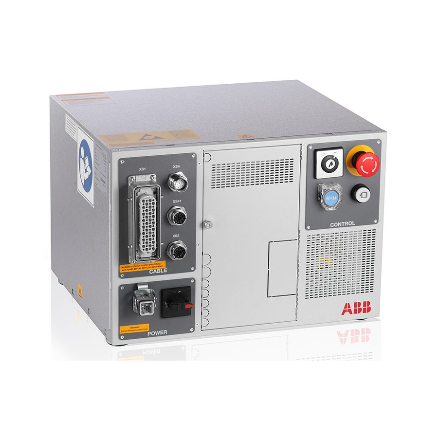
IRC5 Compact controller. xx1400001369 Main power switch Brake release button (under the cover) for IRB 120. The IRC5 Compact used with other robots has no brake release button, only a blanking plug, since the robot has a brake release button. -
Page 51: Brake Release Button
Brake release button (under the cover) for IRB 120. IRB 120 An IRC5 Compact controller used with IRB 120 has a brake release button located under a plastic cover. At power on state, open the cover and press the brake release button to change the positions of the manipulator axes manually. -
Page 52: Connections
CAUTION Always inspect the connector for dirt or damage before connecting it to the controller. Clean or replace any damaged parts. Connectors The following details the connection interface on the IRC5 Compact. xx1400001372 Description XS.4 FlexPendant connection Continues on next page... - Page 53 2 Installation and commissioning 2.6.1.1 Connectors on the controller Continued Description XS.1 Robot power connection XS.41 Additional axes SMB connection XS.2 Robot SMB connection XP.0 Mains connection Product manual - IRC5 Compact 3HAC047138-001 Revision: M © Copyright 2009-2020 ABB. All rights reserved.
-
Page 54: Connecting A Flexpendant
Plug in the FlexPendant cable connector. Screw the connector lock ring firmly by turning it clockwise. Continues on next page Product manual - IRC5 Compact 3HAC047138-001 Revision: M © Copyright 2009-2020 ABB. All rights reserved. - Page 55 9.5 mm then it is allowed to roll it with a radius of 95 mm. Extension cables are not allowed to be used in chains. Product manual - IRC5 Compact 3HAC047138-001 Revision: M © Copyright 2009-2020 ABB. All rights reserved.
-
Page 56: Connectors On The Computer Unit
Service port test middle The service port is intended for service engineers and programmers connecting directly to the controller with a PC. Continues on next page Product manual - IRC5 Compact 3HAC047138-001 Revision: M © Copyright 2009-2020 ABB. All rights reserved. - Page 57 The LAN 2 and LAN 3 ports are intended for connecting network based process equipment to the controller. For example field buses, cameras, and welding equipment. Continues on next page Product manual - IRC5 Compact 3HAC047138-001 Revision: M © Copyright 2009-2020 ABB. All rights reserved.
- Page 58 It is recommended to use the USB ports USB and USB on the X10 connector for connecting USB memory devices. The USB ports on the X11 connector are intended for internal use. Product manual - IRC5 Compact 3HAC047138-001 Revision: M © Copyright 2009-2020 ABB. All rights reserved.
-
Page 59: Connecting A Serial Channel To The Controller
The serial channel connector is located on the expansion board in the computer unit as shown below. xx1300000610 COM1 CONSOLE Note The CONSOLE connector is used for debugging purposes only. Continues on next page Product manual - IRC5 Compact 3HAC047138-001 Revision: M © Copyright 2009-2020 ABB. All rights reserved. - Page 60 Connect the adapter to the serial channel A cable is needed between the serial connector. channel connector and the adapter. xx1300000854 A cable B adapter Product manual - IRC5 Compact 3HAC047138-001 Revision: M © Copyright 2009-2020 ABB. All rights reserved.
-
Page 61: Connecting Cables To The Controller
Shielded cable with twisted pair conductors. A specific cable signals should be used for field bus connections and Ethernet, according to the standard specification of the respective bus. Continues on next page Product manual - IRC5 Compact 3HAC047138-001 Revision: M © Copyright 2009-2020 ABB. All rights reserved. - Page 62 If the grounding points have different electric potentials - grounding both ends will create a ground loop allowing unwanted current to flow in the shield. Continues on next page Product manual - IRC5 Compact 3HAC047138-001 Revision: M © Copyright 2009-2020 ABB. All rights reserved.
- Page 63 Shield pigtail termination, as shown below, shall be avoided. If a pigtail connection cannot be avoided, make it as short as possible. xx1700001321 Continues on next page Product manual - IRC5 Compact 3HAC047138-001 Revision: M © Copyright 2009-2020 ABB. All rights reserved.
- Page 64 IEC 61000-5-2. For details of cross-sectional area of PE refer to IEC 60204-1. Grounding installation For information on how to install the ground for the IRC5 Compact controller cabinet, Grounding on page For information on how to install the ground for the manipulator, see the corresponding product manual.
- Page 65 The screens of the 2 cables must be connected as shown in the figure, but not connected to the chassis of the unit. Continues on next page Product manual - IRC5 Compact 3HAC047138-001 Revision: M © Copyright 2009-2020 ABB. All rights reserved.
- Page 66 V max voltage and 125 V nominal voltage. The resistor should be 100 Ω, and the capacitor should be 1W 0.1 - 1 µF (typically 0.47 µF). Product manual - IRC5 Compact 3HAC047138-001 Revision: M © Copyright 2009-2020 ABB. All rights reserved.
-
Page 67: Power Supply System Requirements
PE and an N conductor. xx1700001311 xx1700001310 Not recommended power supply systems The following systems are not recommended by ABB: TT system (separate ground rods) Resistance grounded secondary system If this kind of system must be used, the If this kind of system must be used, the... - Page 68 TT system (separate ground rods) Resistance grounded secondary system xx1700001312 xx1700001313 Not allowed power supply systems The following systems are not allowed by ABB: Un-symmetric system IT system (ungrounded secondary) These transformers provide un-symmetric The voltage between phases and ground is phase voltages with respect to ground.
- Page 69 A Primary/input B Secondary/output Mains line filter A mains line filter is included in the IRC5 Compact controller, ensuring compliance with EN/IEC 61000-6-4. Additional types of external filters may be used, provided they are approved by regional standards. For further information refer to regional power supply standards.
-
Page 70: Connecting Power Supply
The following illustration shows the location of the power input connector on the front panel of the controller. xx1400001372 Description XS.4 FlexPendant connection XS.1 Robot power connection XS.41 Additional axes SMB connection Continues on next page Product manual - IRC5 Compact 3HAC047138-001 Revision: M © Copyright 2009-2020 ABB. All rights reserved. - Page 71 The following procedure describes how to connect the mains power to the controller. Action Connect the power cable from the power supply to connector XP0 on the front panel of the controller. Product manual - IRC5 Compact 3HAC047138-001 Revision: M © Copyright 2009-2020 ABB. All rights reserved.
-
Page 72: Grounding
The following procedure describes how to connect the mains power to the controller. Action Connect single-phase power supply and PE wire to the XP0 connector. Product manual - IRC5 Compact 3HAC047138-001 Revision: M © Copyright 2009-2020 ABB. All rights reserved. -
Page 73: Fitting The Connector
This section describes how to manufacture a cable for connecting the mains power to the controller. Specifications The following describes the cable and fuse requirements for the mains power connection to the IRC5 Compact controller. Component Description Cable type Flexible oil resistant rubber Cable area 3 x 2.5 mm... - Page 74 • X0.2 - zero line • X0.PE - earth wire Assemble the connector by fitting the hood and the female connector, and tighten the screws. Product manual - IRC5 Compact 3HAC047138-001 Revision: M © Copyright 2009-2020 ABB. All rights reserved.
-
Page 75: Descriptions For Connectors Xs7 - Xs17
221. Note Safety male connectors are delivered with Compact controller. The bridge connector can be bought from ABB (3HAC051190-001). If it is bought from the manufacturer, see Circuit diagrams on page 221 for connection details. Continues on next page... - Page 76 It contains 16 digital input and output signals of DSQC 652. It contains 24V, 0V for outputs and 0V for input of DSQC 651 or DSQC 652. For connection details, see circuit diagram for IRC5 Compact, see Circuit diagrams on page 221.
- Page 77 24V power supply Note Total customer usage for 24V power supply from XS16 must not exceed 6A. For connection details, see circuit diagram for IRC5 Compact controller. Note Power male connector are delivered with Compact controller. The power connector is included in the same cable as DeviceNet connector (3HAC054250-001).
- Page 78 This connector is internally connected with Profibus - master bus. It contains a Profibus signal. For connection details, see circuit diagram for IRC5 Compact controller. Product manual - IRC5 Compact 3HAC047138-001 Revision: M © Copyright 2009-2020 ABB. All rights reserved.
-
Page 79: The Motors On/Motors Off Circuit
GS (general mode safeguarded space stop) AS (Automatic mode safeguarded space stop) ED (FlexPendant three-position enabling device) Manual mode Automatic mode Operating mode selector Motor Continues on next page Product manual - IRC5 Compact 3HAC047138-001 Revision: M © Copyright 2009-2020 ABB. All rights reserved. - Page 80 X15.5 Opto X15.3 isol. Terminal Location xx1600000281 Technical data per chain Limit switch Load: 300 mV Max. voltage drop: 1 V Continues on next page Product manual - IRC5 Compact 3HAC047138-001 Revision: M © Copyright 2009-2020 ABB. All rights reserved.
- Page 81 Safety PLC IRC5 Compact Safety board (A21) Safety relay Contact X9 X9.30 (AS1+) X9.31 (24 V) X9.22 (AS2-) X9.20 (0 V) en0900000482 Continues on next page Product manual - IRC5 Compact 3HAC047138-001 Revision: M © Copyright 2009-2020 ABB. All rights reserved.
- Page 82 X2:8 X2:6 X2:5 X2:4 X2:2 X2:3 xx1000001009 Internal Ext stop FlexPendant Cabinet ES1 internal Run chain 1 top Internal ES2 internal Continues on next page Product manual - IRC5 Compact 3HAC047138-001 Revision: M © Copyright 2009-2020 ABB. All rights reserved.
- Page 83 Rated current per chain 40 mA Max. potential in relation to the cabinet earthing 300 V and other signal groups. Signal class Control signals Product manual - IRC5 Compact 3HAC047138-001 Revision: M © Copyright 2009-2020 ABB. All rights reserved.
-
Page 84: Programmable Stop Functions
Note Only safety rated input signals are allowed to be used for safety. Continues on next page Product manual - IRC5 Compact 3HAC047138-001 Revision: M © Copyright 2009-2020 ABB. All rights reserved. - Page 85 The Program Pointer will be moved to Main and if run- ning mode is continuous, the pro- gram will be restarted. Continues on next page Product manual - IRC5 Compact 3HAC047138-001 Revision: M © Copyright 2009-2020 ABB. All rights reserved.
- Page 86 The robot might make a limited move when restarted. WARNING The revolution counters might need to be updated after a colli- sion to ensure path accuracy. Product manual - IRC5 Compact 3HAC047138-001 Revision: M © Copyright 2009-2020 ABB. All rights reserved.
-
Page 87: Emergency Stop Output
The diagram below shows the connection of a safety relay, type RT6 from Jokab Safety. ABB Robotics does not offer the safety relay option. The safety relay can be purchased from Jokab Safety or Pilz. -
Page 88: Opening The Irc5 Compact Controller
2 Installation and commissioning 2.7 Opening the IRC5 Compact controller 2.7 Opening the IRC5 Compact controller Removing the controller cover Action Info/illustration DANGER Before any work inside the cabinet, read the safety information in section Electrical safety on page Remove the attachment screws on the cover. -
Page 89: Drive System
2 Installation and commissioning 2.8.1 Drive functions, general 2.8 Drive system 2.8.1 Drive functions, general General The robot is powered by power electronics found in the IRC5 Compact controller. Location of drive unit xx1400001373 Main Drive Unit Replacing drive system parts... -
Page 90: Memory Functions
2.9 Memory functions 2.9.1 Memory functions General The controller is fitted with an SD-card memory containing ABB Boot Application software. The SD-card memory is located inside the computer unit. For more information on how to replace the SD-card memory, see... -
Page 91: Connecting A Usb Memory
The location of the USB port on the FlexPendant is shown by the following illustration: xx0900000022 USB port (located behind rubber cover) Continues on next page Product manual - IRC5 Compact 3HAC047138-001 Revision: M © Copyright 2009-2020 ABB. All rights reserved. - Page 92 2 Installation and commissioning 2.9.2 Connecting a USB memory Continued Location on the controller The location of the USB ports on the IRC5 Compact controller is shown by the following illustration: xx1400001376 USB port 1 - 4 Product manual - IRC5 Compact 3HAC047138-001 Revision: M ©...
-
Page 93: I/O System
The following master/slave boards are available: Description Art. no. Type designation PROFIBUS Master PCIexpress 3HAC044872-001 DSQC1005 DeviceNet Master/Slave PCIexpress 3HAC043383-001 DSQC1006 Continues on next page Product manual - IRC5 Compact 3HAC047138-001 Revision: M © Copyright 2009-2020 ABB. All rights reserved. - Page 94 Assembled expansion board for fieldbus adapters, without adapter. Description Art. no. Type designation AnybusCC / RS232 expansion 3HAC046408-001 DSQC1003 board Continues on next page Product manual - IRC5 Compact 3HAC047138-001 Revision: M © Copyright 2009-2020 ABB. All rights reserved.
- Page 95 Application manual - EtherNet/IP Scanner/Adapter 3HAC050998-001 Application manual - PROFIBUS Anybus Device 3HAC050965-001 Application manual - PROFIBUS Controller 3HAC050966-001 Application manual - PROFIenergy Device 3HAC050967-001 Continues on next page Product manual - IRC5 Compact 3HAC047138-001 Revision: M © Copyright 2009-2020 ABB. All rights reserved.
- Page 96 2 Installation and commissioning 2.10.1 Definition of fieldbuses, IRC5 Continued Manual title Art. no. Application manual - PROFINET Anybus Device 3HAC050968-001 Application manual - PROFINET Controller/Device 3HAC065546-001 Product manual - IRC5 Compact 3HAC047138-001 Revision: M © Copyright 2009-2020 ABB. All rights reserved.
-
Page 97: Devicenet I/O Units
Detailed descriptions of all available The application manual for the different I/O buses re- DeviceNet I/O units. spectively, see listing in Definition of fieldbuses, IRC5 on page Product manual - IRC5 Compact 3HAC047138-001 Revision: M © Copyright 2009-2020 ABB. All rights reserved. -
Page 98: Conveyor Tracking Module
The connector kit in- cludes contacts for 2 encoders and 4 camer- Two connector kits are needed to handle additional encoders and cameras. Continues on next page Product manual - IRC5 Compact 3HAC047138-001 Revision: M © Copyright 2009-2020 ABB. All rights reserved. - Page 99 The table below gives references to additional information: Information: Found in: How to install and configure Convey- Application manual - Conveyor tracking, or Tracking. 3HAC050991-001 Product manual - IRC5 Compact 3HAC047138-001 Revision: M © Copyright 2009-2020 ABB. All rights reserved.
-
Page 100: Installation Of Add-Ons
Wall cabinet IRC5 3HAC038671-001 External Operator's panel 3HAC065947-001 cable 3HAC065947-004 15 m 3HAC065947-005 30 m Circuit diagram Circuit diagrams on page 221. Continues on next page Product manual - IRC5 Compact 3HAC047138-001 Revision: M © Copyright 2009-2020 ABB. All rights reserved. - Page 101 Fit the cable from the external operator's panel harness to the controller through the hole for Emergency stop button and tighten the cable gland. xx1000000956 Continues on next page Product manual - IRC5 Compact 3HAC047138-001 Revision: M © Copyright 2009-2020 ABB. All rights reserved.
- Page 102 Connect the connectors and earth cable inside the wall cabinet. Mount the front panel of the external oper- ator's panel on the wall cabinet with four attachment screws. Product manual - IRC5 Compact 3HAC047138-001 Revision: M © Copyright 2009-2020 ABB. All rights reserved.
-
Page 103: Installation Of External Enabling Device
Overview IRC5 is delivered with one enabling device but have the possibility to connect one additional external enabling device (cannot be ordered from ABB Robotics). When an external enabling device is used together with the three-position enabling device on the teach pendant, both enabling devices must be enabled to be able to operate the manipulator in manual mode. - Page 104 IRC5’s enabling device chain’s Diagnostic Coverage is medium (90% < DCavg < 99%). • The Common Cause Failure (CCF) is met according to the standard requirements. Product manual - IRC5 Compact 3HAC047138-001 Revision: M © Copyright 2009-2020 ABB. All rights reserved.
-
Page 105: Installation Of Conveyor Tracking Module
3HNA027579-001 CONNECTOR KIT - DSQC 2000 3HNA029345-001 Application manual - Conveyor 3HAC050991-001 tracking Standard toolkit Standard toolkit, IRC5 on page 209. Continues on next page Product manual - IRC5 Compact 3HAC047138-001 Revision: M © Copyright 2009-2020 ABB. All rights reserved. - Page 106 Ethernet network as ule. the robot controllers. Connect wires to the encoder and camera Described in the Application manual - Con- connectors as required. veyor tracking. Product manual - IRC5 Compact 3HAC047138-001 Revision: M © Copyright 2009-2020 ABB. All rights reserved.
-
Page 107: Installing The Safety Module Dsqc1015 For Safemove
Harness 24 V I/O DSQC1015 3HAC057073-001 Harness auxiliary contact 3HAC057076-001 Harness Emergency stop 3HAC032324-001 Harness Control (Motor on, Key switch) 3HAC049563-001 Continues on next page Product manual - IRC5 Compact 3HAC047138-001 Revision: M © Copyright 2009-2020 ABB. All rights reserved. - Page 108 A Attachment screws (4 pcs.) B Cover Remove the attachment screw on top of the slot bracket. Continues on next page Product manual - IRC5 Compact 3HAC047138-001 Revision: M © Copyright 2009-2020 ABB. All rights reserved.
- Page 109 The fan cable must not be squeezed. xx1300000684 A Attachment screws (4 pcs.) B Cover Connect all cables according to the proced- ures described below. Continues on next page Product manual - IRC5 Compact 3HAC047138-001 Revision: M © Copyright 2009-2020 ABB. All rights reserved.
- Page 110 Connect connector G2.X3 on 24 V I/O harness (D) to power distribution unit (G2). Connect safety hard Key switch harness (A2) connectors X14 and X15 to the safety board (A21). Continues on next page Product manual - IRC5 Compact 3HAC047138-001 Revision: M © Copyright 2009-2020 ABB. All rights reserved.
- Page 111 Connect the control harness (F) connector S21.1 to Key Switch on the control panel. Route cables properly in existing cable holders. Continues on next page Product manual - IRC5 Compact 3HAC047138-001 Revision: M © Copyright 2009-2020 ABB. All rights reserved.
-
Page 112: Installing The Connected Services Box
If the controller is not equipped with a Connected Services box at delivery, the box can be installed later. For controllers produced before August 2019, contact ABB for assistance. For controllers produced after August 2019, use the refitting procedure in... -
Page 113: Testing
Function tests When the installation is complete, perform the function tests in section Function tests on page 121 to verify that the safety features work properly. Product manual - IRC5 Compact 3HAC047138-001 Revision: M © Copyright 2009-2020 ABB. All rights reserved. - Page 114 This page is intentionally left blank...
-
Page 115: Maintenance
3.1 Maintenance schedule, IRC5 Compact controller 3 Maintenance 3.1 Maintenance schedule, IRC5 Compact controller General The IRC5 Compact robot controller must be maintained at regular intervals to ensure its function. The maintenance activities and their respective intervals are specified below. Intervals... -
Page 116: Inspection Activities
3 Maintenance 3.2.1 Inspection of controller 3.2 Inspection activities 3.2.1 Inspection of controller Inspecting the IRC5 Compact controller Use this procedure to inspect the IRC5 Compact controller. Action Note/illustration DANGER Before any work inside the cabinet, read the safety information in section... -
Page 117: Changing/Replacing Activities
Certain activities to be performed as specified in the maintenance schedule are not detailed in this chapter, but in the repair chapter. See Repair on page 129. Product manual - IRC5 Compact 3HAC047138-001 Revision: M © Copyright 2009-2020 ABB. All rights reserved. -
Page 118: Cleaning Activities
• Never use compressed air or spray with a high pressure cleaner. • Never leave the door open when cleaning the exterior. Product manual - IRC5 Compact 3HAC047138-001 Revision: M © Copyright 2009-2020 ABB. All rights reserved. -
Page 119: Cleaning The Flexpendant
Water/Mild cleaning agent Clean the touch screen This section describes how to clean the touch screen. Action Info/Illustration Lock the screen. en0400001221 Continues on next page Product manual - IRC5 Compact 3HAC047138-001 Revision: M © Copyright 2009-2020 ABB. All rights reserved. - Page 120 Do not spray with a high pressure cleaner. • Do not clean the device, operating panel and operating elements with compressed air, solvents, scouring agent or scrubbing sponges. Product manual - IRC5 Compact 3HAC047138-001 Revision: M © Copyright 2009-2020 ABB. All rights reserved.
-
Page 121: Function Tests
After the test, release the emergency stop button and press the motors on button to reset the emergency stop state. Product manual - IRC5 Compact 3HAC047138-001 Revision: M © Copyright 2009-2020 ABB. All rights reserved. -
Page 122: Function Test Of Mode Switch
If the event message “10015 Manual mode selected” is not shown in the FlexPendant log, the test failed and the root cause of the failure must be found. Product manual - IRC5 Compact 3HAC047138-001 Revision: M © Copyright 2009-2020 ABB. All rights reserved. -
Page 123: Function Test Of Three-Position Enabling Device
20224 Enabling device conflict appears in the event log, then the test has failed and the root cause of the failure must be found. Product manual - IRC5 Compact 3HAC047138-001 Revision: M © Copyright 2009-2020 ABB. All rights reserved. -
Page 124: Function Test Of Motor Contactors K42 And K43
If the event message "20227 Motor contact- or conflict" appears in the FlexPendant log, the test is failed and the root cause of the failure must be found. Product manual - IRC5 Compact 3HAC047138-001 Revision: M © Copyright 2009-2020 ABB. All rights reserved. -
Page 125: Function Test Of Brake Contactor K44
If the event message "37101 Brake failure" appears in the FlexPendant log, the test is failed and the root cause of the failure must be found. Product manual - IRC5 Compact 3HAC047138-001 Revision: M © Copyright 2009-2020 ABB. All rights reserved. -
Page 126: Function Test Of Auto Stop
20225 Auto stop conflict appears in the event log, then the test has failed and the root cause of the failure must be found. Product manual - IRC5 Compact 3HAC047138-001 Revision: M © Copyright 2009-2020 ABB. All rights reserved. -
Page 127: Function Test Of General Stop
“20226 General stop conflict” appears in the Flexpendant log, the test is failed and the root cause of the failure must be found. Product manual - IRC5 Compact 3HAC047138-001 Revision: M © Copyright 2009-2020 ABB. All rights reserved. -
Page 128: Function Test Of Reduced Speed Control
To get accurate results, use sensors or I/O signals to measure the time. Product manual - IRC5 Compact 3HAC047138-001 Revision: M © Copyright 2009-2020 ABB. All rights reserved. -
Page 129: Repair
Safety on page 17 before commencing any service work. Note When replacing a part on the IRC5C Compact, report to your local ABB the serial number, the article number, and the revision of both the replaced unit and the replacement unit. -
Page 130: Replacement Of Safety Board
Note Safety board DSQC 400 or DSQC 400E Controller system parts on page 211 Circuit diagram Circuit diagrams on page 221. Continues on next page Product manual - IRC5 Compact 3HAC047138-001 Revision: M © Copyright 2009-2020 ABB. All rights reserved. - Page 131 Disconnect three customer connectors. xx1400002007 Remove the four attachment screws to remove the protection cover. xx1400001379 Continues on next page Product manual - IRC5 Compact 3HAC047138-001 Revision: M © Copyright 2009-2020 ABB. All rights reserved.
- Page 132 Reconnect all connectors. Refit the cabinet cover. Perform the function tests in section Function tests on page 121 to verify that the safety features work properly. Product manual - IRC5 Compact 3HAC047138-001 Revision: M © Copyright 2009-2020 ABB. All rights reserved.
-
Page 133: Replacement Of I/O Unit
4.3 Replacement of I/O unit 4.3 Replacement of I/O unit General An I/O unit may be installed in the IRC5 Compact controller. This is specified in DeviceNet I/O units on page How to configure the I/O unit is detailed in Operating manual - RobotStudio. - Page 134 Reconnect all connectors disconnected during removal. Refit the cabinet cover. Perform the function tests in section Function tests on page 121 to verify that the safety features work properly. Product manual - IRC5 Compact 3HAC047138-001 Revision: M © Copyright 2009-2020 ABB. All rights reserved.
-
Page 135: Replacement Of Backup Energy Bank
Electrical safety on page Remove the cover of the cabinet. Opening the IRC5 Compact control- ler on page Continues on next page Product manual - IRC5 Compact 3HAC047138-001 Revision: M © Copyright 2009-2020 ABB. All rights reserved. - Page 136 Disconnect all connectors from the power distribution unit. Pull the backup energy bank unit out com- pletely. Continues on next page Product manual - IRC5 Compact 3HAC047138-001 Revision: M © Copyright 2009-2020 ABB. All rights reserved.
- Page 137 Refit the attachment screws, and tighten them. xx1400001386 Slide the backup energy bank unit half way Reconnect all the connectors to the power distribution unit. Continues on next page Product manual - IRC5 Compact 3HAC047138-001 Revision: M © Copyright 2009-2020 ABB. All rights reserved.
- Page 138 Refit the cabinet cover. Perform the function tests in section Function tests on page 121 to verify that the safety features work properly. Product manual - IRC5 Compact 3HAC047138-001 Revision: M © Copyright 2009-2020 ABB. All rights reserved.
-
Page 139: Replacement Of Computer Unit
These procedures include references to the See references to these procedures in the tools required. step-by-step instructions below. Circuit diagram Circuit diagrams on page 221. Continues on next page Product manual - IRC5 Compact 3HAC047138-001 Revision: M © Copyright 2009-2020 ABB. All rights reserved. - Page 140 Disconnect all connectors from the computer unit. Remove the attachment screws for the axis computer. xx1500000234 A Axis computer attachment screws Continues on next page Product manual - IRC5 Compact 3HAC047138-001 Revision: M © Copyright 2009-2020 ABB. All rights reserved.
- Page 141 Lift the com- puter unit slightly to get the wrist band button on the bottom over the edge of the cabinet. xx1400001447 Continues on next page Product manual - IRC5 Compact 3HAC047138-001 Revision: M © Copyright 2009-2020 ABB. All rights reserved.
- Page 142 The unit is sensitive to ESD on page Fit the computer unit in position on the as- sembly plate. Tighten the attachment screws. Continues on next page Product manual - IRC5 Compact 3HAC047138-001 Revision: M © Copyright 2009-2020 ABB. All rights reserved.
- Page 143 Reconnect all connectors to the computer unit. Refit the cabinet cover. Perform the function tests in section Function tests on page 121 to verify that the safety features work properly. Product manual - IRC5 Compact 3HAC047138-001 Revision: M © Copyright 2009-2020 ABB. All rights reserved.
-
Page 144: Replacement Of Pciexpress Boards In The Computer Unit
Application manual - Func- tional safety and SafeMove2. Standard toolkit The contents are described in sec- tion Standard toolkit, IRC5 on page 209. Continues on next page Product manual - IRC5 Compact 3HAC047138-001 Revision: M © Copyright 2009-2020 ABB. All rights reserved. - Page 145 Replacement of computer unit on page 139. Disconnect any cables to/from the PCIex- press board. Make a note of which cables are disconnec- ted. Continues on next page Product manual - IRC5 Compact 3HAC047138-001 Revision: M © Copyright 2009-2020 ABB. All rights reserved.
- Page 146 The procedure below details how to refit a PCIexpress board. Action Note/Illustration DANGER Before any work inside the cabinet, read the safety information in section Electrical safety on page Continues on next page Product manual - IRC5 Compact 3HAC047138-001 Revision: M © Copyright 2009-2020 ABB. All rights reserved.
- Page 147 PCIexpress board. Perform the function tests in section Function tests on page 121 to verify that the safety features work properly. Product manual - IRC5 Compact 3HAC047138-001 Revision: M © Copyright 2009-2020 ABB. All rights reserved.
-
Page 148: Replacement Of Safety Module Dsqc1015 For Safemove
Removing the Safety module Action Note/Illustration DANGER Before any work inside the cabinet, read the safety information in section Electrical safety on page Continues on next page Product manual - IRC5 Compact 3HAC047138-001 Revision: M © Copyright 2009-2020 ABB. All rights reserved. - Page 149 B Safety module CAUTION Always grip the board around the edges to avoid damage to the board or its compon- ents. Continues on next page Product manual - IRC5 Compact 3HAC047138-001 Revision: M © Copyright 2009-2020 ABB. All rights reserved.
- Page 150 A Attachment screws (4 pcs.) B Cover Refit the computer unit. Replacement of computer unit on page 139. Refit the cover of the cabinet. Continues on next page Product manual - IRC5 Compact 3HAC047138-001 Revision: M © Copyright 2009-2020 ABB. All rights reserved.
- Page 151 Perform a Cyclic Brake Check. See Application manual - Functional safety and SafeMove2. Lock the SafeMove configuration file. See Application manual - Functional safety and SafeMove2. Product manual - IRC5 Compact 3HAC047138-001 Revision: M © Copyright 2009-2020 ABB. All rights reserved.
-
Page 152: Replacement Of Expansion Board In The Computer Unit
Action Note/Illustration DANGER Before any work inside the cabinet, read the safety information in section Electrical safety on page Continues on next page Product manual - IRC5 Compact 3HAC047138-001 Revision: M © Copyright 2009-2020 ABB. All rights reserved. - Page 153 CAUTION Always grip the expansion board around the edges to avoid damage to the board or its components. Continues on next page Product manual - IRC5 Compact 3HAC047138-001 Revision: M © Copyright 2009-2020 ABB. All rights reserved.
- Page 154 Reconnect any cable to the fieldbus ad- apter. Perform the function tests in section Function tests on page 121 to verify that the safety features work properly. Product manual - IRC5 Compact 3HAC047138-001 Revision: M © Copyright 2009-2020 ABB. All rights reserved.
-
Page 155: Replacement Of Fieldbus Adapter In The Computer Unit
AnybusCC PROFINET slave 3HAC031670-001 DSQC 688 fieldbus adapter PROFINET communication is de- scribed in Application manu- al - PROFINET Anybus Device Continues on next page Product manual - IRC5 Compact 3HAC047138-001 Revision: M © Copyright 2009-2020 ABB. All rights reserved. - Page 156 Removing the controller cover on page Remove the computer unit. Replacement of computer unit on page 139. Disconnect any cables to/from the fieldbus adapter. Continues on next page Product manual - IRC5 Compact 3HAC047138-001 Revision: M © Copyright 2009-2020 ABB. All rights reserved.
- Page 157 A Attachment screws (2 pcs) B Fastening mechanism Grip the loosened attachment screws and gently pull the fieldbus adapter straight out. xx1500001755 A Fieldbus adapter Continues on next page Product manual - IRC5 Compact 3HAC047138-001 Revision: M © Copyright 2009-2020 ABB. All rights reserved.
- Page 158 A Fieldbus adapter CAUTION Always grip the fieldbus adapter around the edges to avoid damage to the adapter or its components. Continues on next page Product manual - IRC5 Compact 3HAC047138-001 Revision: M © Copyright 2009-2020 ABB. All rights reserved.
- Page 159 Perform the function tests in section Function tests on page 121 to verify that the safety features work properly. Product manual - IRC5 Compact 3HAC047138-001 Revision: M © Copyright 2009-2020 ABB. All rights reserved.
-
Page 160: Replacement Of Fan In Computer Unit
The procedure below details how to remove the fan in the computer unit. Action Note/Illustration DANGER Before any work inside the cabinet, read the safety information in section Electrical safety on page Continues on next page Product manual - IRC5 Compact 3HAC047138-001 Revision: M © Copyright 2009-2020 ABB. All rights reserved. - Page 161 The fan cable must not be stretched. Remove the fan attachment screw. Remove the fan from the upper cover. xx1300000806 Continues on next page Product manual - IRC5 Compact 3HAC047138-001 Revision: M © Copyright 2009-2020 ABB. All rights reserved.
- Page 162 The fan cable must not be squeezed. Perform the function tests in section Function tests on page 121 to verify that the safety features work properly. Product manual - IRC5 Compact 3HAC047138-001 Revision: M © Copyright 2009-2020 ABB. All rights reserved.
-
Page 163: Replacement Of Sd-Card Memory In Computer Unit
Slot for SD-card memory Attachment screw Note Only use SD-card memory supplied by ABB. Note The SD-card from the computer unit DSQC1018 cannot be used in the computer unit DSQC1024. Use the backup and restore function to move data from DSQC1018 to DSQC1024. - Page 164 The unit is sensitive to ESD. Before handling the unit read the safety information in section The unit is sensitive to ESD on page Continues on next page Product manual - IRC5 Compact 3HAC047138-001 Revision: M © Copyright 2009-2020 ABB. All rights reserved.
- Page 165 Gently push the SD-card memory with your finger until it clicks into place. Perform the function tests in section Function tests on page 121 to verify that the safety features work properly. Product manual - IRC5 Compact 3HAC047138-001 Revision: M © Copyright 2009-2020 ABB. All rights reserved.
-
Page 166: Replacement Of Drive Unit
IRC5 on page 209. Other tools and procedures may be required. See references to these procedures in the step-by-step instructions below. Continues on next page Product manual - IRC5 Compact 3HAC047138-001 Revision: M © Copyright 2009-2020 ABB. All rights reserved. - Page 167 A Attachment screws for Main Drive Unit B Attachment screws for support bar Remove the support bar by removing the two attach- ment screws. Continues on next page Product manual - IRC5 Compact 3HAC047138-001 Revision: M © Copyright 2009-2020 ABB. All rights reserved.
- Page 168 A Upper attachment (2 pcs.) B Lower attachment (2 pcs.) Continues on next page Product manual - IRC5 Compact 3HAC047138-001 Revision: M © Copyright 2009-2020 ABB. All rights reserved.
- Page 169 Reconnect the connectors on the top and left on the Main Drive Unit. Refit the cabinet cover. Perform the function tests in section Function tests on page 121 to verify that the safety features work properly. Product manual - IRC5 Compact 3HAC047138-001 Revision: M © Copyright 2009-2020 ABB. All rights reserved.
-
Page 170: Replacement Of Axis Computer
Standard toolkit, IRC5 on page 209. Other tools and procedures may be required. See references to these procedures in the step-by- step instructions below. Continues on next page Product manual - IRC5 Compact 3HAC047138-001 Revision: M © Copyright 2009-2020 ABB. All rights reserved. - Page 171 Remove the seven attachment screws and gently lift the axis computer board straight xx1000000953 A Axis computer board B Axis computer cover C Attachment screws Continues on next page Product manual - IRC5 Compact 3HAC047138-001 Revision: M © Copyright 2009-2020 ABB. All rights reserved.
- Page 172 Reconnect all the connectors. Refit the cabinet cover. Perform the function tests in section Func- tion tests on page 121 to verify that the safety features work properly. Product manual - IRC5 Compact 3HAC047138-001 Revision: M © Copyright 2009-2020 ABB. All rights reserved.
-
Page 173: Replacement Of Contactor Unit
4 Repair 4.14 Replacement of contactor unit 4.14 Replacement of contactor unit Location The following illustration shows the location of the contactor unit in IRC5 Compact. xx1400002008 Contactor unit Required equipment Equipment Note Contactor unit Contactor ASL16-30-10 DC24V Miscellaneous parts on page 214. - Page 174 Reconnect all wires. Refit the cabinet cover. Perform the function tests in section Function tests on page 121 to verify that the safety features work properly. Product manual - IRC5 Compact 3HAC047138-001 Revision: M © Copyright 2009-2020 ABB. All rights reserved.
-
Page 175: Replacement Of Brake Resistor Bleeder
Use the following procedure to remove the line filter. Action Note/illustration DANGER Before any work inside the cabin- et, read the safety information in section Electrical safety on page Continues on next page Product manual - IRC5 Compact 3HAC047138-001 Revision: M © Copyright 2009-2020 ABB. All rights reserved. - Page 176 Pull the brake resistor bleeder upwards and then outwards, to release it from the lower screw heads, and remove it. Continues on next page Product manual - IRC5 Compact 3HAC047138-001 Revision: M © Copyright 2009-2020 ABB. All rights reserved.
- Page 177 Perform the function tests in section Function tests on page 121 to verify that the safety features work properly. Product manual - IRC5 Compact 3HAC047138-001 Revision: M © Copyright 2009-2020 ABB. All rights reserved.
-
Page 178: Replacement Of System Fans
Use this procedure to remove one of the system fans. Action Info/illustration DANGER Before any work inside the cabinet, read the safety information in section Electrical safety on page Continues on next page Product manual - IRC5 Compact 3HAC047138-001 Revision: M © Copyright 2009-2020 ABB. All rights reserved. - Page 179 Fasten the four attachment screws on the fan cover. Perform the function tests in section Func- tion tests on page 121 to verify that the safety features work properly. Product manual - IRC5 Compact 3HAC047138-001 Revision: M © Copyright 2009-2020 ABB. All rights reserved.
-
Page 180: Replacement Of Connected Services Box
The spare part numbers that are listed in the table can be out of date. See the latest spare parts of the IRC5C Compact via myABB Business Portal, www.my- portal.abb.com. Continues on next page Product manual - IRC5 Compact 3HAC047138-001 Revision: M © Copyright 2009-2020 ABB. All rights reserved. - Page 181 Connected Services box, and Ethernet switch. Remove the two attachment screws, and push the safety board unit backwards to release the latches. xx1400001462 Continues on next page Product manual - IRC5 Compact 3HAC047138-001 Revision: M © Copyright 2009-2020 ABB. All rights reserved.
- Page 182 Use this procedure to refit the Connected Services box, version DSQC 680. Note For controllers produced before August 2019 with DSQC 680 to be replaced by DSQC1016/1023, contact your local ABB for assistance. For controllers produced after August 2019, use the following procedure. Action...
- Page 183 If installed, remove the Ethernet switch. Remove the safety board from the assembly. Remove the connector in the Connected Services box. Continues on next page Product manual - IRC5 Compact 3HAC047138-001 Revision: M © Copyright 2009-2020 ABB. All rights reserved.
- Page 184 Use this procedure to refit the Connected Services box, version DSQC1016/1023. Note For controllers produced before August 2019 with DSQC 680 to be replaced by DSQC1016/1023, contact your local ABB for assistance. For controllers produced after August 2019, use the following procedure. Action...
- Page 185 Refit the cabinet covers. Perform the function tests in section Function tests on page 121 to verify that the safety features work properly. Product manual - IRC5 Compact 3HAC047138-001 Revision: M © Copyright 2009-2020 ABB. All rights reserved.
-
Page 186: Replacement Of Ethernet Switch
Other tools and procedures may be required. See references to these procedures in the step-by-step instructions below. Circuit diagram Circuit diagrams on page 221. Continues on next page Product manual - IRC5 Compact 3HAC047138-001 Revision: M © Copyright 2009-2020 ABB. All rights reserved. - Page 187 Remove the attachment screws, and lift off the safety board. xx1500000231 Remove the Ethernet switch. Continues on next page Product manual - IRC5 Compact 3HAC047138-001 Revision: M © Copyright 2009-2020 ABB. All rights reserved.
- Page 188 Reconnect all connectors to the Ethernet switch, Connected Services box, and safety board. Refit the cabinet cover. Perform the function tests in section Function tests on page 121 to verify that the safety features work properly. Product manual - IRC5 Compact 3HAC047138-001 Revision: M © Copyright 2009-2020 ABB. All rights reserved.
-
Page 189: Replacement Of Power Supply
DSQC 662 Controller system parts on page 211. Standard toolkit The content is described in section Standard toolkit, IRC5 on page 209. Continues on next page Product manual - IRC5 Compact 3HAC047138-001 Revision: M © Copyright 2009-2020 ABB. All rights reserved. - Page 190 Hot surface on top of the power distribu- tion unit. Risk of burns. Be careful when removing the unit. Remove the cover of the cabinet. Opening the IRC5 Compact controller on page Remove the three attachment screws, and remove the support bar. xx1400001384...
- Page 191 Pull the backup energy bank unit out completely. Remove the attachment screws and lift the board out. xx0900000549 • A: power distribution unit • B: attachment screws Continues on next page Product manual - IRC5 Compact 3HAC047138-001 Revision: M © Copyright 2009-2020 ABB. All rights reserved.
- Page 192 Use this procedure to refit the power distribution unit. Action Note/illustration DANGER Before any work inside the cabinet, read the safety information in section Electric- al safety on page Continues on next page Product manual - IRC5 Compact 3HAC047138-001 Revision: M © Copyright 2009-2020 ABB. All rights reserved.
- Page 193 Refit the cabinet cover. Perform the function tests in section Function tests on page 121 to verify that the safety features work properly. Product manual - IRC5 Compact 3HAC047138-001 Revision: M © Copyright 2009-2020 ABB. All rights reserved.
-
Page 194: Replacement Of System Power Supply
Use the following procedure to remove the system power supply. Action Note/Illustration DANGER Before any work inside the cabinet, read the safety information in section Electrical safety on page Continues on next page Product manual - IRC5 Compact 3HAC047138-001 Revision: M © Copyright 2009-2020 ABB. All rights reserved. - Page 195 Remove two attachment screws in the back of the controller, to loosen support bracket. xx1400001467 Pull the system power supply with support bracket straight up. Continues on next page Product manual - IRC5 Compact 3HAC047138-001 Revision: M © Copyright 2009-2020 ABB. All rights reserved.
- Page 196 Use the following procedure to refit the system power supply. Action Note/Illustration DANGER Before any work inside the cabinet, read the safety information in section Electrical safety on page Continues on next page Product manual - IRC5 Compact 3HAC047138-001 Revision: M © Copyright 2009-2020 ABB. All rights reserved.
- Page 197 Refit right side beam and secure with attachment screws. Reconnect all connectors to the unit. Continues on next page Product manual - IRC5 Compact 3HAC047138-001 Revision: M © Copyright 2009-2020 ABB. All rights reserved.
- Page 198 Action Note/Illustration Refit the cabinet cover. Perform the function tests in section Function tests on page 121 to verify that the safety features work properly. Product manual - IRC5 Compact 3HAC047138-001 Revision: M © Copyright 2009-2020 ABB. All rights reserved.
-
Page 199: Replacement Of Line Filter
209. Other tools and proced- ures may be required. See references to these procedures in the step- by-step instructions be- low. Continues on next page Product manual - IRC5 Compact 3HAC047138-001 Revision: M © Copyright 2009-2020 ABB. All rights reserved. - Page 200 Before any work inside the cabinet, read the safety information in section Electric- al safety on page Remove the cover of the cabinet. Opening the IRC5 Compact controller on page Disconnect connector X1 from the sys- tem power supply. xx1400002853...
- Page 201 Use the following procedure to refit the line filter. Action Note/illustration DANGER Before any work inside the cabinet, read the safety information in section Electric- al safety on page Continues on next page Product manual - IRC5 Compact 3HAC047138-001 Revision: M © Copyright 2009-2020 ABB. All rights reserved.
- Page 202 Refit the cabinet cover. Perform the function tests in section Function tests on page 121 to verify that the safety features work properly. Product manual - IRC5 Compact 3HAC047138-001 Revision: M © Copyright 2009-2020 ABB. All rights reserved.
-
Page 203: Decommissioning
To remove all data from the SD card, use the Clean Disk function (part of Recovery Disk function) in RobotStudio. See Operating manual - RobotStudio. Product manual - IRC5 Compact 3HAC047138-001 Revision: M © Copyright 2009-2020 ABB. All rights reserved. -
Page 204: Environmental Information
Steel Cabinet structure, plates, screws, etc. Plastic/rubber Cables, connectors, etc. Aluminium Heat sinks on power supplies and drive units Lead Electronics Brominated flame retardants Electronics Product manual - IRC5 Compact 3HAC047138-001 Revision: M © Copyright 2009-2020 ABB. All rights reserved. -
Page 205: Reference Information
6.1 Introduction 6 Reference information 6.1 Introduction General This chapter includes general information, complementing the more specific information in the different procedures in the manual. Product manual - IRC5 Compact 3HAC047138-001 Revision: M © Copyright 2009-2020 ABB. All rights reserved. -
Page 206: Applicable Standards
Degrees of protection provided by enclosures (IP code) Only robots with protection Clean Room. Only valid for arc welding robots. Replaces EN IEC 61000-6-4 for arc welding robots. Continues on next page Product manual - IRC5 Compact 3HAC047138-001 Revision: M © Copyright 2009-2020 ABB. All rights reserved. - Page 207 Safety requirements for industrial robots and robot systems ANSI/UL 1740 Safety standard for robots and robotic equipment CAN/CSA Z 434-14 Industrial robots and robot Systems - General safety require- ments Product manual - IRC5 Compact 3HAC047138-001 Revision: M © Copyright 2009-2020 ABB. All rights reserved.
-
Page 208: Unit Conversion
1 kg 2.21 lb. Weight 0.035 ounces Pressure 1 bar 100 kPa 14.5 psi Force 0.225 lbf Moment 1 Nm 0.738 lbf-ft Volume 0.264 US gal Product manual - IRC5 Compact 3HAC047138-001 Revision: M © Copyright 2009-2020 ABB. All rights reserved. -
Page 209: Standard Toolkit, Irc5
Screw driver, flat blade 4 mm Screw driver, flat blade 8 mm Screw driver, flat blade 12 mm Screw driver Phillips-1 Box spanner 8 mm Product manual - IRC5 Compact 3HAC047138-001 Revision: M © Copyright 2009-2020 ABB. All rights reserved. -
Page 210: Screw Joints
The table below specifies the recommended standard tightening torque for oil-lubricated screws with slotted or cross-recess heads. Dimension Tightening torque (Nm) Class 4.8, oil-lubricated M2.5 0.25 Product manual - IRC5 Compact 3HAC047138-001 Revision: M © Copyright 2009-2020 ABB. All rights reserved. -
Page 211: Spare Parts
3HAC036260-001 Main Drive Unit, MDU-430C DSQC 431 3HAC037310-001 Safety board DSQC 400 3HAC059163-001 DSQC 400E 3HAC051190-001 Multipole con. XS7, XS8, XS9 Continues on next page Product manual - IRC5 Compact 3HAC047138-001 Revision: M © Copyright 2009-2020 ABB. All rights reserved. - Page 212 Computer unit parts The illustration below shows the placement of the computer unit parts in the recommended spare part list. xx1300000851 Continues on next page Product manual - IRC5 Compact 3HAC047138-001 Revision: M © Copyright 2009-2020 ABB. All rights reserved.
- Page 213 RS-232/422 Converter DSQC 615 I/O System parts xx1400001381 I/O unit Spare part no. Description Note 3HAC025784-001 ADCombi I/O unit DSQC 651 Continues on next page Product manual - IRC5 Compact 3HAC047138-001 Revision: M © Copyright 2009-2020 ABB. All rights reserved.
- Page 214 Auxiliary contact CA3-01 3HAC052262-001 Mounting kit, 19" cabinet 3HNE 01586-1 Conveyor Tracking Unit, DSQC 377B 3HNA027579-001 CTM-01 Conveyor Tracking Module, DSQC 2000 Continues on next page Product manual - IRC5 Compact 3HAC047138-001 Revision: M © Copyright 2009-2020 ABB. All rights reserved.
- Page 215 External Operator's panel cable 7 m Option 734-5 3HAC065947-004 External Operator's panel cable 15 m Option 734-1 3HAC065947-005 External Operator's panel cable 30 m Option 734-3 Product manual - IRC5 Compact 3HAC047138-001 Revision: M © Copyright 2009-2020 ABB. All rights reserved.
-
Page 216: Flexpendant Parts
FlexPendant extension cable 30 m 3HAC033498-001 FlexPendant holder 3HAC033596-002 FlexPendant holder upper part Cannot be used together with external operator's panel (option 733-3 or 733-4). Product manual - IRC5 Compact 3HAC047138-001 Revision: M © Copyright 2009-2020 ABB. All rights reserved. -
Page 217: Manipulator Cables
Control cable signal 7 m 3HAC7998-2 Control cable signal 15 m 3HAC7998-3 Control cable signal 22 m 3HAC7998-4 Control cable signal 30 m Continues on next page Product manual - IRC5 Compact 3HAC047138-001 Revision: M © Copyright 2009-2020 ABB. All rights reserved. - Page 218 Control cable signal 7 m 3HAC068918-001 Control cable signal 15 m 3HAC068919-001 Control cable signal 22 m 3HAC068920-001 Control cable signal 30 m Continues on next page Product manual - IRC5 Compact 3HAC047138-001 Revision: M © Copyright 2009-2020 ABB. All rights reserved.
- Page 219 94-1, 16-1 and 17-5 3HAC061420-002 Cable CP/CS 15 m 94-2, 16-1 and 17-5 3HAC061420-003 Cable CP/CS 22 m 94-3, 16-1 and 17-5 Continues on next page Product manual - IRC5 Compact 3HAC047138-001 Revision: M © Copyright 2009-2020 ABB. All rights reserved.
- Page 220 7 Spare parts 7.3 Manipulator cables Continued Art. no. Description Option no. 3HAC061420-004 Cable CP/CS 30 m 94-4, 16-1 and 17-5 Product manual - IRC5 Compact 3HAC047138-001 Revision: M © Copyright 2009-2020 ABB. All rights reserved.
-
Page 221: Circuit Diagrams
Circuit diagram - IRB 6400RF 3HAC8935-1 Circuit diagram - IRB 6600 type A 3HAC13347-1 3HAC025744-001 Circuit diagram - IRB 6600 type B 3HAC13347-1 3HAC025744-001 Continues on next page Product manual - IRC5 Compact 3HAC047138-001 Revision: M © Copyright 2009-2020 ABB. All rights reserved. - Page 222 Circuit diagram - IRB 6700 / IRB 6790 3HAC043446-005 Circuit diagram - IRB 7600 3HAC13347-1 3HAC025744-001 Circuit diagram - IRB 14000 3HAC050778-003 Circuit diagram - IRB 910SC 3HAC056159-002 Product manual - IRC5 Compact 3HAC047138-001 Revision: M © Copyright 2009-2020 ABB. All rights reserved.
-
Page 223: Index
100 personnel requirements, 21 , 20 fieldbus adapter, replace, 155 fire extinguishing, 33 PL, performance level, 18 FlexPendant plastic connecting, 54 disposal, 204 Product manual - IRC5 Compact 3HAC047138-001 Revision: M © Copyright 2009-2020 ABB. All rights reserved. - Page 224 22 XS7 I/O, 76 symbols on controller, 23 XS9 Safety, 75 safety contact XS9, 75 XS10 Power Supply, 76 safety devices, 33 XS11 DeviceNet, 77–78 Product manual - IRC5 Compact 3HAC047138-001 Revision: M © Copyright 2009-2020 ABB. All rights reserved.
- Page 226 PuDong District SHANGHAI 201319, China Telephone: +86 21 6105 6666 ABB Inc. Robotics and Motion 1250 Brown Road Auburn Hills, MI 48326 Telephone: +1 248 391 9000 abb.com/robotics © Copyright 2009-2020 ABB. All rights reserved. Specifications subject to change without notice.