Table of Contents
Quick Links
MITSUBISHI Low-Voltage Air Circuit Breakers series
World Super AE
三菱低压空气断路器 World Super AE
三菱低圧気中遮断器 World Super AE
MODEL
AE-SW
INSTRUCTION MANUAL
使用说明书
取扱説明書
Types covered in this manual
本手册适用于以下型号产品
対象機種
AE630-SW
AE2000-SWA
AE2000-SW AE2500-SW AE3200-SW
AE4000-SWA
AE4000-SW AE5000-SW AE6300-SW
IMPORTANT NOTE:
instructions carefully, and make sure that all actual users also read them.
重要注释: 在使用 AE 断路器系列以前,请务必仔细阅读本说明书,
并确保所有用户也阅读本说明。
ご使用の前に必ずこの取扱説明書をお読みください。
この説明書は、最終ユーザまでお届けください。
AE1000-SW AE1250-SW AE1600-SW
Before using these Series AE breakers, please read these
18A
Chapters
Table of Contents

Related Manuals for Mitsubishi Electric AE-SW Series


Summary of Contents for Mitsubishi Electric AE-SW Series
- Page 1 MITSUBISHI Low-Voltage Air Circuit Breakers series World Super AE 三菱低压空气断路器 World Super AE 三菱低圧気中遮断器 World Super AE MODEL AE-SW INSTRUCTION MANUAL 使用说明书 取扱説明書 Types covered in this manual 本手册适用于以下型号产品 対象機種 AE630-SW AE1000-SW AE1250-SW AE1600-SW AE2000-SWA AE2000-SW AE2500-SW AE3200-SW AE4000-SWA AE4000-SW AE5000-SW AE6300-SW Before using these Series AE breakers, please read these IMPORTANT NOTE: instructions carefully, and make sure that all actual users also read them.
-
Page 2: Safety Precautions
Safety precautions ¡Before using this device, make sure to read this Instruction manual thoroughly. The cautionary items noted herein are of the utmost importance for the safe use of this device, and should always be strictly followed. ¡Please make sure that the final user receives this Instruction manual. ¡This Instruction manual is prepared for an electrical expert. -
Page 3: Table Of Contents
Table of contents ¡Safety precautions ..........2 ¡Cylinder lock (CYL) and Castell lock (CAL) ..18 ¡External view ............3 ¡Shutter lock (SST-LOCK) ........19 ¡Internal construction ..........4 ¡Safety shutter name plate ........19 ¡Outline dimensions and Weight ......4 ¡Functions of electronic trip relay (ETR) parts .. -
Page 4: Internal Construction
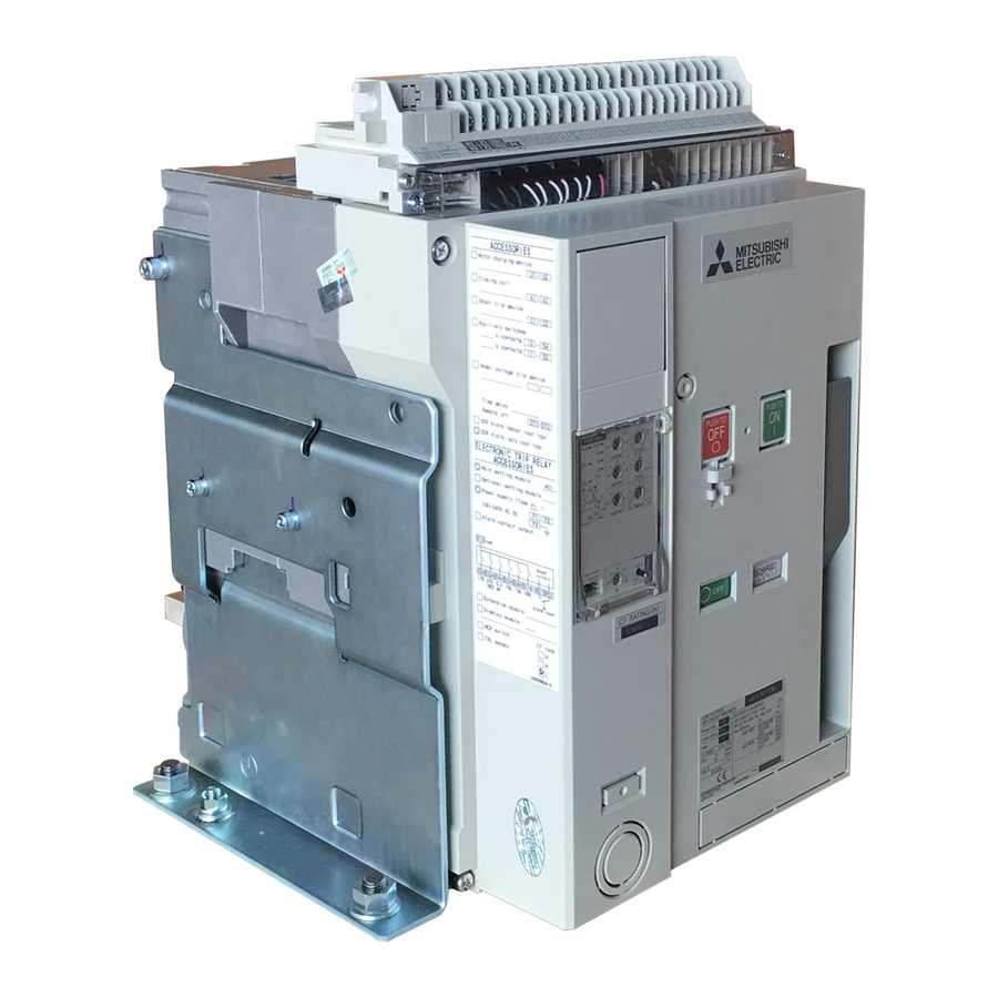
Internal construction Control circuit terminal block AE-SW Control circuit connector Auxiliary switch Shunt trip device, closing coil Electronic trip relay Front cover Tripping mechanism Closing mechanism Charging mechanism Closing spring Drawout mechanism Intermediate base Arc-extinguishing chamber Movable contact Fixed contact Conductor on the breaker Conductor on the cradle Main circuit junction... -
Page 5: Unpacking
Unpacking Make sure that the packing case is free from any abnormality such as breaking and/or wetting. Referring to the rating nameplate, make sure that the delivered breaker is in conformity with your order. Serial No. is indicated on the rated name plate and the cradle name plate (Fig. -
Page 6: Handling
Handling Fig. 6-1 Fig. 6-2 Never drop the breaker when Never roll the breaker handling. when handling. Wire length: 1 m or more Wire length: 1 m or more Lifting hooks (HP) CONNECT position Fig. 6-5 When lifting and placing, be careful nei- ther to drop nor to impact the breaker and the terminals for the center of gravity is Fixed type... -
Page 7: Installation
Installation < Drawout type > AE630-SW〜AE4000-SWA Tolerance on support flatness ≤ 1 mm Earthing terminal Fig. 7-1 Fig. 7-2 In the case of AE4000 ~ 6300-SW, insert four M12 bolts from the bottom and two M12 bolts from the back to mount the cradle as shown in Fig. -
Page 8: Mount Of Drawout Handle
Mount of drawout handle The drawout handle can be mounted on any of the left and right sides of the cradle. ¡Mounting on the left side ¡Mounting on the right side Drawout handle Handle holder Note: The drawout handle cannot be mounted on the left side of the cradle when the cradle is provided with a mechanical inter lock (MI) or a door inter lock (DI). -
Page 9: Connection
Connection ■Main circuit CAUTION CAUTION 25mm 40 ~ 50N·m Conductor Use small washers to connect that Fig. 9-1 the washers do not overlap with each other. Fig. 9-2 ACB termi- nal (silver- CAUTION plated) Fig. 9-3 Max. 200 mm Fixing support Fig. - Page 10 Table 10-1 Electromagnetic force in N per 1 m conductor (3-phase short circulation) Type AE630-SW AE2000-SW AE4000-SWA AE4000-SW AE2000-SWA Conductor distance (mm) Drawout type Fixed type Prospective fault current AE1600-SW AE3200-SW AE6300-SW kA (pf) 30 (0.2) 7,700 5,700 6,300 5,100 3,500 3,900 4,300...
-
Page 11: Insert Operation
Insert operation ■DISCONNECT → CONNECT position Release the lock levers, and pull the extension rails for- Place the breaker on the extension rails, using a lifter or ward. ropes. Mount the concave of the breaker in the rail pro- truding portion. (Fig. 11-5) Using a lifter or ropes Extension rails Lock levers... - Page 12 Push the lock plate in fully until it is latched to release After releasing the lock plate, turn the drawout handle the lock. clockwise. (Note:) (Note:) (a) If the lock plate is not fully released, turn the (a) Do not try to pull the unit out while inserting it as drawout handle to right and left a little.
-
Page 13: Drawout Operation
Drawout operation ■CONNECT → DISCONNECT position Remove two fixing bolts (M12) for the types AE4000 ~ 6300-SW. (See Fig. 13-1) Fig. 13-1 Keeping the OFF button pushed, insert the drawout handle. OFF button CONNECT position Push Fig. 13-2 (Prohibition) Do not insert the drawout handle unless the OFF Drawout handle button is pushed. - Page 14 When the breaker is drawn out to the test position, the drawout position indicator shows TEST position, and the lock plate automatically protrudes to lock the drawout handle. Automatic TEST position Fig. 14-1 Then, push in the lock plate, turn the drawout handle counterclockwise to change the displayed extraction position to the DISCONNECT position until the drawout position indicator shows disconnect position.
-
Page 15: Charging Operation
To drawout the breaker, pull each side equally. Otherwise (in the case of drawing slantwise) the breaker can not move smoothly. When ACB is installed at a high position, please do the Drawout / Insert operation by two people. (Note:) Since the center of gravity is by the terminal, the Cradle support is required to prevent from falling. -
Page 16: Opening/Closing Operation
Opening/Closing operation < Conditions of ON operation > ON operation will be possible, when all the following condi- tions have fulfilled. non-OFF instructions ¡The breaker is OFF condition. ¡The closing spring is charged. The charging indicator shows “CHARGED”. ¡The state without OFF operations. •... - Page 17 Electrical operation Control supply < Closing > Air circuit breaker CC Unit Remote closing can be made by emerging the closing coil (CC). Apply the rated voltage to the control terminals A1 , A2 , and Min. 80ms the breaker closes. The unit comprises an unti-pumping circuit which allows only Power supply One pulse...
-
Page 18: Door Interlock (Di)
Door interlock (DI) < Procedures for releasing door interlock > Even when the breaker is on, the interlock can be manually released. For this purpose, make a hole 7 or more in diameter in the panel door. (See the following figure.) (mm) Door Door hook... -
Page 19: Shutter Lock (Sst-Lock)
Shutter lock (SST-LOCK) The safety shutter can be locked at the closing position so that the live parts are not touched. Prepare a pad lock (5 in diameter) by yourself. Pad lock (f5) Shutter lock Fig. 19-1 Safety shutter name plate Please refer to a lower figure, if you need to attach the sticker “BUSBARS”... -
Page 20: Functions Of Electronic Trip Relay (Etr) Parts
Functions of electronic trip relay (ETR) parts 5 TAL LED and contact output < Functions > Option The ETR temperature detector is made functional by fit- 1 ERR. LED, Contact alarm output ting a TAL sensor. When any abnormality or setting failure is found in ETR, When the power type is P3 to P5, output is given between the LED alerts the operators to the abnormal status. - Page 21 < Pre-alarm function > < Load current LED > When the current exceeds pre-alarm current setting (lp), the The current value which is used as the reference of the load PAL LED will blink. When the LTD time (1/2 of T ) is passed, current indication LED, varies depending on the ETR types the PAL LED will light and output the contact.
-
Page 22: Characteristics Setting Of Type Ws Relay
Characteristics setting of type WS relay Pre-alarm current: Ip Uninterrupted current: Iu LTD time: T Pre-alarm time: Tp STD pick-up current: Isd With MCR STD time: Tsd t ON t OFF Max. breaking time INST Pick-up (In case of AE4000-SW~ current: Ii 6300-SW, it is 0.05s) Note: The figure includes the optional G1 ... -
Page 23: Characteristics Setting Of Type Wm Relay
Characteristics setting of type WM relay Pre-alarm current: Ip LTD pick-up current: I LTD time: T Pre-alarm time: Tp STD pick-up current: Isd STD time: Tsd With MCR t ON t OFF Max. breaking time INST Pick-up (In case of AE4000-SW~ current: Ii 6300-SW, it is 0.05s) Current (%) -
Page 24: Characteristics Setting Of Type Wb Relay
Characteristics setting of type WB relay Pre-alarm current: Ip Max. setting of let-through current Pre-alarm time: Tp Max. setting of external OCR INST pick-up current: Ii Up to Icw Up to Icw Max. breaking time (In case of AE4000-SW~ 6300-SW, it is 0.05s) Current (%) Note: The figure include MCR function. -
Page 25: Characteristic Setting Of Optional Setting Module
Characteristic setting of optional setting module < Characteristics setting of G1 module > Pick-up current: Ig 3.0±20% Operating time: Tg ¡When the 3pole breaker is used on a 3phase-4wires system, the neutral CT (NCT) is required for ground fault protection. As for the NCT installation, refer to instruction manual (included in the product). - Page 26 Characteristic setting of optional setting module < Characteristic setting of AP module > By combining with the Pre-alarm function already installed in standard ETR, the two step pre-alarm functions can be con- structed. In case of AE630-SW low rating type, the control supply is necessary for this function.
-
Page 27: Setting The Operation Characteristics
Setting the operation characteristics < Setting procedure > Before setting, turn off the breaker CAUTION and the ETR switch then make sure Note: Press the screwdriver in the direction of the arrow to open the cover. of no current conducting. Prepare a small flat tipped screwdriver. - Page 28 < Example for ETR characteristics setting > For setting calculation, take AE1600-SW 1600A WS1G1 relay for example. Current settings and operating times are calculated. = Rated current (CT rating) Ir=0.8 ✕ In Ii=12 ✕ Ir = Rated current setting =0.8 ✕ 1600A =12 ✕...
-
Page 29: Wiring Diagram
E − 29... -
Page 30: Technical Note (Arc Space, Reverse Connection)
Technical note ■ Arc space When the short circuit is interrupted, hot gas blows out discharged from the exhaust port of the arc-extinguishing cham- ber, so provide a clearance as shown in the following table. In case of drawout type, secure appropriate space to prevent the fingers from getting trapped at the time of drawing. Table 30 Dimensions (mm) Type... -
Page 31: Technical Note (Service Conditions)
Technical note ■ Service Conditions 2. Special service conditions 1. Normal service conditions In case of special service condition, service life may be- If under ordinary conditions the following normal working come shorter in some cases. conditions are all satisfied, the AE Series air circuit breaker 1Special environmental conditions may be used unless otherwise specified. -
Page 32: Inspection And Maintenance
Inspection and Maintenance 1. Guidelines for Inspection and Maintenance ..32 4. Inspection Details ........33 2. External view and Internal construction ..33 5. Fault Diagnosis ........36 3. Preparation before Inspection ....33 The maintenance and inspection frequency and content are different depending on the working conditions. Read through the following for details of sufficient maintenance and inspection requirements. - Page 33 2. External view and Internal construction Please refer to page 3 and 4 of this manual. 3. Preparation before Inspection For routine inspection under normal service conditions, proceed with the following. Make sure that the circuit breaker is turned OFF. CAUTION Do not drawout the circuit breaker when...
- Page 34 4.2 Periodic Inspections It is recommended that periodic inspections are performed once about one month commencing use thereafter according to the guidelines for inspection and renewal to ensure a stable, long-term use of the ACB. 4.2.1 External appearance of the ACB Inspection item Inspection method Criteria...
- Page 35 4.2.5 Accessory devices (General accessory devices) Inspection item Inspection method Criteria Treatment methods 1.Closing coil (CC) Electrical operation Must operate reliably and without difficulty Please contact our company if there are any Shunt trip device (SHT) within the operating voltage range indicated in abnormalities.
- Page 36 5. Fault Diagnosis Treatment Type and condition Defect/Probable cause of abnormality Investigation/Primary treatment Secondary treatment 1.Cannot close. 1.The closing operation cannot be performed. (1) The OFF-lock device (CYL,CAL,Padlock) Release the OFF-lock device. Please contact our company if closing is not released. (CYL,CAL,Padlock) cannot be performed even after completing (2) The drawout position is not appropriate.
- Page 37 Treatment Type and condition Defect/Probable cause of abnormality Investigation/Primary treatment Secondary treatment 6.Abnormality Electron- ic Trip Relay (ETR) (1)Trip unnecessarily 1.Tripped at rated current or less Check the load current and characteristics Please contact our company if there are any setting of the ETR.
-
Page 38: Service Network
Vte. Agua Santa 4211 Casilla 30-D (P.O. Box) Vina del Mar, Chile +56-32-2-320-600 Mitsubishi Electric Automation (China) Ltd. Mitsubishi Electric Automation Building, No.1386 Hongqiao Road, Shanghai, 200336 +86-21-2322-3030 Mitsubishi Electric Automation (China) Ltd. 9/F, Office Tower1 Henderson Centre 18 Jianguomennei... - Page 39 According to Registration of Broadcasting and Communication Equipments belonging in “KC”, we inform of the following user guidance. Applicable models are Electronic type of ACBs, MCCBs and ELCBs. E − 39...
- Page 40 三菱低圧気中遮断器 World Super AE 形 MITSUBISHI Low-Voltage Air Circuit Breakers World Super AE Type AE-SW 東京都千代田区丸の内2-7-3 ( 東京ビル) Á100-8310 HEAD OFFICE: TOKYO BLDG., MARUNOUCHI, 2-7-3, CHIYODAKU, TOKYO 100-8310. TELEX: J24532 CABLE: MELCO TOKYO 三菱電機株式会社 福山製作所 Á720-8647 広島県福山市緑町1番8号 TEL (084)921-3211 FAX (084)931-4714 MITSUBISHI ELECTRIC FUKUYAMA WORKS...
- Page 41 AE-SW AE630-SW AE1000-SW AE1250-SW AE1600-SW AE2000-SWA AE2000-SW AE2500-SW AE3200-SW AE4000-SWA AE4000-SW AE5000-SW AE6300-SW...
- Page 42 ¡ ¡ ¡ ¡ ¡ ¡ ¡ ¡ ¡ ¡ ¡ ¡ ¡ ¡...
- Page 43 ¡ ¡ ¡ ¡ ¡ ¡ ¡ ¡ ¡ ¡ ¡ ¡ ¡ ¡ ¡ ¡ ¡ ¡ ¡ ¡ ¡ ¡ ¡ ¡ ¡ ¡ ¡ ¡ ¡ ¡ 固定螺栓...
- Page 44 ¡ ¡...
- Page 47 ≤...
- Page 48 ¡ ¡...
- Page 49 ¡...
- Page 50 ✕ ✕ ✕ ✕ ✕ ✕ ✕ ✕ ✕...
- Page 55 ¡ ¡ ¡ 〜 〜 ...
- Page 56 ¡ ¡ ¡ • • •...
- Page 57 OUT3 OUT4...
- Page 60 • • • Do not...
- Page 61 OVER OVER Ω Ω Ω Ω...
- Page 63 在 在...
- Page 65 ¡ ¡ Δ ± ¡ ¡ ± Δ Δ...
- Page 67 INST Do not l i (xlr)...
- Page 68 —...
- Page 71 ≤ ≤ ≤...
- Page 72 ¡ ¡ ...
- Page 80 MITSUBISHI Low-Voltage Air Circuit Breakers World Super AE 三菱低圧気中遮断器 World Super AE Type AE-SW 東京都千代田区丸の内 2-7-3(東京ビル)Á100-8310 HEAD OFFICE: TOKYO BLDG., MARUNOUCHI, 2-7-3, CHIYODAKU, TOKYO 100-8310. TELEX: J24532 CABLE: MELCO TO KYO 三菱電機株式会社 福山製作所 Á720-8647 広島県福山市緑町 1 番 8 号 TEL (084)921-3211 FAX (084)931-4714 MITSUBISHI ELECTRIC FUKUYAMA WORKS...
- Page 81 三菱低圧気中遮断器 World Super AE 形名 AE-SW 取扱説明書 〈対象機種〉 AE630-SW AE1000-SW AE1250-SW AE1600-SW AE2000-SWA AE2000-SW AE2500-SW AE3200-SW AE4000-SWA AE4000-SW AE5000-SW AE6300-SW ご使用の前に必ずこの取扱説明書をお読みください。 この説明書は、最終ユーザまでお届けください。...
-
Page 82: 安全上のご注意
安全上のご注意 ●ご使用の前に、この 「取扱説明書」 をお読みの上、正しくお使いください。 安全に関する重大な内容を記載していますので、必ず守ってください。 ●この 「取扱説明書」 は、最終使用者まで必ずお届けください。 ●この 「取扱説明書」 は、電気に関する専門知識を有する人を対象としています。 表示と意味は次のようになっています。 取扱を誤った場合に、危険な状況が 取扱を誤った場合に、危険な状況が 起こりえて、中程度の障害や軽傷を 危 険 注 意 起こりえて、死亡または重傷を受け 受ける可能性が想定される場合およ る可能性が想定される場合。 び物的損害だけの発生が想定される 場合。 特定の条件において、感電の可能性を注意す 禁止を意味するので、絶対にしないでくださ る。 い。 特定の条件において発火、火災の可能性を注 必ず指示にしたがって行なってください。 意する。 危 険 ●定格を超えた条件では、使用しないでください。絶縁破壊による地絡・短絡事故や遮断不能による爆発などのおそれがあります。 ●端子部に触れないでください。感電のおそれがあります。 注 意 ●電気工事は、有資格者(電気工事士)が行ってください。... - Page 83 もくじ ●安全上のご注意 …………………………………… 2 ●シャッターロック (SST-LOCK)……………… 19 ●外観 ………………………………………………… 3 ●安全シャッター名板 …………………………… 19 ●内部構造 …………………………………………… 4 ●引きはずしリレー (ETR) 各部の機能 ………… 20 ●製品寸法と製品質量 ……………………………… 4 ●WSタイプの特性設定 …………………………… 22 ●開梱 ………………………………………………… 5 ●WMタイプの特性設定 ………………………… 23 ●保管 ………………………………………………… 5 ●WBタイプの特性設定 …………………………… 24 ●運搬 ………………………………………………… 6 ●オプション設定モジュールの特性設定...
-
Page 84: 内部構造
内部構造 1制御回路端子台 AE-SW 2制御回路コネクタ 3補助スイッチ 4電圧引きはずし装置、投入コイル 5引きはずしリレー 6カバー 7引きはずし機構 8投入機構 9チャージ機構 A投入ばね B引出機構 C中間ベース D消弧室 E可動側主接点 F固定側主接点 G本体側導体 H引出枠側導体 I主回路ジャンクション Jベース K接圧用ばね L本体側導体 M引出枠側導体 N電源CT 図4-1 O電流検出コイル P引出枠 Q引出枠名板 製品寸法と製品質量 表4-1 ●固定形 形名 AE630-SW AE1000-SW AE1250-SW AE1600-SW AE2000-SWA 3P 340×410×290×40 340×410×290×108 ... - Page 85 開 梱 1 梱包ケ−スが破損・水ぬれ等、異常のないことを確認してください。 2 遮断器本体の名板により、ご発注どおりであることを確認してください。 製造番号は、定格名板と引出枠名板 (図4-1Q) に表示しています。 固定形 引出形 付属名板 ETR 付属名板 ※同梱は されていません 図5-1 図5-2 図5-3 CT 定格名板 定格名板 図5-4 保 管 ※保管後、使用開始するときに保管期間が6年を超える場合は、注油後ご使用ください。注油につきましては当社サービス部門へお問 合せください。 +60℃ −20℃ 1日の平均気温 相対湿度85%以下 35℃以下 図5-5 図5-6 図5-7 S≦0.01ppm ≦0.05ppm ≦0.25ppm 図5-10 図5-8 図5-9 図5-11 J − 5...
- Page 86 運 搬 図6-1 図6-2 地面に降ろすときに落とさない 開梱前に転がして運搬し こと。 ないこと。 ワイヤー長さ1m以上 ワイヤー長さ1m以上 吊下げ金具 (HP) CONNECT (接続) 位置 図6-5 遮断器を吊り下げる場合、重心位置が端子 部にあるため、着地する時に遮断器及び端 子部に衝撃を加えないよう注意してくださ 固定形 引出形 い。 図6-3 図6-4 引出形を引出枠付きで運搬する 場合は、CONNECT (接続) 位 置で吊り下げてください。 1m以上 図6-6 引出形遮断器を運搬する場合、1m以上の ロープ4本または専用のリフタを必ずお使 いください。 J − 6...
-
Page 87: 取付け
取付け 〈引出形〉 AE630-SW〜AE4000-SWA 取付け面の平面度≦1mm ア−ス端子 図7-1 図7-2 AE4000〜6300-SWの場合は、図7-3のようにM12のボルト (4本) を下から、M12のボルト (2本) を背部から挿入し、 引出枠を取付けてください。4極品 (FN) の場合は、図7-4のようにM12のボルト (6本) を下から、M12のボルト (2本) を背 部から挿入し、引出枠を取付けてください。 AE4000〜6300-SW 3P & 4P (HN) AE4000〜6300-SW 4P (FN) 引出枠 取付アングル (非磁性材) 取付アングル (非磁性材) 2-M12 2-M12 6-M12 4-M12 図7-3 図7-4 引出操作 (接続⇒引出) の指示に従い引出操作を行なってください。 (P.13,14参照) 注 意 注... -
Page 88: 引出ハンドルの取付
引出ハンドルの取付 引出ハンドルは、引出枠側面の左右どちらにでも、取付けることができます。 ●左側取付けの場合 ●右側取付けの場合 引出ハンドル 引出ハンドル取付具 注) メカニカルインターロック(MI)または、ド アインターロック(DI)付の場合は、引出ハ ンドルを引出枠右側に装着できません。 盤内の適切な場所に取付けください。 メ カニカルイ ンターロ ッ ク (MI) または、 ドアイ ンターロ ッ ク (DI) 引出枠 ナット M5 図8-1 図8-2 取付ねじ M5×12 2.8〜3.6 N・m 図8-3 相間バリヤの取付 矢印に沿って、溝に挿入してください。 〈固定形〉 〈引出形〉 図8-4 図8-5 J − 8... - Page 89 接 続 ■主回路 注 意 注 意 25mm 40〜50N・m 導帯 座金は重ならないように小座金を使 図9-1 用し接続してください。 図9-2 ACB端子 (銀メッキ) 注 意 図9-3 最大 200mm 固定用サポ−ト 図9-4 ■制御回路 過大なトルクで締付けると端子、ねじ が破壊する恐れがありますので、規定 ●圧着端子サイズ トルクで締め付けてください。 十字穴 (すりわり) に径のあったドライ 1.25mm 〜2.0mm 電線にて バーを使ってください。 推奨圧着端子 ドライバーサイズ (H形, フィリプス) N2-M3(RAP2-3.5) (JST) M3.5 ・・・・・・・・・・・・・・・・・・・...
- Page 90 表10-1 導帯1mあたりに働く電磁力 (三相短絡の場合) (N) 形名 AE630-SW AE2000-SW AE4000-SWA AE4000-SW AE2000-SWA 〜 引出形 固定形 〜 導帯間隔(mm) 〜 3P 4P AE3200-SW 3P 4P 3P 4P AE6300-SW 推定電流対称値 AE1600-SW kA(pf) 85 115 105 130 190 170 152 145 262 30 (0.2) 7,700 5,700 6,300 5,100 3,500 ...
-
Page 91: 挿入操作
挿入操作 ■引出位置 → 接続位置 1 ロックレバーを手前に引き、引出枠とロックレバーの係合を 2 リフターまたは専用吊下げ金具で吊下げて遮断器をレールの はずして、引出レールを前方に引出します。 上に乗せます。レール突起部へ遮断器凹部をはめ込んでくだ さい。 (図11-5) リフターまたは吊下げ金具使用 引出レール ロックレバー 図11-1 図11-2 3 遮断器をゆっくりと動かなくなるまで押し込んでください。 遮断器を挿入する時は、均等に挿入してください。 注 意 均等でない場合 (本体が斜めに押し込まれた場合) 、本体がス ムーズに入りません。 遮断器凹部 高い場所にACBが据付けられている場合は、2人で行なって ください。 レール凸部 落下 図11-5 引出枠が固定されていない状態で 遮断器本体をレールの上に乗せる カチッ! と重心が手前に移動するため転倒 防止を行なってください。 図11-4 図11-3 注... - Page 92 5 ロックプレートをラッチに掛かるまで押し込んでロックを解 6 ロックを解除しロックプレートから手を離して、引出ハンド 除してください。 ルを時計方向に回転させてください。 (注意) (注意) (a)ロックプレートの解除操作が重い場合、引出ハンドル (a)挿入操作の途中で、引出操作をしないでください。位 を左右に少し回転させてください。 置表示が正確に動作しないことがあります。この場合 (b)ロックプレートは必ず解除位置まで押し込んでくださ は一度本体を断路位置まで引き出して再度挿入操作を い。位置表示が正確に動作しないことがあります。 してください。 ロックプレート ロック位置 押す カバー ラッチ 解除位置 図12-1 図12-2 7 試験位置まで遮断器が挿入されると引出位置表示がTEST(試 8 次に、ロックプレートを押し込んで、ハンドルを時計方向に 験)位置を示し、ロックプレートが自動的に突出して引出ハン 回転させます。接続位置まで遮断器が挿入されるとロックプ ドルの回転がロックされます。 レートが自動的に突出して挿入操作が完了します。このとき 引出位置表示はCONNECT(接続)位置を示します。 注 意 必ずロックプレートが突出するまで挿入操作をおこなって ください。突出していなければ不完全な接続の可能性があ ります。 (注意) (a)挿入完了後、引出ハンドルの回転操作はしないでくだ...
-
Page 93: 引出操作
引出操作 ■接続位置 → 引出位置 1 AE4000〜6300-SWの場合は、両サイドの2本の引出枠 と本体固定用ボルト (M 1 2 ネジ) を取外してください。 (図13-1) 図13-1 2 OFFボタンを押した状態で、引出ハンドルを挿入してください。 OFFボタ ン CONNECT (接続) 位置 押す 図13-2 (禁止) OFFボタンを押さずに、引出ハンドルを挿入しないでく ださい。 引出ハン ドル 図13-3 3 ロックプレートをラッチに掛かるまで押し込んでロックを解 除してください。 ロ ッ クプレー ト (注意) ロ ッ ク位置 押す (a)ロックプレートの解除操作が重い場合、引出ハンドル を左右に少し回転させてください。... - Page 94 5 遮断器が試験位置まで引出されると引出位置表示がTEST(試 験)位置を示し、ロックプレートが自動的に突出して引出ハン ドルの回転がロックされます。 自動 TEST (試験) 位置 図14-1 6 次に、ロックプレートを押し込んで、ハンドルを反時計方向 に回転すると引出位置表示がDISCONNECT(断路)位置とな り、さらに遮断器本体が動かなくなるまで操作を行なってく ださい。これで引出操作は完了です。 遮断器は手で引出すことができます。 (注意) (a)DISCONNECT (断路) 位置になる前にロックプレート が突出することがあります。その場合、ロックプレー トを押し込み、解除状態にしてハンドル操作を続けて ください。 (b)ロックプレートの解除操作が重い場合、引出ハンドル を左右に少し回転させてください。 (c)断路位置では引出ハンドルが空回りし、ロックプレ− トの突出はありません。 DISCONNECT (断路) 位置 図14-2 7 遮断器本体を引出枠から外す場合はロックレバーを手前に引 き、係合をはずして引出レールを手前に引出して、遮断器を 引出してください。 注 意 注 意 ロ...
-
Page 95: チャージ操作
8 遮断器を引出す時は、均等に引出してください。 均等でない場合 (本体が斜めに出た場合) 、本体がスムーズに 出ません。 高い場所にACBが据付けられている場合は、2人で行なって ください。 (注意) 引出枠の重心が端子部にあるため支持物を設置して転倒、 落下防止を行なってください (図15-1) 。 図15-1 チャージ操作 〈手動チャージ〉 投入バネのチャージ操作を手動で行ないます。 チャージハンドルを下側へ全ストロ−クで7〜8回行ない、ハン ドルがフリーになるまで操作すると、投入バネがチャージされ チャージ完了となります。このとき、チャージ状態表示は、 CHARGED (チャージ完了) を表示します。 操作荷重は30N・m以下です。 チャージ操作 7〜8回 図15-2 〈電動チャージ〉 表15-1 電動チャージ定格 使用電圧 突入電流 必要電源 投入バネのチャージ操作を電気的に行ないます。 定格電圧 操作電圧 定常電流 チャージ 範囲 (波高値) 容量 遮断器が投入... -
Page 96: 開閉操作
開閉操作 〈投入操作可能条件〉 以下の条件が成立するとON操作可能になります。 指令がない 開放 ●遮断器がOFF状態 ●投入ばねがチャ−ジ完了状態「CHARGED」 ●開放指令がない状態 (下記条件) ・ SHTに電圧が印加されていない ・ MIやCYLによる機械的ロックがない ・ UVTに電圧印加されており、トリップ操作状態ではない 図16-1 手動開閉操作 〈投入〉 ONボタンを押すと遮断器は投入され、ON/OFF状態表示窓は 「ON」を表示し、チャ−ジ状態表示窓は「DISCHARGED」を表 示します。 操作荷重は50N以下です。 (注意) OFFロック装置 (パッドロック、シリンダーロック、カ ステルロックなど) を使用している時は、ロック状態を 解除の後 投入操作を行なってください。 引出形遮断器の場合、CONNECTまたはTEST位置で 開閉させるときはロックプレートが突出している状態 図16-2 にて開閉してください。 不足電圧引きはずし装置 (UVT) がついている場合は、 定格電圧を印加して投入してください。 〈開放〉 OFFボタンを押すと遮断器は開放され、ON/OFF状態表示窓は 「OFF」を表示します。 操作荷重は50N以下です。 図16-3 J −... - Page 97 電気開閉操作 CC回路図 〈投入〉 投入コイル(CC)を使用すれば電気的に投入操作ができます。制 気中遮断器 CCユニッ ト 最小80ms 御回路端子台の A1 , A2 に定格電圧を印加することで、遮断 器を投入できます。 1回の投入指令で1回の動作しか行なわないポンピング防止回路 電源 パルス を内蔵しています。 発生回路 再投入する場合は、一度投入コイルの電源( A1 - A2 間)をOFF にした後、再度定格電圧を印加してください。 不足電圧引きはずし装置 (UVT) 付の場合、電源印加をしないと 投入できません。 (UVTに電源印加後投入可能となるまで1.5秒 注) DC24-48V品には整流回路はあ り ません。 の待ち時間が必要です。) 図17-1 〈開放〉 電圧引きはずし装置(SHT)または、不足電圧引きはずし装置 SHT回路図 (UVT)を使用すれば電気的に開放操作ができます。 SHTの場合は、制御回路端子台の C1 , C2 に定格電圧を印加 してください。 気中遮断器 焼損防止スイ ッ チ UVTの場合は、制御回路端子台のトリップ用端子 DT1 , DT2 SHTユニッ...
-
Page 98: ドアインターロック (Di
ドアインターロック (DI) 〈ドアインターロックの解除方法〉 1 遮断器がONの状態でも手動でインターロックの解除が可能です。 この場合盤扉にφ7以上の穴を空けてください。 (下図参照) (mm) ドア ドアフック A方向 解除 (5) 解除用穴φ7以上 遮断器オン A方向から見る 図18-1 シリンダーロック (CYL) ・カステルロック (CAL) 〈OFF ロック方法〉 〈解除方法〉 1 OFFボタンを押してACBをOFFします。 1 キーを差し込んで解除側へキーを回転させてください。 キーが回りにくいときはOFFボタンを押し込んだ状態でキー 2 OFFボタンを押したままキーをロック側へ回転するとキーが を解除側へ回転させてください。 ぬけてOFF ロックできます。 ロ ッ ク 図18-3 図18-4 図18-2 解除 J − 18... -
Page 99: シャッターロック (Sst-Lock
シャッターロック (SST-LOCK) 充電部に触れないように、安全シャッターを閉位置でロックす ることができます。 南京錠 (φ5) はお客様でご用意ください。 パッ ドロ ッ ク (φ5) シ ャ ッ ターロ ッ ク 図19-1 安全シャッター名板 安全シャッターに同梱の名板 「BUSBARS」 , 「CABLES」 をご使用の場合は、下記貼付け例を参照ください。 同梱名板 同梱名板 図19-2 J − 19... -
Page 100: 引きはずしリレー (Etr) 各部の機能
引きはずしリレー (ETR) 各部の機能 5TAL LED,接点出力 オプション 〈各部の機能説明〉 ETRの温度検出 は TAL センサが装着されることで機能しま 1ERR. LED,接点出力 す。電源タイプP3〜P5の場合、制御回路端子台 ETRに何らかの異常または設定間違いがある場合、異常状態 間に出力します。温度が下がれば、出力はRESETされますの を知らせます。電源タイプP3〜P5の場合、制御回路端子台 で保持のためには外部シーケンスにて対応ください。 間に接点出力します。 ・ETRの機能異常 (マイコン,H/W) 6MCR(Making current release) オプション ・設定間違い (Inst/MCR設定間違い) 遮断器投入時(OFFからON)のみ、INST特性を有し、投入後 ・ETR関連ACB内部配線異常 はINSTは無くなります。発注時MCRを指定いただくと、本 2RUN LED (ETR) 体内にMCRスイッチが内蔵され、ETRはMCR,INST切替式 ETR が機能状態にあることを表示します。制御電源が印加さ となります。 (図20-2) れているか、主回路に約10%の電流が流れると内部回路が起 7リセットボタン 動し、点灯します。 ETR前面の"RESET"ボタンを操作するか、制御回路端子台 3RUN LED (オプション設定モジュール) 間をショートすることで、トリップ原因表示 オプション設定モジュールが機能状態にあることを表示します。... - Page 101 〈負荷電流表示LED〉 〈プレアラーム動作〉 負荷電流表示LEDの基準となる電流値は、特性の設定に対応して プレアラーム電流設定 (Ip) を越えるとPAL LEDが点滅し、長限 変わります。 時動作時間 (T ) の1/2を経過すると点灯し、接点出力します。 動作時間は特性曲線を参照してください。 表21-1 電流 LED表示の 用途区分 リ レータイ プ LED表示 基準となる電流 負荷電流 OVER WS 点灯 PAL LED 100 WS1 Iu 点滅 一般保護用 80 WS2 連続通電電流 PAL接点出力 60 1/2 T 経過時間 t 100 WM 80 ...
-
Page 102: Wsタイプの特性設定
WSタイプの特性設定 プレアラーム 電流 : Ip 連続通電電流 : Iu 長限時 動作時間 : T プレアラーム 動作時間 : Tp 短限時電流 : Isd MCR付の場合 短限時 動作時間 : Tsd t ON t OFF 最大遮断時間 瞬時電流 : Ii (AE4000-SW〜6300-SW の場合は0.05s) 注) 図はオプシ ョ ンG1設定モジュール、 ディ スプレイ、 電流... -
Page 103: Wmタイプの特性設定
WMタイプの特性設定 プレアラーム電流 : Ip 長限時電流 : I 長限時 動作時間 : T プレアラーム 動作時間 : Tp 短限時電流 : Isd 短限時 動作時間 : Tsd MCR付の場合 I t ON t OFF 最大遮断時間 (AE4000-SW〜6300-SW 瞬時電流 : Ii の場合は0.05s) 電流 (%) 注) 図はオプシ ョ ンG1設定モジュール、 ディ スプレイ、 MCRを含んだものです。... -
Page 104: Wbタイプの特性設定
WBタイプの特性設定 プレアラーム 電流 : Ip 最大通電可能時間 プレアラーム 動作時間 : Tp 外部OCRの 最大設定値 瞬時電流 : Ii 最大Icwまで 最大Icwまで 最大遮断時間 (AE4000-SW〜6300-SW の場合は0.05s) 電流 (%) 注) 図は、 オプシ ョ ンのMCRを含んだものです。 表24 工場出荷時 No. 設定項目 記号 特性設定範囲 精度 ... -
Page 105: オプション設定モジュールの特性設定
オプション設定モジュールの特性設定 〈G1 モジュールの特性設定〉 地絡電流 : Ig 3.0±20% 地絡動作時間: Tg ●3極品で三相4線の地絡保護を行なう場合はN極CT (NCT) が必要です。 仕様についてはカタログを参照ください。 0.15±20% NCTの据え付けについては、 NCTに同梱の取扱説明書を参照ください。 <0.1 ●AE630-SWの低定格品 (CT Rating : 500A, 315A, 250A) には (0.04〜0.1s) G1モジュールを取付けできません。 表25-1 地絡電流 (CT定格Inに対する%) No. 設定項目 記号 特性設定範囲 精度 工場出荷時設定値 ① 地絡電流 Ig 0.1〜1.0×In (0.1ステ ッ プ) ±20% ... - Page 106 オプション設定モジュールの特性設定 〈APモジュールの特性設定〉 標準装備のプレアラーム機能との併用により、2段プレアラーム を構成することができます。 なお、AE630-SW低定格品については、必ず制御電源を印加く ださい。 ●WSタイ プの場合 ●WMタイ プの場合 2ndプレアラーム 2ndプレアラーム 電流 : Ip2 電流 : Ip2 長限時動作時間 : T L 12-25-50-100-150s ( at Iu×2) 長限時動作時間 : T L 15-20-25-30-40-60s ( at I ×1.2) 2ndプレアラーム 2ndプレアラーム 動作時間 : Tp2 (FLAT) 動作時間...
-
Page 107: 引きはずし特性の設定方法
引きはずし特性の設定方法 〈設定操作手順〉 設定の変更は、遮断器の主電源とETRの 注 意 制御電源をOFFにして、通電していない 注) 矢印の方向へドライバーを押し、開けてください。 ことを確認しておこなってください。 1 小型のマイナスドライバーをご用意ください。 6mm以下 0.8mm以下 先端部側面 2 ETR (Electronic trip relay) カバーの上部開口部に、マイナ スドライバーを差込み、図27-1のように軽く上方向へ押す と、ETRカバーが開きます。 3 スイッチには、下記の2種類があります。それぞれの方法で 操作ください。 (a)ステップ式 ステップ式ロータリースイッチです。中間位置で止めない でください。目盛りが連続した太線部では、同一設定とな ります。 (操作トルク0.02N・m以下) 中間位置に止めた場合は、 その両側のどちらかの特性 値となります。 封印穴 ETRカバー MCR (オプション) がないとき、Iiの設定は INST 左図のようになっています。矢印の D o Do not ... - Page 108 〈引きはずしリレー設定例〉 設定値の計算について、AE1600-SW 1600A WS1G1リレーを例にとって説明します。 各設定電流、動作時間を計算します。 In =定格電流 (CT定格) Ir=0.8×In Ii=12×Ir Ir =定格電流設定 =0.8×1600A =12×1280A Iu =連続通電電流 (非遮断電流) =1280A =15360A =長限時動作時間 Isd =短限時電流 Tsd =短限時動作時間 Ii =瞬時電流 =100秒 Iu=0.9×Ir Ip =プレアラーム電流 Iuの2倍の電流 =0.9×1280A Ig =地絡電流 =1152×2=2304Aに =1152A =地絡動作時間 おける動作時間 Tsd=0.3秒 Isd=3×Ir ...
-
Page 109: 結線図
J − 29... -
Page 110: 技術資料 (アークスペース、逆接続
技術資料 ■アークスペース 短絡電流を遮断した時、消弧室の排気孔からホットガスが噴出されますので右表の空隙を設けてください。 引出形の場合、引出操作時の指つめ防止のため適切な寸法を確保してください。 表30 寸法変化表 (mm) 形名 AE630-SW〜AE4000-SWA AE4000-SW〜AE6300-SW 電気機器、 器具およびス ク リ−ン AC660V 使用回路電圧 ≦AC600V ≦AC690V AC690V A (注1) 0 (注1) 100 (注1) 200 B (注3) 50 (注3) 50 (注3) 50 固定形 C 162 162 ー D ... -
Page 111: 技術資料 (使用環境
技術資料 ■使用環境 1.標準使用環境 2.特殊使用環境 次の使用条件をすべて満足する場合を標準使用環境とし、特 標準使用環境以外でご使用になる場合には、標準使用環境条 にご指定がない場合、AE形気中遮断器はこの環境でご使用く 件下に比べ期待寿命が短くなる場合があります。 ださい。 ①特殊環境条件 ①標準使用周囲温度 高温、多湿な環境で使用される場合。 最高+40℃、最低−5℃の範囲でご使用ください。但し、 腐食性ガスの発生する環境で使用される場合。 24時間の平均値は+35℃を超えないこと。 ②特殊周囲温度 ②標高: 2000m (6600フィ−ト) 以下。 周囲温度が+40℃を超える場合は、「連続通電」電流が低減 ③環境条件 されます。 空気は清浄で最大温度+40℃において相対湿度は85%以 ③特殊標高 下。 2000mを超える標高で使用される場合は、熱の放散が低 硫化ガス・アンモニアガスなどの腐食性ガス雰囲気内で使 下するため、使用電圧、通電容量および遮断容量が低減さ 用、保管放置しないでください。 れます。また、絶縁耐力も気圧により低減されます。詳細 ( H S≦0.01ppm, SO ≦0.05ppm, NH ≦0.25ppm) はご照会ください。 ④取付け条件 AE形気中遮断器は、カタログ、取扱説明書の取扱い指示に 従って取り付けてください。 ⑤更新の目安 標準使用環境での期待寿命は約15年です。 更新時期は使用環境により左右されます。この取扱説明書 の点検・保守のページを参照してください。 保証について... -
Page 112: 点検・保守
点検・保守 1.点検、更新の目安 ……………………………… 32 4.点検について …………………………………… 33 2.外観、構造 ……………………………………… 33 5.異常現象に対する処置方法 …………………… 36 3.点検前の準備 …………………………………… 33 点検・保守の項目と必要頻度は使用条件により異なりますが、マニュアルの内容を熟読の上、十分な点検・保守を行ってください。 注 意 ●点検・保守は、専門知識を有する人が行ってください。 感電のおそれがあります。 ●点検・保守は、上位遮断器を切(OFF)し、電気がきていないことを確認して行ってください。 感電のおそれがあります。 やむを得ず電源を切らないで行う場合はゴム手袋をはめゴムマットを床にしき絶縁された靴をはき、絶縁された工具を使って行っ てください。このとき充電部に近づくことになりますので人体と充電部との絶縁には充分ご注意ください。 なお通常の開閉などの操作部はモールド部材で充電部から絶縁されており安全です。 1. 点検、更新の目安 〈目的〉 点検:遮断器の点検の目的は異常個所の早期発見、消耗劣化部品の適時更新により遮断器の性能維持と寿命による事故を未然に防ぐこ とにあります。 保守:遮断器の性能を維持するために、注油など定期的な保守が必要となりますので、当社サービス部門へお問合せください。期間 (点 検周期) は定期点検2回に1回の割合で行なってください。 1.1 使用期間、使用環境による定期点検・保守と更新の目安 初期点検は使用開始後1ヶ月後に1回、その後は使用環境に応じて定期点検を行なってください。 使用環境 具体例 点検の目安 ... - Page 113 2. 外観、構造 この取扱説明書の3ページ、4ページをご参照ください。 3. 点検前の準備 通常の点検 (初期点検、定期点検) は、上位遮断器を開放 (OFF) し、電気がきていないことを確認のうえ実施してください。ま た、制御回路については、動作確認時を除き、できるだけ電源 を切断のうえ実施してください。 注 意 遮断器がO N の場合に は遮断器を開放 (OFF) して引出操作をしてく ださい。 (13ページ参照) 4. 点検について 4.1 初期点検 4.1.1 点検項目 気中遮断器を組み込んだ後、通電を開始する前に次の項目について点検を実施してください。 点検項目 判定基準 判定基準 1.主回路接続端子への電線、 導帯が確実に締付け られているか 規定の締付 トルク (M12ネジ : 40〜50N・m) で締付けてあるこ と 2.端子まわりに、...
- Page 114 4.2 定期点検 事故を未然に防ぎ気中遮断器を長期間安定して使用していただくために、使用開始後1ヶ月前後に1回その後は環境に応じて定期点 検されることを推奨いたします。 4.2.1気中遮断器外観 点検項目 点検方法 判断基準 処理方法 1.塵埃や汚れ 目視 塵埃や汚れの付着のないこ と 定期点検毎に掃除機で吸い取るか、 乾いた布で 除塵及び清掃する フロン トカバー、 名板類はシンナー等の溶剤使用 は不可 2.主回路端子接続部の緩み トルク レンチで締付ける 確実に締ま っているこ と 必要な ら増締めする (M12ネジ : 40〜50N・m) 3.制御端子接続部の緩み ドライバーで締付ける 確実に締ま っているこ と 必要な ら増締めする (M3.5ネジ : 0.8〜1.2N・m) 4.フロン...
- Page 115 4.2.5 付属装置 (一般的な付属装置について) 点検項目 点検方法 判断基準 処理方法 1.投入コイル (CC) 電気操作 定格電圧範囲内で支障な く確実に動作す 動作異常の時は当社へ連絡願います 電圧引きはず しコイル (SHT) るこ と 2.補助スイ ッ チ (AX) AXa、 AXbの導通確認 遮断器の開閉に応じて確実に切換るこ と 動作異常の時は当社へ連絡願います 3.電動チャージ装置 (MD) 電気操作 「取扱説明書」 記載の使用電圧範囲内で 動作異常の時は当社へ連絡願います 規定時間 (5秒以内) に確実にチャージを 完了するこ...
- Page 116 5. 異常現象に対する処置方法 処置 異常の種類、 状態 不具合現象/推定原因 調査/一次処置 二次処置 1.投入不能 1.投入動作を しない (1) OFFロ ッ ク装置 (CYL、 CAL、 パッ ドロ ッ ク) OFFロッ ク装置 (CYL、 CAL、 パッ ドロッ ク) を解 一次処置を実施しても投入できない場合は当社 が解除さ れていない 除する に連絡願います (2) 引出位置が適正でない 「断路位置」 、 「試験位置」 、 「接続位置」 のい ずれかにする ...
- Page 117 処置 異常の種類、 状態 不具合現象/推定原因 調査/一次処置 二次処置 6.引きはず し リ レー (ETR) (1) 不要 ト リ ッ プする 1.通常負荷で不要 ト リ ッ プする 負荷電流とETR設定値を確認し、 設定が正しい 特性に異常のある と きは当社に連絡願います かど う か確認する フ ィ ール ドテス ト装置で引きはず し特性をチェ ッ クする 2.負荷始動時に不要...
-
Page 118: 遮断器Fax技術サービスご照会用紙
発信総枚数 枚 遮断器 技術サービス 年 月 日 送信先 FAX No. 084-926-8280 対象機種:ノーヒューズ遮断器 ・ 漏電遮断器 ・ リモコン機器 低圧気中遮断器 ・ サーキ ッ トプロテクタ他 三菱電機株式会社 福山製作所 遮断器FAXサービス行 発信元(ご照会元) 会社名 住所 所 属 (フリガナ) 様 お名前 FAX No. 受付時間:9:00〜16:00 (土 ・ 日曜および祝 ・ 休日除く) お取引代理店および担当者 ただし、工場カレンダーにより変更することがあります。 〈お客様の個人情報のお取扱いについて〉 *お客様から送信されたご照会事項への回答およびその確認などに利用させていただくため、お問い合わせ内容を含む回答の記録を残すことがあります。 *お取引に関する適切な対応をするために、当社関係会社および代理店に個人情報を含むお問い合わせ内容を転送することがあります。 *お客様の個人情報は、上記の利用目的以外の目的で第三者へ開示することはございません。 〈ご質問内容について〉 *電話でのお問い合せはご遠慮ください。 *納期・価格のご質問、および仕様書・カタログ類のご請求は最寄の営業所や代理店へお願いします。... -
Page 119: サービスネットワーク
サービスネットワーク ■国内サービスネットワーク ● 充実したサービス体制・納入体制 ● ベテランエンジニアによる技術相談 充実した販売網とオンラインシステムによるご注文の即日処理。 もよりの営業所またはサービスセンターにご相談ください。 ● ● 短納期に応じられる全国を網羅した配送システム。 デスクプランのときから参加させていただきます。 ● J − 39... - Page 120 三菱低压空气断路器 World Super AE 三菱低圧気中遮断器 World Super AE Type AE-SW 東京都千代田区丸の内 2-7-3(東京ビル)Á100-8310 HEAD OFFICE: TOKYO BLDG., MARUNOUCHI, 2-7-3, CHIYODAKU, TOKYO 100-8310. TELEX: J24532 CABLE: MELCO TOKYO 三菱電機株式会社 福山製作所 Á720-8647 広島県福山市緑町 1 番 8 号 TEL (084)921-3211 FAX (084)931-4714 MITSUBISHI ELECTRIC FUKUYAMA WORKS IB63366-E 1807 { IP }...