
Related Manuals for Toshiba ASD 9 Series


Summary of Contents for Toshiba ASD 9 Series
- Page 1 PID C ONTROL ANUAL Buy: www.ValinOnline.com | Phone 844-385-3099 | Email: [email protected]...
- Page 2 Buy: www.ValinOnline.com | Phone 844-385-3099 | Email: [email protected]...
- Page 3 PID Control Manual Document Number: 58695-000 Date: March, 2008 Buy: www.ValinOnline.com | Phone 844-385-3099 | Email: [email protected]...
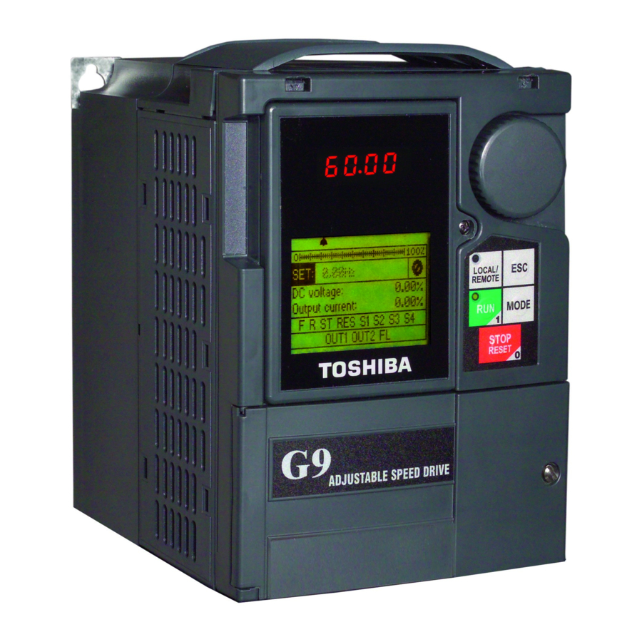
- Page 4 Introduction Congratulations on your purchase of the Toshiba 9-Series ASD. The 9-series ASD has been designed to provide excellent speed and torque control in an open-loop feedback configuration. The 9-series ASD performance can be further enhanced by using either process-based or speed-based PID control.
- Page 5 Contacting Toshiba’s Customer Support Center Toshiba’s Customer Support Center can be contacted to obtain help in resolving any Adjustable Speed Drive system problem that you may experience or to provide application information. The center is open from 8 a.m. to 5 p.m. (CST), Monday through Friday. The Support Center’s toll free number is US (800) 231-1412/Fax (713) 937-9349 —...
- Page 6 About This Manual This manual was written by the Toshiba Technical Publications Group. This group is tasked with providing technical documentation for the 9-Series family of ASDs. Every effort has been made to provide accurate and concise information to you, our customer.
-
Page 7: Table Of Contents
Table of Contents System Control Using PID....................1 Process/Speed PID Control....................2 Select the PID Mode ....................2 Specify the Process Reference Value................2 Specify the Feedback Response ................... 4 Set the Limit Parameters ....................6 Set the PID Gain Parameters ..................6 Simple Position PID Control .................... - Page 8 PID Control Manual Buy: www.ValinOnline.com | Phone 844-385-3099 | Email: [email protected]...
-
Page 9: System Control Using Pid
System Control Using PID PID is an operating mode that maintains a constant system output by comparing the monitored system output (feedback) to a setpoint and compensating for the difference between the two. System adjustments are increased or decreased as a function of the received feedback. This self-correcting action eliminates the requirement for constant operator intervention. -
Page 10: Process/Speed Pid Control
Figure 3. Diagram for F359 = Position PID. Position Completion Range F381 Position PID Control Reference Value F381 Position Completion Range Feedback Signal Process/Speed PID Control Select the PID Mode Select the PID mode at parameter F359 and the PID feedback source at parameter F360. Position PID is addressed specifically in Simple Position PID Control on pg. - Page 11 Figure 4. Process reference set with external signal. 3-Phase Input Pressure sensor Pump Process reference value Desired process value: 15 psi DC: 5 V (0 – 10 V) Sensor Range: Process feedback 10 - 20 psi DC: 4 – 20 mA IICC Note: On the 9-Series ASD, set SW301 to either Current or Voltage as the feedback signal...
-
Page 12: Specify The Feedback Response
Specify the Feedback Response For V/I frequency control establish the response slope of the ASD by entering two parameter pairs. Each parameter pair consists of an input point setting (F202 and F204) and a corresponding frequency (F201 and F203) at that setting. If using either RR or RX for frequency control, set their respective response slope parameters, F210 –... - Page 13 Example: Invert the Response Slope Using an External Switch. Use the S3 terminal as a PID normal/inverse slope characteristic switching signal input terminal. Parameter Selectable Functions Parameter Name Setting Number Range F117 Input Terminal 7 (S3) 0 – 131 54 - PID Positive/Negative Slope Switching This figure illustrates the PID feedback value (maximum frequency: 80 Hz) to the V/I terminal using the S3 terminal to switch between the positive and negative response slope.
-
Page 14: Set The Limit Parameters
Set the Limit Parameters Set the high-low limit parameters. Some parameters are mode specific, as indicated in the following table. Table 1. Limit parameters applicability. Limit Parameters Process PID Speed PID F364, F365 – PID Deviation Upper and Lower Limit F368, F367 –... -
Page 15: Additional Pid Related Commands
Parameters Function Setting F375 Number of PG Input Pulses 12 – 9999 F376 Number of PG Input Poles F381 Simple Positioning Completion Range F111-F118 (any one) Simple Positioning Additional PID Related Commands Switch to Open Loop Operation Switching between PID control and open loop operation can be done with a discrete input. Use the PID Control OFF selection, Input Terminal functions 36 or 37, to switch from PID operation (automatic operation) to open loop operation (manual operation). -
Page 16: Scaling The Analog Input Signal
Scaling the Analog Input Signal Any two set points may be used to establish a response slope for the ASD. It is not necessary that the two set points be at 0% and 100% of the feedback signal range. Weak feedback signals can compensated for by adjusting the set points. For instance, if the feedback signal for the voltage input terminal below were only 3 –... - Page 17 Figure 11. Examples of feedback slopes. F204 F204 80 Hz 80 Hz F202 F202 0 Hz 0 Hz 10 V 20 mA 4 mA F203 F203 F201 F201 100% 100% Example: V/I used as a Voltage Input Terminal Example: V/I used as a Current Input Terminal F219 F213 80 Hz...
-
Page 18: Pid Control Parameter Summary
PID Control Parameter Summary The PID-related ASD parameters are summarized in the table below. Table 3. PID control parameters. Parameter Parameter Name Adjustment Range Default Setting Number 1: V/I 2: RR 3: RX 4: Not Used 5: EOI Keypad 6: RS485 F004 Frequency Mode 1 7: Communications Option Board... - Page 19 Parameter Parameter Name Adjustment Range Default Setting Number F240 Starting Frequency 0.00 – F011 Hz 0.10 F241 Run Frequency 0.00 – F011 Hz 0.00 F242 Run Frequency Hysteresis 0.00 – 30.00 Hz 0.00 F243 End Frequency 0.00 – 30.00 Hz 0.00 F270 Jump Frequency 1...
-
Page 20: Parameter Descriptions
Parameter Parameter Name Adjustment Range Default Setting Number 0: Disabled 1: V/I 2: RR 3: RX 4: Not Used 5: EOI Keypad 6: RS485 F660 Adding Input Selection Override 7: Communications Option Board 0: Disabled 8: RX2 (AI1) 9: Option V/I 10: UP/DOWN Frequency (terminal board) 11: Pulse Input (option) 12: Pulse Input (motor CPU) - Page 21 F015 — V/f Pattern establishes the relationship between the output frequency and the output voltage. When using the Easy Position PID function set this parameter to 8 - PG Vector Feedback Control (Speed/Torque). F201, F203— V/I Input Point 1, 2 Setting set the two points that establish the V/I response slope. These two settings are entered as a percentage of F011.
- Page 22 F360 — PID Feedback Signal disables/enables PID feedback control. Set this parameter to enable PID and select the feedback source. 0: PID Control Disabled 1: V/I 2: RR 3: RX 4: RX2 (AII) 5: Option V/I 6: PG Feedback Option F361 —...
- Page 23 F364 — PID Feedback Deviation Upper Limit sets the maximum amount that the feedback signal may increase the output signal. F365 — PID Feedback Deviation Lower Limit sets the maximum amount that the feedback signal may decrease the output signals. F366 —...
- Page 24 F660 — Adding Input Selection enables or disables output frequency adjustment via an external source. If enabled, the selected input is used as a modifier of the programmed Output Frequency. F661 — Multiplying Input Selection enables or disables output frequency adjustment via an external source.