ABB Magne 3 Product Manual
Electromagnetic process lock
Hide thumbs
Also See for Magne 3:
- User instructions (26 pages) ,
- Excerpts from the original instructions (8 pages)

Related Manuals for ABB Magne 3


Summary of Contents for ABB Magne 3
- Page 1 — SA F E T Y PR OD U CTS Magne 3 and Magne 4 Electromagnetic Process Lock Product Manual 2TLC172315M0201 Rev.M3 ORIGINAL INSTRUCTIONS abb.com/lowvoltage...
- Page 2 ABB Electrification Sweden representative if you have any questions or comments. Suitablity for use ABB shall not be responsible for conformity with any standards, codes, or regulations that apply to the combination of products in the customer’s application or use of the product.
-
Page 3: Table Of Contents
Reading prerequisites .........................5 Special notes ..........................5 2 Safety ............................6 Safety precautions ........................6 3 Product description........................7 Magne 3 ............................7 Magne 4............................7 Accessories and parts ........................ 8 4 Installation...........................9 Installation precautions ......................9 Minimum safety distance......................10 Installation instructions ...................... - Page 4 10 Model overview ......................... 31 10.1 Magne models ..........................31 10.2 Accessories and spare parts ....................31 11 Dimensions ..........................33 12 Technical data ........................... 35 13 EC Declaration of conformity ....................38 2TLC172315M0201 Rev.M3...
-
Page 5: Introduction
This document is intended for authorized personnel. Reading prerequisites It is assumed that the reader of this document has knowledge of the following: • Basic knowledge of ABB safety products • Knowledge of machine safety • Knowledge of safety devices and process locks... -
Page 6: Safety
Safety Safety precautions The safety precautions must be followed during installation, operation, maintenance and troubleshooting. It is the responsibility of the user to ensure the correct overall functionality of its systems and machines. Warning! Carefully read through the entire product manual before using the device. Warning! The devices shall be installed by authorized personnel following the Safety regulations, standards and the Machinery directive. -
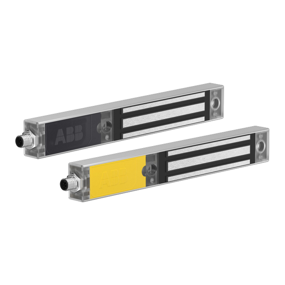
Page 7: Product Description
Magne can be installed on a door, preferably using an ABB mounting kit, available for sliding doors or hinged (conventional) doors. See chapter ‘Mounting kits’. Magne 3 Magne 3 keeps a door locked. If used in safety applications, Magne 3 needs to be complemented with an external interlocking device. Magne 4 Magne 4 keeps a door locked with integrated interlocking. -
Page 8: Accessories And Parts
Accessories and parts A standard Magne installation includes a Magne, an anchor plate and, with Magne 4, an Eva actuator. Anchor plate and Eva actuator are ordered separately. Several accessories are available. See chapter ‘Model overview’ for ordering codes and further details. Anchor plate must be ordered with every Magne. -
Page 9: Installation
Installation Installation shall be done in accordance with a risk assessment for the individual application. Installation shall be carried out by authorized personnel and in accordance with instructions in this document. Please read and understand Magne and Eden product manuals before starting. Installation precautions Warning! All safety functions shall be tested before starting up the system. -
Page 10: Minimum Safety Distance
Adam sensor in Magne 4 needs to learn the Eva code. For Magne 3 the blue LED will illuminate with a solid light when connected. For Magne 4 the green LED will illuminate with a solid light. The blue LED will illuminate with a solid light when the locking signal is activated. -
Page 11: Mounting Kits
To achieve proper fitting, it is recommended to use available mounting kits on installation. The mounting kits include a separate installation guide and screws and nuts necessary to install Magne on ABB Quick-Guard © fencing system. Note! Magne, Eva, anchor plate and cellular rubber are not included in the mounting kits and need to be ordered separately. -
Page 12: Installation On Sliding Door
4.3.3 Installation on hinged door JSM D28 is a handle profile in aluminum for Magne 3 and Magne 4 to be used on hinged doors. Designed for doors with a minimum opening radius of 200 mm. JSM D21C and JSM D24 mounting kits are designed for hinged doors with 5-15 mm door gap. -
Page 13: Installation Anchor Plate
Axle Holding force at door handle Holding force (kN) Offset between Magne unit and door handle (m) 4.3.4 Installation Anchor plate Anchor plate (B) is installed with cellular rubber (C) between the anchor plate and the bracket (G) mounted on the door. The cellular rubber is attached to the anchor plate with adhesive tape and enables the anchor plate to adjust to Magne. -
Page 14: Positioning And Orientation Of Eva With Magne 4
Make sure the surfaces of the electromagnet (A) and the anchor plate (B) are completely parallel, i.e. that full contact is obtained when the door is closed. If ABB mounting accessories are not used, make sure the anchor plate cannot rotate. If the anchor plate tilts, the holding force of the lock can be significantly reduced or eliminated. - Page 15 To decrease distance Z, install distance plate (DA 1B) between the Eva unit and the bracket holding Eva. 2TLC172315M0201 Rev.M3...
-
Page 16: Connections
Safety signal DYNlink signal – one channel Magne DYN models use the ABB DYNlink signal as safety signal and must be used with ABB Vital safety controller and/or ABB Pluto safety PLC. All products using the DYNlink signal can be mixed and connected in series. Up to 30 DYNlink devices with a Vital and up to 10 DYNlink devices per Pluto input can be connected while maintaining PL e (EN ISO 13849-1:2015). -
Page 17: Magne 3X
Magne 3X Male and female M12 5-pole connectors seen from cable side. M12 5-pole connector Brown Locking signal +24 VDC White Not used Blue Black Not used Grey Info output, locked Warning! The info output is non-failsafe and shall never be used to control a safety application. -
Page 18: Magne 4X Dyn
Magne 4X DYN Male and female M12 5-pole connectors seen from cable side. M12 5-pole connector Brown +24 VDC White DYNlink signal in Blue Black DYNlink signal out Grey Locking signal +24 VDC Warning! The DYNlink signal is used to control the safety application. Note! Several Magne 4X DYN units can be connected using a M12-3S Y-connector. -
Page 19: Magne 4 Dyn-Info
Magne 4 DYN-Info Male and female M12 8-pole connectors seen from cable side. M12 8-pole connector White DYNlink signal in Brown +24 VDC Green Locking signal +24 VDC Yellow Grey Info output (Adam and Eva closed & Magne locked) Pink DYNlink signal out Blue Not used... -
Page 20: Magne 4 Dyn-2Info
Magne 4 DYN-2Info Male and female M12 8-pole connectors seen from cable side. M12 8-pole connector White DYNlink signal in Brown +24 VDC Green Locking signal +24 VDC Yellow Grey Info output (Adam and Eva closed) Pink DYNlink signal out Blue Info output (Locked) Warning! The info output is non-failsafe and shall never be used to control a safety... -
Page 21: Magne 4 Ossd-Info
Magne 4 OSSD-Info Male and female M12 8-pole connectors seen from cable side. M12 8-pole connector White OSSD1 out Brown +24 VDC Green OSSD1 in (+24 VDC for the first device after the safety control unit) Yellow OSSD2 in (+24 VDC for the first device after the safety control unit) Grey Info output (Adam and Eva closed &... -
Page 22: Serial Connections
Serial connections To install the safety circuit in a correct way, follow relevant examples of serial connections below. Magne 4 can be connected in series. It is not possible to combine OSSD and DYNlink signals in a safety circuit. If only one OSSD device is used, or if Magne 4 OSSD is the first unit in the series, +24 VDC must be connected to OSSD1 In and OSSD2 In. -
Page 23: Magne 4 Dyn-2Info And Pluto
Magne 4 DYN-2Info and Pluto Magne 4 DYN-2Info and Pluto (Drawing ID: 2TLC010021T0006) Magne 4 OSSD-Info and Pluto Magne 4 OSSD and Pluto (Drawing ID: 2TLC010021T0003) 2TLC172315M0201 Rev.M3... -
Page 24: Magne 4X Dyn, Pluto And M12-3S
Magne 4X DYN, Pluto and M12-3S Magne 4X DYN, Pluto and M12-3S (Drawing ID: 2TLC010021T0004) 2TLC172315M0201 Rev.M3... -
Page 25: Magne 4 Ossd-Info And Sentry
Magne 4 OSSD-info and Sentry Magne OSSD and Sentry (Drawing ID: 2TLC010021T0002) Magne 4 OSSD-Info, Sentry and M12-3G Magne OSSD Sentry and M12-3G (Drawing ID: 2TLC010021T0001) 2TLC172315M0201 Rev.M3... -
Page 26: Functions
LED Indications Status LED indications show the status of Magne and its outputs. Magne 3 and Magne 4 have one blue LED (locked/unlocked indicator). Magne 4 also has one green and one red LED (Eva position indicator). Model... -
Page 27: Maintenance
That may impair the safety of the device, which could lead to serious injury to personnel. Warning! ABB will not accept responsibility for failure of the switch functions if the installation and maintenance requirements shown in this document are not implemented. -
Page 28: Troubleshooting
Troubleshooting LED indications Magne 3 and Magne 4 LED Indications: LED indication Probable cause Action No LED light No voltage Check +24 VDC power supply. Blue flashing Anchor plate is missing Check anchor plate position. or not centered Magne 4 LED indications:... -
Page 29: Low Or No Holding Force
This section only applies to Magne 4. Same tests shall be performed when using an external interlocking safety device together with Magne 3. Check the safety functions by following these steps: 1. Interrupt the safety circuit before this unit when Eva is within sensing distance to Adam (door closed). - Page 30 9. Connect the power supply to Magne. The programming of the new Eva is completed when the LED on Magne illuminates solid green. Erase code in Magne 4 OSSD Move the old Eva out of sensing distance from Adam. Disconnect the power supply from Magne (0 V should always be connected). Connect +24 VDC to OSSD1 Out and OSSD2 Out.
-
Page 31: Model Overview
Adam AND Magne is locked. 10.2 Accessories and spare parts Accessories are not included in Magne and need to be ordered separately. All mounting kits include screws and nuts necessary to install Magne on ABB Quick-Guard® fencing systems. Type Order code... - Page 32 JSM D24 2TLA042023R0300 Mounting kit for Eva used on hinged door. JSM D27 2TLA042023R1000 Door handle for JSM D21C. JSM D28 2TLA042023R0100 Aluminium door handle profile used on hinged door (5–15 mm door gap). Covers Magne unit when the door is closed. Fits all Magne. Eva and anchor plate are installed in the profile.
-
Page 33: Dimensions
Dimensions All dimensions are in mm. Magne 3 and Magne 4 Anchor plate 32D - without permanent magnet 2TLC172315M0201 Rev.M3... - Page 34 Anchor plate 32E - with permanent magnet B: Permanent magnet Cellular rubber 1B 2TLC172315M0201 Rev.M3...
-
Page 35: Technical Data
Max. 20 mA Cable dimension Cable dimensioning should be checked when connecting several units in series. Standard cables from ABB have a cross sectional area of 0.34 mm . Magne does not cause any power surge when locking is activated. - Page 36 Magne 4 DYN: DYN output 15 mA (current limited) Response time at activation <100 ms Response time at <30 ms deactivation Magne 4 OSSD: OSSD output Max. 50 mA per output (current limited) Response time at activation <100 ms Response time at First unit <30 ms deactivation For each additional unit <...
- Page 37 The Limited Voltage / Current source must comply with Power source one of the following: A) An isolating device such that the maximum open circuit voltage potential available to the circuit is not more than 30 VDC and the current is limited to a value not exceeding 8 amperes measured after one minute of operation.
-
Page 38: Ec Declaration Of Conformity
EC Declaration of conformity 2TLC172315M0201 Rev.M3...