Table of Contents
Quick Links
Table of Contents

Related Manuals for GE OptiSonde


Summary of Contents for GE OptiSonde
- Page 1 Sensing OptiSonde™ General Eastern Chilled Mirror Hygrometer User’s Manual...
- Page 2 Sensing OptiSonde™ General Eastern Chilled Mirror Hygrometer User’s Manual 910-282A-GE October 2007 OptiSonde is a General Eastern Instruments product. General Eastern Instruments has joined other GE high-technology sensing businesses under a new name—GE Sensing.
- Page 3 October 2007 Warranty Each instrument manufactured by GE Sensing is warranted to be free from defects in material and workmanship. Liability under this warranty is limited to restoring the instrument to normal operation or replacing the instrument, at the sole discretion of GE Sensing. Fuses and batteries are specifically excluded from any liability.
- Page 4 2. If GE Sensing instructs you to send your instrument to a service center, it must be shipped prepaid to the authorized repair station indicated in the shipping instructions.
-
Page 5: Table Of Contents
October 2007 Table of Contents Chapter 1: Features and Capabilities Introduction................1-1 Electronics Enclosure . - Page 6 Logging OptiSonde Data........
- Page 7 October 2007 Table of Contents (cont.) Chapter 5: Maintenance Minor Maintenance of Sensor Optics ........... . 5-1 Cleaning and Balancing the Sensor Mirror .
- Page 8 Comparing OptiSonde Sensors........
- Page 9 Chapter 1...
- Page 10 Features and Capabilities Introduction........... . 1-1 Electronics Enclosure .
-
Page 11: Chapter 1: Features And Capabilities
The GE Sensing OptiSonde™ is a multi-purpose chilled-mirror hygrometer, suitable for use in a wide variety of applications. The OptiSonde can function with the GE Sensing one and two-stage chilled-mirror sensors to provide the following measurement ranges (depending on the sensor selected): •... -
Page 12: Electronics Enclosure
IP65 enclosure See Chapter 2, Installation, for details on how to mount the OptiSonde. Front Panel The OptiSonde’s front panel is shown in Figure 1-2 below. The panel ENTER includes: a 128 X 64 graphical display, keys, and four arrow keys to the right of the display screen. -
Page 13: Input/Output Capability
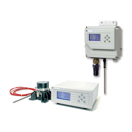
The OptiSonde uses the GE Sensing patented Programmable Automatic Contaminant Error Reduction (PACER) system for automated self-cleaning and optics rebalancing. Detailed specifications for the OptiSonde are given in Appendix A. The System System Components A complete OptiSonde system consists of the following items: •... -
Page 14: Sensors
October 2007 Sensors The OptiSonde is configured with a chilled-mirror dew point sensor. The specific sensor is chosen according to the expected dew point range and the environment in which the dew point is to be determined. In addition, the OptiSonde is supplied with a temperature sensor. - Page 15 Chapter 2...
- Page 16 Installation Introduction........... . 2-1 Benchtop Installation .
-
Page 17: Introduction
October 2007 Introduction This chapter explains the installation of the benchtop and wall-mount versions of the OptiSonde, the various sensors used with the system, and the I/O and power wiring. Benchtop Installation Mounting the Benchtop The OptiSonde benchtop dimensions are shown in Figure 2-1 below. - Page 18 Sensors Connect the dew point sensor cable to the 25-pin connector on the OptiSonde’s rear panel (see Figure 2-2 below). Connect the optional temperature sensor cable to the 9-pin temperature connector on the rear panel. Other I/O wiring connects to the appropriate terminal block.
-
Page 19: Wall-Mount Installation
October 2007 Wall-Mount Installation The OptiSonde Wall-Mount unit is designed to mount on a flat, vertical surface, such as a wall or panel. To mount the wall-mount version, see Figure 2-4 and Figure 2-5 below. Installing the Wall-Mount 4.49 [114] 8.17... -
Page 20: Wiring The Wall-Mount
7.80 [198] Note: units are inches [mm] Figure 2-5: OptiSonde Wall-Mount - Mounting Hole Locations For mounting, secure the unit to a wall or panel using all four mounting holes. Use stainless hardware, a minimum of 2 inches long, #8 screws with washers. Screws should go directly into wood studs. - Page 21 October 2007 Wiring the Wall-Mount All connections to the wall-mount unit are made through the panel at (cont.) the bottom of the case as shown in Figure 2-6 below. Any I/O cabling is brought into the unit through glands at the lower right of the case and connects to the terminal blocks inside the case.
-
Page 22: Input Power
October 2007 Input Power Power wiring enters the case through a gland fitting at the lower right of the unit and connects to a screw terminal block mounted on the right side of the case. The voltage, frequency and power ratings are listed on the bottom of the unit. -
Page 23: Output Wiring
Figure 2-8 below shows the wall-mount connections. The Wall-Mount OptiSonde input/output terminal blocks are located inside the front door as shown in Figure 2-6 on page 2-5. Cabling is brought in through the glands on the bottom of the unit and wired to the terminal blocks shown in Figure 2-8 below. -
Page 24: Analog Outputs
October 2007 Analog Outputs Note: When the OptiSonde is being programmed, the analog outputs provide 4–20 mA signals representing the designated parameters. For 4–20mA output, connect to terminals labelled 4–20 (+) and • RTN (–). Note: The maximum load allowed for current output is 500 Ohms. - Page 25 October 2007 Set Point Alarm For the Set Point alarm type, the alarm band provides hysteresis to prevent frequent operation of the alarm relay when the parameter is near the specified value. The relay is activated when the parameter exceeds the upper limit, and deactivated when the parameter goes below the lower limit.
-
Page 26: Serial Output
October 2007 Outer Band Alarm For the Outer Band alarm, the alarm relay activates whenever the parameter value is greater than the upper limit or less than the lower limit. Figure 2-11: Outer Band Alarm Serial Output The Serial Output connector is located on the rear panel of the benchtop unit (see Figure 2-2 on page 2-2), and inside the wall-mount unit (Figure 2-6 on page 2-5). -
Page 27: Sensor Information
Sensor Information GE Sensing produces a variety of sensors compatible with the OptiSonde, ranging from one to two stages of thermoelectric cooling. A comparison chart listing specifications of each sensor appears in Appendix D. The following sections provide information on installing the following GE Sensing dew point sensors: •... -
Page 28: Sampling Lines
October 2007 Sampling Lines Keep the length of sample tubing between the source and the sensor short, for quick response and highest accuracy. All sampling line compression fittings provided with the sensor are for ¼-inch diameter tubing, unless otherwise specified at the time of order.The material used for the inlet lines can have an important effect on the validity of the readings. -
Page 29: Filter Requirements
On the other hand, filtering tends to slow the system’s response, particularly at low frost points. The model BF12-SS filter may be used inline; GE Sensing’s application engineers would be pleased to review your application and recommend an appropriate sampling system. -
Page 30: Flow Rate
/h (∼ 1 liter/ min) is ideal for most applications. Sensor Installation This section provides installation details for the GE Sensing line of chilled-mirror humidity sensors. Model 1111H Sensor The Model 1111H is an open-type sensor (see Figure 2-12 below) with 45°C depression capability at 25°C @ 1 ATM. -
Page 31: Model D-2 Sensor
October 2007 Model D-2 Sensor The Model D-2 is a general purpose, two-stage sensor with 65°C (117°F) of depression capability at 25°C @ 1 ATM. It features wetted parts of stainless steel and glass, for durability in demanding industrial applications. The Model D-2 can be used as a benchtop sensor, mounted to a heat sink, or mounted to a cooling fan for maximum operating range. -
Page 32: Connecting The Sensors
October 2007 Connecting the Sensors Dew point and temperature sensors provided by GE Sensing for the OptiSonde monitor are pre-wired with connectors installed. Plug these connectors into their corresponding sockets as shown in Figure 2-2 on page 2-2 for the benchtop unit, or Figure 2-6 on page 2- 5 for the wall-mount unit. - Page 33 Chapter 3...
- Page 34 Operating the OptiSonde ........
-
Page 35: Chapter 3: Operation
Details are given in Chapter 5, Maintenance. Normal Operation Normal operation of the OptiSonde is very simple. First, apply power to the wall-mount unit. For the benchtop unit, switch the main power switch on the rear to ON (I). -
Page 36: Operating The Optisonde
The parameters chosen during programming are displayed numerically in the middle of the screen. For programming, see Chapter 4. A typical OptiSonde display screen is shown in Figure 3-1 below. The system status and heating/cooling indicator (small arrow) are shown in the upper right, and the balance indicator is shown in the lower left. -
Page 37: Status Line Indications
October 2007 Status Line Indications The status line at the top of the display shows whether the unit is ready for normal operation, or is still in its start-up phase, or needs service. The following is a complete list of status indications: Table 3-1: Status Indications Indication Meaning... -
Page 38: Factory Default Settings
Pressure 101.325 kPa (typical atmospheric pressure @ sea level). *A status flag gives an indication, via the RS-232 interface, of the OptiSonde status, such as “Control” and “PACER,” as well as the state of the alarm (“ALARM” or “_______”). Operation... -
Page 39: Sensor Balancing
The interval and type of balance are configurable as described in the OptiSonde programming chapters. If the Service indicator is displayed after a balance operation, the sensor may need to be adjusted (see Minor Maintenance of Sensor Optics on page 5-1). -
Page 40: Supercooled Dew Points
October 2007 Supercooled Dew Points Slightly below the freezing point, water can exist in a supercooled liquid state for extended periods of time. Extra care may be needed when making measurements in the frost point region of 0 to –20°C, because the mirror temperature may temporarily stabilize at the supercooled dew point, 0.5 to 1°C below the actual frost point. - Page 41 October 2007 Water-Soluble Contaminants which readily dissolve in water, such as naturally Contaminants occurring salts, are detrimental to accurate vapor concentration measurement by any condensation method. These materials readily go into solution with the water condensate on the mirror surface, and then reduce the vapor pressure in accordance with Raoult’s Law.
-
Page 42: Mirror Flooding
If the pressure of the gas is increased or reduced from atmospheric pressure, but the mixing ratio (moisture content) stays constant, the dew point is correspondingly increased or decreased. The OptiSonde displays the dew/frost point at the pressure to which it has been programmed. - Page 43 Chapter 4...
-
Page 44: Chapter 4: Programming The Optisonde
Programming the OptiSonde Introduction........... . 4-1 Programming Technique . -
Page 45: Introduction
October 2007 Introduction The OptiSonde can be easily programmed to choose the data to be displayed, the data to be output on the analog or serial outputs, and the alarm settings. A typical data display appears in Figure 4-1 below:... -
Page 46: Programming Technique
Below is the general method for programming the unit: 1. To access the programming menus, press the key. If the OptiSonde keys are locked, press the key, followed by the key, and then press the key again. Then press again to enter the Main Menu. -
Page 47: Programmable Functions
(up to three) for the parameter shown in each line. You can also select Reverse to change the screen display from the default of blue letters on a white background to white letters on a blue background. Programming the OptiSonde... -
Page 48: Analog Outputs
4. Enter the actual value as read from the DVM/calibrator. 5. Select TRIM SPAN . The output changes to 20.00 mA. 6. Enter the actual value as read from the DVM/calibrator. 7. Exit the TRIM setting. You have completed output calibration. Programming the OptiSonde... -
Page 49: Alarms
Inner Band: Alarm activates when parameter is between upper and lower limits. • Outer band: Alarm activates when parameter is outside upper and lower limits. • Control: Alarm activates when the OptiSonde is actively controlling mirror temperature. • Service: Alarm activates when the Service indicator is activated. • PACER... -
Page 50: Logging Optisonde Data
(for a log stored on the PC). Press . The current selection is part of the Logging menu header. OptiSonde can run two logs at any one time, one for the SD card and one for the PC. (The two logs can measure different Select parameters.) To switch between the logs, return to... - Page 51 • The OptiSonde will display up to 8 log files for management. However, up to 512 log files can be stored on the SD card. You should erase logs from the SD card when they have been safely transferred to a PC for storage.
- Page 52 (Internal or File size), Transfer (transfer closed log to PC), logs only) New Log (set up new log), Erase (delete log from OptiSonde) Units Set up to eight units to log. See Table 4-2 on page 4-3. Enter the output interval in seconds (for Serial Interval Enter a number (up to 86400).
-
Page 53: Optisonde Settings
(month, date and year). Pressure Pressure value to be used. Enter line pressure in kPA. Notify Enter a time at which the OptiSonde Off, 6 Months, 12 Months, 18 Months, 24 should be recalibrated. Months Programming the OptiSonde... -
Page 54: Automatic Cleaning And Balance Function
October 2007 Automatic Cleaning and Auto PACER OptiSonde analyzers can run the self-cleaning and Balance Function rebalancing cycles at a preset time after the last cycle was run. The automatic balance cycle will always run upon power up of the analyzers.To program the Automatic Cleaning &... - Page 55 October 2007 Automatic Cleaning and 4. Determine the Interval at which the OptiSonde will perform Balance Function (cont.) cleaning and balancing. a. From the Balance Interval menu, enter b. Use the arrow keys to enter the interval time in days (or decimal fractions of days), up to 90 days.
-
Page 56: Service Options
Please contact an applications or service engineer at GE Sensing if access to these menus is required. Normal operation of the OptiSonde does not require access to the information contained in the Service menu. System Information... - Page 57 Chapter 5...
- Page 58 Maintenance Minor Maintenance of Sensor Optics......5-1 Field Replacement of Sensor Mirrors ......5-5 Test and Calibration .
-
Page 59: Chapter 5: Maintenance
However, there are occasions when particulate matter and water-soluble contaminants reduce sensor mirror reflectance and system accuracy (see Contamination on page 3-6). Three features of the OptiSonde system allow users to monitor and adjust the mirror: • The balance indicator (shown in Figure 5-1 below) provides a graphic display of how much light is received by the mirror’s... -
Page 60: Procedure For Cleaning And Balancing The Sensor Mirror
Screwdriver or hex driver for some sensors • Cleaning solution 1. From the OptiSonde analyzer, press the key. The Select Function window appears. Press the up arrow key to reach HEAT. 2. Allow the dew point temperature (mirror temperature) to attain the maximum value. - Page 61 October 2007 Procedure for Cleaning 5. If the square is not in the center of the balance bar, use the screw and Balancing the Sensor or hex driver to adjust the optical bias screw (shown in Figure 5-3 Mirror (cont.) below) on the sensor until the marker is in the center of the bar.
- Page 62 When a stable dew or frost layer is attained, you will see the word Control in the lower left. The OptiSonde is now reading the correct dew/frost point and a stable dew or frost layer has been established.
-
Page 63: Field Replacement Of Sensor Mirrors
October 2007 Field Replacement of One advantage of using a GE Sensing chilled mirror dew point sensor Sensor Mirrors is that the mirror is user-replaceable. The sensor does not have to be returned to the factory for replacement of the reflective surface, unless that is desired. -
Page 64: Replacing The Sensor Mirror
7. Carefully clean the mirror surface, using a cotton swab and the GE Sensing cleaning solution supplied with the maintenance kit. Distilled alcohol or diluted alcohol is also acceptable. 8. Replace the cover and return the sensor to normal operation. -
Page 65: Test And Calibration
October 2007 Test and Calibration The procedures in this section effectively test and/or calibrate the following aspects of the OptiSonde: • Startup and power supply voltage • Normal sensor operation • Front panel display • Digital and analog outputs. The unit has been completely tested and calibrated at the factory, and is ready to plug in and operate. -
Page 66: Incorrect Dew Point Display
October 2007 Incorrect Dew Point If the dew/frost point reads incorrectly, first check the standard Display preventive maintenance items: Clean and balance the sensor mirror (refer to page 5-1). An alternative method for checking the accuracy of the unit’s electronics is to use a precision resistance decade box in place of the platinum thermometer. -
Page 67: Balance" Remains On The Status Line
October 2007 “Balance” Remains on the Check that the sensor and sensor cable are connected. If necessary, Status Line connect them, and the unit will complete the PACER cycle after a short time (5 to 15 minutes). The sensor bridge may be out of balance (refer to page 5-1). No Analog Output If there is no analog output, but the digital display indicates correctly, check the analog output scaling. - Page 68 Appendix A...
- Page 69 Specifications Performance ........... A-1 Functionality .
-
Page 70: Performance
0.05°C (0.09°F) Repeatability ±0.1°C (±0.18°F) Measurement Ranges Chilled Mirror Sensors: 1111H, 1111H-GE, 1211H, D-2 (available) Range: one-stage 45° depression @25°C and 1 ATM two-stage 65° depression @25°C and 1 ATM dew/frost point, depending on sensor used Temperature Sensor: T-100E: –100°C to +100°C (–148°F to +212°F) Recommended 0.5 to 2.5 scfh (0.25 to 1.25 L/min) -
Page 71: Functionality
October 2007 Functionality Outputs Two linear simultaneous parameters, 0/4-20 mA (isolated) with 250Ω or 500Ω maximum load resistance Digital Interface RS-232 Alarms Relay (optional): Form C (SPDT) 7 A, 30 VDC (resistive load) Display 128 X 64 pixel monochrome LCD Power 100-240 VAC (+/-10%), 50-60 Hz 18 (minimum) -32 (maximum) VDC (benchtop only on special order) -
Page 72: Physical (Bench Mount
10.48" H × 8.2” W × 4.5" D (26.6 cm × 20.8 cm × 11.4 cm) Weight 5.3 lb (2.4 kg) Environmental IP-65 Optional Accessories PTFE-GE Filter for 1111H-GE PTFE FM-1 Rotameter BF12SS Inline filter Specifications subject to change without notice. Specifications... - Page 73 Appendix B...
-
Page 74: Appendix B: Humidity Equations And Conversion Chart
Humidity Equations and Conversion Chart Introduction........... . B-1 Vapor Pressure . -
Page 75: Introduction
October 2007 Introduction The following symbols appear in the equations below: e = Vapor Pressure, millibars = Vapor Pressure with respect to ice, millibars = Vapor Pressure with respect to water, millibars = Saturation vapor pressure, ice, millibars = Saturation vapor pressure, water, millibars P = Total Pressure, millibars T = Temperature, °C = Ambient temperature, °C... -
Page 76: Humidity
October 2007 Humidity Relative Humidity is defined as the ratio of the water vapor pressure (e) to the saturation vapor pressure (e ) at the prevailing ambient or dry bulb temperature (Ta): ⎛ ⎞ (B-3) ---- - ------------------- - ⎝ ⎠... - Page 77 October 2007 Figure B-1: Graphical Humidity Conversion Chart Humidity Equations and Conversion Chart...
- Page 78 Appendix C...
-
Page 79: Appendix C: Configuring The Serial Interface
Configuring the Serial Interface Wiring to a Personal Computer ........C-1... - Page 80 • 5 - Signal ground (GND) To send the output of a benchtop OptiSonde to a personal computer, use the cable arrangement shown in Figure C-1 below. For a wall- mount OptiSonde, use the wiring shown in Figure C-2 on the next page.
-
Page 81: Wiring To A Personal Computer
October 2007 Wiring to a Personal Computer (cont.) RS232 1. TX 2. RX 3. RTN Figure C-2: Wiring Diagram - Wall-Mount OptiSonde to PC Configuring the Serial Interface... - Page 82 Appendix D...
- Page 83 Measurement Range ..........D-2 Comparing OptiSonde Sensors ........D-3...
-
Page 84: Appendix D: Chilled Mirror Sensors
October 2007 Introduction For use with the OptiSonde hygrometer, GE Sensing offers a choice of three chilled mirror sensors which differ primarily in their depression (cooling) capability. Depression capacity determines the minimum dew point that can be measured. All of the sensors feature low-noise, infrared optics, a field-replaceable mirror, and can be located up to 300 ft (91 m) from the electronics. -
Page 85: Measurement Range
October 2007 Measurement Range The measurement range of a chilled mirror sensor is defined as the temperature range over which a stable dew or frost layer can be maintained on the mirror. Note that in order to acquire a dew or frost layer on the mirror, the depression capability of a sensor must extend below its measurement range. -
Page 86: Comparing Optisonde Sensors
October 2007 Comparing OptiSonde Sensors Table D-1: Chilled Mirror Sensor Comparison Chart Model Model Model 1111H/1111H-GE 1211H System Performance Standard Accuracy* 0.2°C 0.2°C 0.2°C Cooling Stages Depression (at 25°C (77°F), 1 atm, in air) 45°C 65°C 65°C Typical Measurement Range (at given at 25°C... - Page 87 Appendix E...
-
Page 88: Appendix E: Theory Of Operation And Glossary
Theory of Operation and Glossary Theory of Operation ........E-1 The PACER Cycle . -
Page 89: Theory Of Operation
October 2007 Theory of Operation The OptiSonde utilizes condensation hygrometry, which is a precise technique for determining the water vapor content in gases by directly measuring dew point or frost temperatures. Using this technique, a metal mirror is cooled until it reaches a temperature at which a thin layer of condensation begins to form on it. -
Page 90: Hygrometer Calibration
October 2007 Hygrometer Calibration The OptiSonde unit can be sent to the National Institute of Standards and Technology (NIST) in Gaithersburg, Maryland for certification or to any National Standards lab for calibration against their primary humidity standards. A calibrated instrument can then be used as a transfer standard in local laboratories to calibrate lower echelon instruments. -
Page 91: Other Hygrometer Applications
At high dew points (up to 100°C), the sensor is limited by the thermal properties of the solid state OptiSonde components as well as the thermoelectric heat pump capacity. In a typical application measuring sub-ambient dew points, a two- stage thermoelectrically-cooled mirror can reach a temperature approximately 65°C lower than an ambient (heat sink) temperature of... -
Page 92: The Pacer Cycle
Reduction) that is very effective in reducing the Raoult Effect error associated with soluble contaminants, particularly for near-ambient dew points. The OptiSonde is equipped with the PACER cycle as well as AUTO balance as found on earlier models. The user can choose which self-cleaning and balancing routine to run depending on the severity of contamination. -
Page 93: Glossary
The temperature difference by which the chilled mirror can be lowered from the ambient temperature. PACER GE Sensing patented Programmable Automatic Contaminant Error Reduction system, which consolidates soluble contaminants to reduce their effect on system accuracy (see The PACER Cycle on page E-4). - Page 94 Display OptiSonde......4-5 "Balance" Displayed ....5-9 Analog Outputs Incorrect Dew Point .
- Page 95 Benchtop ......2-1 OptiSonde ......3-2 Sampling Lines .
- Page 96 October 2007 Index (cont.) Sample Line Maintenance ....3-8 Testing.......5-7 Sampling Lines.
- Page 97 1100 Technology Park Drive Billerica, MA 01821-4111 Web: www.gesensing.com Ireland Sensing House Shannon Free Zone East Shannon, County Clare...