
Related Manuals for GE T17


Summary of Contents for GE T17
- Page 1 Oil & Gas Flow Model T17 Ultrasonic Flow Transducer Installation Guide 916-128 Rev. D September 2020...
- Page 3 Oil & Gas Model T17 Ultrasonic Flow Transducer Installation Guide 916-128 Rev. D September 2020 www.gemeasurement.com © Copyright 2020. Baker Hughes Company. This material contains one or more registered trademark of Baker Hughes Company and its subsidiaries in one or more countries. All third-party product and company names are trademarks of their respective holders.
- Page 4 [no content intended for this page]...
-
Page 5: Table Of Contents
3.2 Valve Installation for 3-inch Flanges ..............55 Model T17 Installation Guide... - Page 6 6.1 T17 Transducer Physical Specifications........
- Page 7 If you do, serious injury can result. Make sure that power to the auxiliary equipment is turned OFF and locked out before WARNING! you perform maintenance procedures on the equipment. Model T17 Installation Guide...
- Page 8 Environmental Compliance Waste Electrical and Electronic Equipment (WEEE) Directive GE Measurement & Control is an active participant in Europe’s Waste Electrical and Electronic Equipment (WEEE) take-back initiative, directive 2012/19/EU. The equipment that you bought has required the extraction and use of natural resources for its production. It may contain hazardous substances that could impact health and the environment.
-
Page 9: Chapter 1. Introduction
• A BNC style connector for use in connecting the transducer to the flowmeter The T17 transducer is available in standard lengths of 33 in. (840 mm) to 60 in. (1500 mm) and with either a 180 angled head. BNC Connector... -
Page 10: Certification And Safety Statements
“D”, complying with EN 60079-1:2007 and IEC 60079-1:2007 Ex d IIC. Measures must be taken to ensure a good electrical contact and to prevent the threads from self-loosening. The compression fitting is suitable for temperatures –60°C to 250°C. Model T17 Installation Guide... -
Page 11: Chapter 2. Installing The Pipe Nozzles
Introduction Before the T17 transducers can be installed into the pipe, you will need to install pipe nozzles. Nozzles may be installed as part of a fabricated spoolpiece, or by using a hot or cold tapping process with a GE Nozzle Installation Kit. -
Page 12: Nozzle Installation - Diametrical Path
6. “Installing the Second Welding Boss and Nozzle - Diametrical” on page 16 7. Proceed to one of the following: • “Hot Tapping the Pipe - Diametrical” on page 17 • “Cold Tapping the Pipe - Diametrical” on page 17 Model T17 Installation Guide... -
Page 13: Identifying The Nozzle Installation Kit Components - Diametrical
IMPORTANT: You will need to supply eight 5/8” studs with two nuts each (for 3”x 150# flanges), or eight 3/4” studs with two nuts each (for 3”x 300# flanges). Use Figure 4 below to help identify each component. Welding Boss Nozzle Threaded Rod with Washer and Nut Figure 4: Components in Nozzle Installation Kit Model T17 Installation Guide... -
Page 14: Selecting And Marking The First Nozzle Location - Diametrical
When the nozzle installation is complete, the raised faces of the two flanges must be parallel to each other. All hole cutting in live process piping must be performed using equipment WARNING! hot tapping (see “Hot Tapping the Pipe - Diametrical” on page 17). Model T17 Installation Guide... - Page 15 (i.e., 3 o’clock and 9 o’clock positions) for a horizontal pipe. Note: If you cannot find a proper location, please consult with GE Flow Application engineering. 3. At the 3 o’clock position, center punch the pipe to mark the position for the center of the first nozzle, as shown in Figure 7 below.
-
Page 16: Determining And Marking The Second Nozzle Location - Diametrical
2. Due to the possible variation in OD of the pipe, measure the outside diameter of the pipe at four locations between the nozzle centers (see Figure 9 below). Then, calculate the average OD from these measurements. D2 D3 Side View Figure 9: Multiple OD Measurements Model T17 Installation Guide... - Page 17 Make sure the strip overlaps squarely around the pipe and mark the overlap position of the strip, as shown in Figure 11 below. This equals the circumference of the pipe. Overlap Mark Side View Figure 11: Polyester Film Overlap Mark Model T17 Installation Guide...
- Page 18 7. Place the strip of film back on the pipe. This time, line up the overlap mark with the horizontal and vertical scribe lines (see Figure 14 below). Again, make sure you wrap the strip of film squarely around the pipe. Overlap Mark Side View First Edge Figure 14: Placing the Film on the Pipe Model T17 Installation Guide...
- Page 19 Figure 15: Center Punch the Second Nozzle Location 9. Remove the film from the pipe. 10. Scribe 6” long vertical and horizontal lines that intersect at the center-punch mark (see Figure 16 below). Scribe Lines Side View Figure 16: Making Scribe Lines Model T17 Installation Guide...
-
Page 20: Installing The First Welding Boss - Diametrical
The oblique center line should be marked on the side of the true center line that is closer to the second nozzle location, as shown in Figure 17 below. Oblique Center Line True Center Line Side View Figure 17: Scribing the Oblique Center Line Model T17 Installation Guide... - Page 21 6. Remove the clamp and check the welding boss alignment again. If the welding boss is misaligned by 0.02 in. (0.5 mm) or more, remove the welding boss, grind off the welds and reinstall it. Model T17 Installation Guide...
-
Page 22: Installing The First Nozzle - Diametrical
2. Slide the nozzle over the threaded rod, and align the contoured end of the nozzle so it matches the pipe arc. Then slide the jig over the threaded rod, fitting the jig into the welding boss (see Figure 20 below). Figure 20: Inserting the Nozzle and Jig Model T17 Installation Guide... - Page 23 0.6 in. (15 mm) in length. Allow the welds to cool for 30 seconds between tacks. 7. Proceed to complete the root pass and subsequent filler passes as required. 8. Allow the welds to cool, then remove the four studs. Then, remove the nut, washer, jig and threaded rod. Model T17 Installation Guide...
-
Page 24: Installing The Second Welding Boss And Nozzle - Diametrical
First Welding Boss - Diametrical” on page 12 and “Installing the First Nozzle - Diametrical” on page 14. Figure 22: Installing the Second Welding Boss and Nozzle The completed installation should appear as shown in Figure 23 below. NOZZLE 2 PLACES WELDING BOSS 2 PLACES FLOW 45° Figure 23: Completed Diametrical Installation Model T17 Installation Guide... -
Page 25: Hot Tapping The Pipe - Diametrical
The procedure for cold tapping a pipe is the same as the hot tapping procedure. However, an isolation valve is not necessary during the process. The hot tapping medium can be applied directly to the nozzle. Isolation valves will be added after the tapping is complete. Model T17 Installation Guide... -
Page 26: Nozzle Installation - Mr1 Mid-Radius Path
6. “Installing the Second Welding Boss and Nozzle MR1 Mid-Radius” on page 34 7. Proceed to one of the following: • “Hot Tapping the Pipe - MR1 Mid-Radius” on page 35 • “Cold Tapping the Pipe - MR1 Mid-Radius” on page 35 Model T17 Installation Guide... -
Page 27: Identifying The Nozzle Installation Kit Components - Mr1 Mid-Radius
Low Carbon Steel 591-324 SS 316 591-325 1-Piece Forged, 150 lbs Carbon Steel 591-564 Low Carbon Steel 591-565 Reinforced Integral Nozzle SS 316 591-566 300 lbs Carbon Steel 591-567 Low Carbon Steel 591-568 SS 316 591-569 Model T17 Installation Guide... -
Page 28: Selecting And Marking The First Nozzle Location - Mr1 Mid-Radius
±1/16” (±1.6 mm) flanges must be parallel to each other. All hole cutting in live process piping must be performed using equipment WARNING! hot tapping (see “Hot Tapping the Pipe - MR1 Mid-Radius” on page 35). Model T17 Installation Guide... - Page 29 Note: We recommend that you install the nozzles on a chord as near as possible to the horizontal plane for horizontal pipe. If you cannot find a proper nozzle location, please contact GE for assistance. 2. Locate the top of the pipe and put a center punch mark there as a reference mark.
- Page 30 2nd Nozzle --- - D 2W – ------------------ - CHORD D 2W – ------------------ - × Downstream End View Figure 29: Locating the MR1 Nozzles on the Pipe Model T17 Installation Guide...
- Page 31 (see Figure 30 below). Top of Pipe Reference Point Center Point of 1st Nozzle Figure 30: Marking the First Nozzle Location Model T17 Installation Guide...
-
Page 32: Determining And Marking The Second Nozzle Location - Mr1 Mid-Radius
The nozzles cannot be physically mounted on the header pipe if they are mistakenly located at the mirror image of the locations shown above. Model T17 Installation Guide... - Page 33 Thus, one would cut a piece of film 41.783 in. Wide x 168.000 in. Long. Note: In the above example, the tabulated pipe OD of 48.000 in. was used in the calculations for clarity. Ideally, the measured average pipe OD from step 2 above would be used instead. Model T17 Installation Guide...
- Page 34 Note: In the above example, the tabulated pipe OD of 48.000 in. was used in the calculations for clarity. Ideally, the measured average pipe OD from step 2 on the previous page would be used instead. Model T17 Installation Guide...
- Page 35 (see Figure 35 below). Make sure the strip overlaps squarely around the pipe and that the marked line on the film from step 4 is on the outside of the film and is visible when wrapped. Top Reference Point Figure 35: Wrapping the Film on the Pipe Model T17 Installation Guide...
- Page 36 Nozzle Installation Kit (NIK). Model T17 Installation Guide...
-
Page 37: Installing The First Welding Boss - Mr1 Mid-Radius
STD Schedule, 48” pipe. a. From standard pipe tables: pipe OD (D) = 48.000 in. and pipe wall thickness (W) = 0.375 in. b. From GE documentation: welding boss OD (d) = 1.660 in. c. From the 1st equation: Y = (48.000 - (2 x 0.375))/2) x 0.5 = 11.813 in. - Page 38 One end of the oblique centerline should stop at the horizontal scribe line, as shown in Figure 38 below. Oblique Centerline True Centerline Oblique Centerline Ends at Horizontal Line Figure 38: Scribing the Oblique Centerline Model T17 Installation Guide...
- Page 39 6. Remove the pipe strap and check the alignment again. If the welding boss is misaligned by 0.02 in. (0.5 mm) or more, you must remove the welding boss, grind off the welds and reinstall the welding boss. Model T17 Installation Guide...
-
Page 40: Installing The First Nozzle - Mr1 Mid-Radius
2. Slide the nozzle over the threaded rod, and align the contoured end of the nozzle so it matches the pipe arc. Then slide the jig over the threaded rod, fitting the jig into the welding boss (see Figure 41 below). Figure 41: Inserting the Nozzle and Jig Model T17 Installation Guide... - Page 41 0.6 in. (15 mm) in length. Allow the welds to cool for 30 seconds between tacks. 7. Proceed to complete the root pass and subsequent filler passes as required. 8. Allow the welds to cool, then remove the four studs. Then, remove the nut, washer, jig and threaded rod. Model T17 Installation Guide...
-
Page 42: Installing The Second Welding Boss And Nozzle Mr1 Mid-Radius
Figure 43: Installing the Second Welding Boss and Nozzle The completed installation should appear as shown in Figure 44 below. Nozzle (2 places) Welding Boss (2 places) 45º Flow Top View End View Figure 44: Completed MR1 Mid-Radius Installation Model T17 Installation Guide... -
Page 43: Hot Tapping The Pipe - Mr1 Mid-Radius
The procedure for cold tapping a pipe is the same as the hot tapping procedure. However, an isolation valve is not necessary during the process. The hot tapping medium can be applied directly to the nozzle. Isolation valves will be added after the tapping is complete. Model T17 Installation Guide... -
Page 44: Nozzle Installation - Mr2 Mid-Radius Path
6. “Installing the Second Welding Boss and Nozzle MR2 Mid-Radius” on page 52 7. Proceed to one of the following: • “Hot Tapping the Pipe - MR2 Mid-Radius” on page 53 • “Cold Tapping the Pipe - MR2 Mid-Radius” on page 53 Model T17 Installation Guide... -
Page 45: Identifying The Nozzle Installation Kit Components - Mr2 Mid-Radius
Low Carbon Steel 591-561 SS 316 591-562 1-Piece Forged, 150 lbs Carbon Steel 591-570 Low Carbon Steel 591-571 Reinforced Integral Nozzle SS 316 591-572 300 lbs Carbon Steel 591-573 Low Carbon Steel 591-574 SS 316 591-575 Model T17 Installation Guide... -
Page 46: Selecting And Marking The First Nozzle Location - Mr2 Mid-Radius
±1/16” (±1.6 mm) flanges must be parallel to each other. All hole cutting in live process piping must be performed using equipment WARNING! hot tapping (see “Hot Tapping the Pipe - MR2 Mid-Radius” on page 53). Model T17 Installation Guide... - Page 47 Note: We recommend that you install the nozzles on a chord as near as possible to the horizontal plane for horizontal pipe. If you cannot find a proper nozzle location, please contact GE for assistance. 2. Locate the top of the pipe and put a center punch mark there as a reference mark.
- Page 48 2nd Nozzle --- - D 2W – ------------------ - CHORD D 2W – ------------------ - × Downstream End View Figure 50: Locating the MR2 Nozzles on the Pipe Model T17 Installation Guide...
- Page 49 (see Figure 51 below). Top of Pipe Reference Point Center Point of 1st Nozzle Figure 51: Marking the First Nozzle Location Model T17 Installation Guide...
-
Page 50: Determining And Marking The Second Nozzle Location - Mr2 Mid-Radius
The nozzles cannot be physically mounted on the header pipe if they are mistakenly located at the mirror image of the locations shown above. Model T17 Installation Guide... - Page 51 Thus, one would cut a piece of film 41.783 in. Wide x 168.000 in. Long. Note: In the above example, the tabulated pipe OD of 48.000 in. was used in the calculations for clarity. Ideally, the measured average pipe OD from step 2 above would be used instead. Model T17 Installation Guide...
- Page 52 Note: In the above example, the tabulated pipe OD of 48.000 in. was used in the calculations for clarity. Ideally, the measured average pipe OD from step 2 on the previous page would be used instead. Model T17 Installation Guide...
- Page 53 (see Figure 56 below). Make sure the strip overlaps squarely around the pipe and that the marked line on the film from step 4 is on the outside of the film and is visible when wrapped. Top Reference Point Figure 56: Wrapping the Film on the Pipe Model T17 Installation Guide...
- Page 54 Nozzle Installation Kit (NIK). Model T17 Installation Guide...
-
Page 55: Installing The First Welding Boss - Mr2 Mid-Radius
STD Schedule, 48” pipe. a. From standard pipe tables: pipe OD (D) = 48.000 in. and pipe wall thickness (W) = 0.375 in. b. From GE documentation: welding boss OD (d) = 1.660 in. c. From the 1st equation: Y = (48.000 - (2 x 0.375))/2) x 0.5 = 11.813 in. - Page 56 One end of the oblique centerline should stop at the horizontal scribe line, as shown in Figure 59 below. True Centerline Oblique Centerline Oblique Centerline Ends at Horizontal Line Figure 59: Scribing the Oblique Centerline Model T17 Installation Guide...
- Page 57 6. Remove the pipe strap and check the alignment again. If the welding boss is misaligned by 0.02 in. (0.5 mm) or more, you must remove the welding boss, grind off the welds and reinstall the welding boss. Model T17 Installation Guide...
-
Page 58: Installing The First Nozzle - Mr2 Mid-Radius
2. Slide the nozzle over the threaded rod, and align the contoured end of the nozzle so it matches the pipe arc. Then slide the jig over the threaded rod, fitting the jig into the welding boss (see Figure 62 below). Figure 62: Inserting the Nozzle and Jig Model T17 Installation Guide... - Page 59 0.6 in. (15 mm) in length. Allow the welds to cool for 30 seconds between tacks. 7. Proceed to complete the root pass and subsequent filler passes as required. 8. Allow the welds to cool, then remove the four studs. Then, remove the nut, washer, jig and threaded rod. Model T17 Installation Guide...
-
Page 60: Installing The Second Welding Boss And Nozzle Mr2 Mid-Radius
Figure 64: Installing the Second Welding Boss and Nozzle The completed installation should appear as shown in Figure 65 below. Nozzle (2 places) Welding Boss (2 places) 45º Flow Top View End View Figure 65: Completed MR2 Mid-Radius Installation Model T17 Installation Guide... -
Page 61: Hot Tapping The Pipe - Mr2 Mid-Radius
The procedure for cold tapping a pipe is the same as the hot tapping procedure. However, an isolation valve is not necessary during the process. The hot tapping medium can be applied directly to the nozzle. Isolation valves will be added after the tapping is complete. Model T17 Installation Guide... - Page 62 Chapter 2. Installing the Pipe Nozzles [no content intended for this page] Model T17 Installation Guide...
-
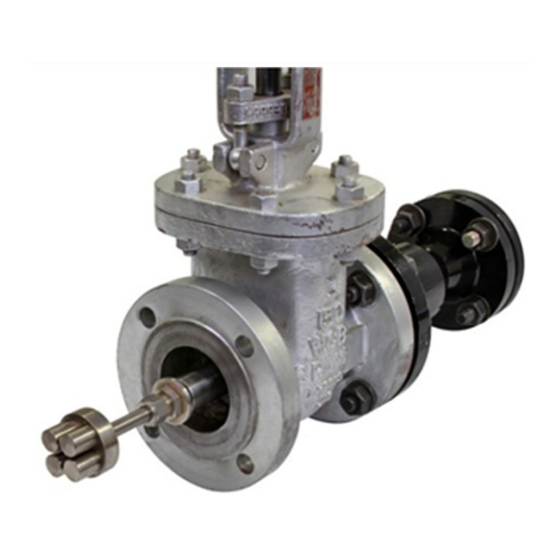
Page 63: Chapter 3. Installing An Isolation Valve
TRANSDUCER PORT GASKET 3 INCH 150 LB, RF WELDING NECK FLANGE 2 PLACES; REF ONLY 3 INCH SCH 80 PIPE NOZZLE 2 PLACES; REF ONLY FLOW GASKET DOWNSTREAM TRANSDUCER PORT Figure 66: Standard Isolation Valve Installation Model T17 Installation Guide... - Page 64 Chapter 3. Installing an Isolation Valve [no content intended for this page] Model T17 Installation Guide...
-
Page 65: Chapter 4. Inserting T17 Transducers Into The Pipe
Introduction The T17 transducer is typically installed into a meter body, which is a section of pipe that contains the ports where the transducers will be mounted. The meter body may be prefabricated or created by installing ports on the existing pipe. -
Page 66: Mounting The Insertion Mechanism
Chapter 4. Inserting T17 Transducers into the Pipe 4.2.2 Mounting the Insertion Mechanism To mount the insertion mechanism, complete the following steps: 1. Refer to Figure 67 below to familiarize yourself with the following insertion mechanism components: • Junction box •... - Page 67 Chapter 4. Inserting T17 Transducers into the Pipe 4.2.2 Mounting the Insertion Mechanism (cont.) ®1 2. Visually inspect the transducer to make sure the top Swagelok fitting is not loose (see Figure 68 below). The stop ring at the end of the barrel is supposed to be loose.
- Page 68 Chapter 4. Inserting T17 Transducers into the Pipe 4.2.2 Mounting the Insertion Mechanism (cont.) 4. Retract the barrel from the packing gland so that the transducer head is recessed in the packing gland (see Figure 69 below). You will hear the stop ring click when the transducer is fully recessed.
- Page 69 Chapter 4. Inserting T17 Transducers into the Pipe 4.2.2 Mounting the Insertion Mechanism (cont.) 6. Lift the gasket and insert the packing tool into the packing nut. By turning the packing tool clockwise, tighten the packing material so that the barrel stays up without support (see Figure 70 below).
- Page 70 Chapter 4. Inserting T17 Transducers into the Pipe 4.2.2 Mounting the Insertion Mechanism (cont.) 8. Identify the upstream and downstream transducer assemblies. For Standard Velocity Range applications, the upstream and downstream nozzle designations are interchangeable because the system is bi-directional.
- Page 71 Chapter 4. Inserting T17 Transducers into the Pipe 4.2.2 Mounting the Insertion Mechanism (cont.) 10. Lift the insertion mechanism by the barrel and place the insertion mechanism on the isolation valve (see Figure 73 below). Barrel Isolation Bolts Valve Figure 73: Place Insertion Mechanism on Isolation Valve 11.
- Page 72 Chapter 4. Inserting T17 Transducers into the Pipe 4.2.2 Mounting the Insertion Mechanism (cont.) 12. Using the packing tool, tighten the packing nut again until the nut is recessed. The packing material must be properly compressed before the isolation valve is opened.
-
Page 73: Aligning The Downstream Transducer For Extended Range Installations
Chapter 4. Inserting T17 Transducers into the Pipe 4.2.3 Aligning the Downstream Transducer for Extended Range Installations For extended velocity range applications, the head of the downstream transducer is angled at 6° so that it points upstream (into the flow) by 6°. This allows the ultrasonic signal to be pushed into alignment at very high flow rates. At low flow rates, the beam is wide enough to tolerate the initial 6°... - Page 74 Chapter 4. Inserting T17 Transducers into the Pipe 4.2.3 Aligning the Downstream Transducer (cont.) 3. The primary method for ensuring that the angled transducer head is pointing in the correct direction uses the alignment marks on the downstream nozzle and the downstream Barrel assembly (see Figure 76 below). The alignment marking on the flange at the top of the Barrel must be in alignment with the nozzle, such that the marking falls between the bolt holes straddling the upstream to downstream centerline, as shown below.
- Page 75 Chapter 4. Inserting T17 Transducers into the Pipe 4.2.3 Aligning the Downstream Transducer (cont.) 4. Before proceeding, verify that the valve and insertion mechanism are fully bolted in place (see Figure 77 below). Each stud should extend far enough beyond its nut to allow the alignment tool to rest on the stud. Fit the alignment fixture over the nozzle studs so that the two studs straddling the centerline on the nozzle are inserted into the holes on the fixture of the corresponding flange size and rating (3”, 150# or 300#).
- Page 76 Chapter 4. Inserting T17 Transducers into the Pipe 4.2.3 Aligning the Downstream Transducer (cont.) 8. Place the alignment fixture over the two studs in the flange at the top of the barrel assembly, and rotate the barrel flange until the bubble aligns between the tick marks on the vial (see Figure 79 below). Slowly press the flange toward the insertion mechanism flange until the gasket and raised faces of both flanges are mated.
-
Page 77: Connecting An Xamp
Chapter 4. Inserting T17 Transducers into the Pipe Connecting an XAMP This section explains how to correctly install and assemble an into a transducer junction box. Although one type XAMP of junction box is used as an example in the steps below, the procedure applies to all three possible junction box options (see drawing #752-063 in Figure 88 on page 73). - Page 78 Chapter 4. Inserting T17 Transducers into the Pipe 4.3 Connecting an XAMP (cont.) With the transducer and the cable gland assembled, the junction box should now look like Figure 82 below: Figure 82: Assembled Transducer and Cable Gland 5. Connect the right-angle male BNC plug to the exposed BNC cable from the cable gland assembly, as shown in Figure 83 below.
- Page 79 Chapter 4. Inserting T17 Transducers into the Pipe 4.3 Connecting an XAMP (cont.) 6. Connect the female BNC plug of the XAMP to the male BNC transducer head, as shown in Figure 84 below: Figure 84: Female Plug to Male BNC Head 7.
- Page 80 Chapter 4. Inserting T17 Transducers into the Pipe 4.3 Connecting an XAMP (cont.) 8. Place the body into the junction box (see Figure 86 below), resting the puck gently on the cables below XAMP it. Ensure that the cables of the...
- Page 81 Chapter 4. Inserting T17 Transducers into the Pipe 4.3 Connecting an XAMP (cont.) Figure 88: Transducer General Arrangement (dwg. #752-063, rev. L) Model T17 Installation Guide...
- Page 82 Chapter 4. Inserting T17 Transducers into the Pipe [no content intended for this page] Model T17 Installation Guide...
-
Page 83: Chapter 5. Maintaining The T17 Transducers
Maintaining the T17 Transducers Removing Transducers After the transducers are properly installed into the pipe nozzles as described in Chapter 4.“Inserting T17 Transducers into the Pipe”, the T17 transducers require no additional adjustments. Periodic inspection of the installation to verify the torque on the mounting bolts may be required, if erratic flow rate measurements are observed. - Page 84 Chapter 5. Maintaining the T17 Transducers 5.2 Using the Insertion Mechanism (cont.) 3. On the insertion mechanism, remove the bolts that fasten the barrel flange to the packing gland flange (see Figure 89 below). Bolts Figure 89: Removing the Bolts 4.
- Page 85 Chapter 5. Maintaining the T17 Transducers 5.2 Using the Insertion Mechanism (cont.) 5. CLOSE THE ISOLATION VALVE! Make sure the isolation valve is closed before performing the following steps. WARNING! 6. After closing the isolation valve, remove the bolts that fasten the packing gland flange to the isolation valve flange, and lift the insertion mechanism by the barrel to remove it from the isolation valve.
- Page 86 Chapter 5. Maintaining the T17 Transducers 5.2 Using the Insertion Mechanism (cont.) 7. Install a new flange gasket on the isolation valve. Then, fasten a “blind” flange onto the isolation valve with the bolts removed in the previous step (see Figure 92 below).
-
Page 87: Chapter 6. Specifications
Chapter 6. Specifications Chapter 6. Specifications T17 Transducer Physical Specifications Applications: Hazardous Area applications, Flare Gas, Hydrocarbon Gases using GE ultrasonic flow meter Models GF868 and XGF868i Installation Type: Wetted Materials of Construction: Standard: Titanium Optional: 316 Stainless Steel, Monel... - Page 88 Chapter 6. Specifications [no content intended for this page] Model T17 Installation Guide...
- Page 89 RETURN AUTHORIZATION NUMBER (RAN), and shipping instructions for the return of the instrument to a service center will be provided. 2. If GE Sensing instructs you to send your instrument to a service center, it must be shipped prepaid to the authorized repair station indicated in the shipping instructions.
- Page 90 Warranty [no content intended for this page] Model T17 Installation Guide...
- Page 91 Billerica, MA 01821 declare under our sole responsibility that the Models T3, T5, T8, T11, T14 and T17 Wetted Ultrasonic Flow Transducers Series BWT1 / F...PA / XAMP... Ultrasonic Flowmeter Transducer Assembly to which this declaration relates, are in conformity with the following standards: •...
- Page 94 Customer Support Centers U.S.A. The Boston Center 1100 Technology Park Drive Billerica, MA 01821 U.S.A. Tel: 800 833 9438 (toll-free) 978 437 1000 E-mail: [email protected] Ireland Sensing House Shannon Free Zone East Shannon, County Clare Ireland Tel: +353 61 61470200 E-mail: [email protected] An ISO 9001-2008 Certified Company www.gemeasurement.com/quality-certifications...