Siemens SIMATIC S7-1500 Manual
Digital output module
Hide thumbs
Also See for SIMATIC S7-1500:
- Function manual (402 pages) ,
- System manual (393 pages) ,
- Manual (188 pages)
Table of Contents
Quick Links
Table of Contents

Related Manuals for Siemens SIMATIC S7-1500


Summary of Contents for Siemens SIMATIC S7-1500
- Page 2 ___________________ Preface ___________________ Documentation guide ___________________ SIMATIC Product overview ___________________ Wiring S7-1500/ET 200MP DQ 8x24VDC/2A HF ___________________ Digital Output Module Parameters/address space (6ES7522-1BF00-0AB0) ___________________ Interrupts/diagnostics alarms Manual ___________________ Technical specifications ___________________ Dimensional drawing ___________________ Parameter data records 06/2018 A5E03485650-AF...
- Page 3 Note the following: WARNING Siemens products may only be used for the applications described in the catalog and in the relevant technical documentation. If products and components from other manufacturers are used, these must be recommended or approved by Siemens. Proper transport, storage, installation, assembly, commissioning, operation and maintenance are required to ensure that the products operate safely and without any problems.
-
Page 4: Preface
Purpose of the documentation This manual supplements the system manual S7-1500/ET 200MP (https://support.industry.siemens.com/cs/ww/en/view/59191792). Functions that relate in general to the systems are described in this system manual. The information provided in this manual and in the system/function manuals supports you in commissioning the systems. - Page 5 Siemens' products and solutions undergo continuous development to make them more secure. Siemens strongly recommends that product updates are applied as soon as they are available and that the latest product versions are used. Use of product versions that are no longer supported, and failure to apply the latest updates may increase customers' exposure to cyber threats.
-
Page 6: Table Of Contents
Table of contents Preface ..............................3 Documentation guide ..........................6 Product overview ..........................10 Properties ..........................10 Functions ..........................13 2.2.1 Pulse-width modulation (PWM) ....................13 2.2.2 Switching cycle counter ......................17 Wiring ..............................19 Parameters/address space ........................21 Parameters ..........................21 4.1.1 DQ operating mode parameter .................... -
Page 7: Documentation Guide
This arrangement enables you to access the specific content you require. Basic information The System Manual and Getting Started describe in detail the configuration, installation, wiring and commissioning of the SIMATIC S7-1500 and ET 200MP systems. The STEP 7 online help supports you in the configuration and programming. Device information Product manuals contain a compact description of the module-specific information, such as properties, wiring diagrams, characteristics and technical specifications. - Page 8 Documentation guide Manual Collection S7-1500/ET 200MP The Manual Collection contains the complete documentation on the SIMATIC S7-1500 automation system and the ET 200MP distributed I/O system gathered together in one file. You can find the Manual Collection on the Internet (https://support.industry.siemens.com/cs/ww/en/view/86140384).
- Page 9 Solutions are shown in interplay with multiple components in the system - separated from the focus on individual products. You will find the application examples on the Internet (https://support.industry.siemens.com/sc/ww/en/sc/2054). TIA Selection Tool With the TIA Selection Tool, you can select, configure and order devices for Totally Integrated Automation (TIA).
- Page 10 You can find SIEMENS PRONETA on the Internet (https://support.industry.siemens.com/cs/ww/en/view/67460624). SINETPLAN SINETPLAN, the Siemens Network Planner, supports you in planning automation systems and networks based on PROFINET. The tool facilitates professional and predictive dimensioning of your PROFINET installation as early as in the planning stage. In addition, SINETPLAN supports you during network optimization and helps you to exploit network resources optimally and to plan reserves.
-
Page 11: Product Overview
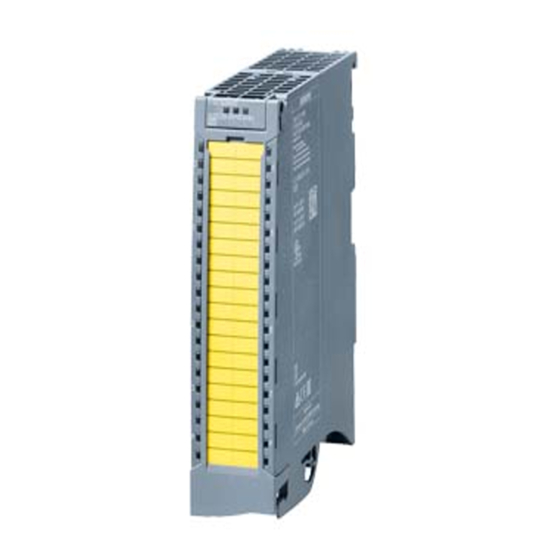
Product overview Properties Article number 6ES7522-1BF00-0AB0 View of the module Figure 2-1 View of the DQ 8x24VDC/2A HF module DQ 8x24VDC/2A HF Digital Output Module (6ES7522-1BF00-0AB0) Manual, 06/2018, A5E03485650-AF... - Page 12 Product overview 2.1 Properties Properties The module has the following technical properties: ● 8 digital outputs, electrically isolated in groups of 4 – of which optional channels 0 and 4 are available for pulse width modulation (PWM). ● Rated output voltage 24 V DC ●...
- Page 13 Other components The following component can be ordered separately: Front connectors, including potential jumpers and cable ties You can find additional information on accessories in the system manual S7-1500/ET 200MP. (https://support.industry.siemens.com/cs/ww/en/view/59191792) DQ 8x24VDC/2A HF Digital Output Module (6ES7522-1BF00-0AB0) Manual, 06/2018, A5E03485650-AF...
-
Page 14: Functions
Product overview 2.2 Functions Functions 2.2.1 Pulse-width modulation (PWM) Channels 0 and 4 of the module support the pulse width modulation (PWM) function. The pulse width modulation function can be used to easily generate periodic pulses with a constant rated voltage and a variable pulse duration for the above-mentioned channels. Advantages ●... - Page 15 Product overview 2.2 Functions How it works In the pulse width modulation mode, the two outputs (channels 0 and 4) provide one pulse width modulated output signal. Pulse width modulation is characterized by its time period (frequency) and its duty factor (also referred to as ON period or Duty Cycle ).
- Page 16 Product overview 2.2 Functions Pulse waveform The pulse duration of the actual signal profile is slightly longer than the specified, ideal pulse duration. The figure below shows the reaction of the output to control by PWM. The blue line shows the specified, ideal signal profile (square wave signal), with which the output is controlled.
- Page 17 Product overview 2.2 Functions Example for energy saving by reducing the holding current High starting current is required to activate a solenoid valve. When the solenoid valve is activated, the current requirement is lower; it only has to be held in position. This time- dependent current requirement can be met well with the PWM function.
-
Page 18: Switching Cycle Counter
Product overview 2.2 Functions 2.2.2 Switching cycle counter The function records the number of switching cycles of the output and thus the switching cycles of a connected actuator, such as those of solenoid valves. When the specified number of switching cycles is reached, the "Limit value warning" maintenance interrupt is triggered, provided it is configured and enabled. - Page 19 Product overview 2.2 Functions How it works The module counts the switching cycles by evaluating the rising edges of an output signal. If the module detects a rising edge, the switching cycle counter (24-bit) for the respective channel is incremented. After an overflow of the switching cycle counter, it starts again with If you activate the "Maintenance switching cycles"...
-
Page 20: Wiring
You can find information on wiring the front connector, establishing a cable shield, etc. in the "Wiring" section of system manual S7-1500/ET 200MP (https://support.industry.siemens.com/cs/ww/en/view/59191792). Wiring and block diagram The example in the following figure shows the terminal assignment and the assignment of the channels. - Page 21 Wiring Wiring of the outputs for channels 0 and 4 for inductive load If you set the channel 0 and channel 4 for the pulse width modulation mode, then you need to wire the outputs CH0 and CH4 with an external diode (blocking voltage U >...
-
Page 22: Parameters/Address Space
Parameters/address space Parameters DQ 8x24VDC/2A HF parameters When you assign the module parameters in STEP 7, you use various parameters to specify the module properties. The following table lists the configurable parameters. The effective range of the configurable parameters depends on the type of configuration. The following configurations are possible: ●... -
Page 23: Dq Operating Mode Parameter
Parameters/address space 4.1 Parameters 4.1.1 DQ operating mode parameter DQ 8x24VDC/2A HF parameters The table below lists the parameters in DQ mode. These parameters apply to channels 0 to Table 4- 1 Configurable parameters and their defaults Parameters Range of values Default set- Parameter Scope with configuration software,... -
Page 24: Explanation Of The Parameters Of Dq Mode
Parameters/address space 4.1 Parameters 4.1.2 Explanation of the parameters of DQ mode No supply voltage Enabling of the diagnostics, for lacking or insufficient supply voltage L+. Short circuit to ground Enabling of the diagnostics if a short-circuit of the actuator supply to ground occurs. Maintenance switching cycles You use this parameter to enable the maintenance interrupt "Limit value warning"... -
Page 25: Pulse Width Modulation Operating Mode Parameter
Parameters/address space 4.1 Parameters 4.1.3 Pulse width modulation operating mode parameter DQ 8x24VDC/2A HF parameters The table below lists the parameters in pulse width modulation mode. These parameters apply to channels 0 and 4. Table 4- 2 Configurable parameters and their defaults Parameters Range of values Default setting... -
Page 26: Explanation Of The Parameters Of Pulse Width Modulation Mode
Parameters/address space 4.1 Parameters 4.1.4 Explanation of the parameters of pulse width modulation mode Missing supply voltage Enabling of the diagnostics for missing or insufficient supply voltage L+. Short-circuit to ground Enabling of the diagnostics if a short-circuit of the actuator supply to ground occurs. Reaction to CPU STOP Determines the reaction of the output when the CPU goes into the STOP state or when the connection to the CPU is interrupted. -
Page 27: Address Space
Parameters/address space 4.2 Address space Address space The module can be configured differently in STEP 7; see following table. Depending on the configuration, additional/different addresses are assigned in the process image of the outputs/inputs. Configuration options of DQ 8x24VDC/2A HF You can configure the module with STEP 7 (TIA Portal) or with a GSD file. -
Page 28: Address Space Operating Mode Dq
Parameters/address space 4.2 Address space 4.2.1 Address space operating mode DQ Address space for configuration as 8-channel DQ 8x24VDC/2A HF The following figure shows the assignment of the address space for the configuration as a 8- channel module with value status. You can freely assign the start address for the module. The addresses of the channels are derived from the start address. - Page 29 Address space for configuration as 1 x 8-channel DQ 8x24VDC/2A HF MSO with value status Reference You can find information on the Shared Input/Output (MSI/MSO) function in the section Module-Internal Shared Input/Output (MSI/MSO) of the PROFINET with STEP 7 V13 (https://support.industry.siemens.com/cs/ww/en/view/49948856) function manual. DQ 8x24VDC/2A HF Digital Output Module (6ES7522-1BF00-0AB0) Manual, 06/2018, A5E03485650-AF...
-
Page 30: Address Space Operating Mode Pulse-Width Modulation
Parameters/address space 4.2 Address space 4.2.2 Address space operating mode pulse-width modulation Address space for configuration as 1 x 8-channel DQ 8x24VDC/2A PWM If you use the module in the "Pulse width modulation mode" (channels 0 and 4), the module uses the following address spaces: ●... -
Page 31: Interrupts/Diagnostics Alarms
Interrupts/diagnostics alarms Status and error displays LED displays The following figure shows the LED displays (status and error displays) of DQ 8x24VDC/2A HF. Figure 5-1 LED displays of the DQ 8x24VDC/2A HF module DQ 8x24VDC/2A HF Digital Output Module (6ES7522-1BF00-0AB0) Manual, 06/2018, A5E03485650-AF... - Page 32 Interrupts/diagnostics alarms 5.1 Status and error displays Meaning of the LED displays The following table explains the meaning of the status and error displays. Remedial measures for diagnostic alarms can be found in section Diagnostic alarms (Page 33). RUN and ERROR LED Table 5- 1 Status and error displays RUN and ERROR Meaning...
-
Page 33: Interrupts
Interrupts/diagnostics alarms 5.2 Interrupts LED CHx Table 5- 4 CHx status display LED CHx Meaning Solution 0 = Status of the output signal. 1 = Status of the output signal. Channel parameters assigned (channel fault Check the wiring and remedy the short-circuit pending;... -
Page 34: Diagnostics Alarms
Interrupts/diagnostics alarms 5.3 Diagnostics alarms Diagnostics alarms Diagnostics alarms A diagnostics alarm is generated and the ERROR LED flashes for each diagnostics event on the module. The diagnostics alarms can be read out in the diagnostics buffer of the CPU, for example. -
Page 35: Technical Specifications
Technical specifications Technical specifications of the DQ 8x24VDC/2A HF The following table shows the technical specifications as of 06/2018. You will find a data sheet including daily updated technical specifications on the Internet (https://support.industry.siemens.com/cs/ww/en/pv/6ES7522-1BF00-0AB0/td?dl=en). Article number 6ES7522-1BF00-0AB0 General information Product type designation... - Page 36 Technical specifications Article number 6ES7522-1BF00-0AB0 Supply voltage Rated value (DC) 24 V permissible range, lower limit (DC) 20.4 V permissible range, upper limit (DC) 28.8 V Reverse polarity protection Yes; through internal protection with 10 A per group Input current Current consumption, max.
- Page 37 Technical specifications Article number 6ES7522-1BF00-0AB0 Output current for signal "1" rated value • 2.4 A; Note derating specification for PWM opera- for signal "1" permissible range, max. • tion 0.5 mA for signal "0" residual current, max. • Output delay with resistive load 80 µs "0"...
- Page 38 Technical specifications Article number 6ES7522-1BF00-0AB0 Diagnostic messages Monitoring the supply voltage • Wire-break • Short-circuit • Group error • Diagnostics indication LED Yes; Green LED RUN LED • Yes; Red LED ERROR LED • Yes; yellow LED MAINT LED • Yes;...
- Page 39 Technical specifications Power reduction (derating) to aggregate current of outputs (per group) The following graphs show the loading capacity of the outputs in relation to the mounting position and the ambient temperature. ① Horizontal mounting of the system ② Vertical mounting of the system Figure 6-1 Details on total current of outputs (per group) DQ 8x24VDC/2A HF Digital Output Module (6ES7522-1BF00-0AB0) Manual, 06/2018, A5E03485650-AF...
- Page 40 Technical specifications DQ mode and PWM mode with switching frequency max. 100 Hz The following graphs apply to resistive loads and inductive loads with max. 2 A total current of the outputs per channel. Inductive loads in PWM mode require additional wiring to an external diode;...
- Page 41 Technical specifications PWM mode with switching frequency max. 500 Hz The following graphs apply to resistive loads and inductive loads with max. 2 A total current of the outputs per channel. Inductive loads require additional wiring with an external diode, see section Wiring (Page 19).
-
Page 42: Dimensional Drawing
Dimensional drawing The dimensional drawing of the module on the mounting rail, as well as a dimensional drawing with open front cover, are provided in the appendix. Always observe the specified dimensions for installations in cabinets, control rooms, etc. Figure A-1 Dimensional drawing of the DQ 8x24VDC/2A HF module DQ 8x24VDC/2A HF Digital Output Module (6ES7522-1BF00-0AB0) Manual, 06/2018, A5E03485650-AF... - Page 43 Dimensional drawing Figure A-2 Dimensional drawing of the DQ 8x24VDC/2A HF module, side view with open front cover DQ 8x24VDC/2A HF Digital Output Module (6ES7522-1BF00-0AB0) Manual, 06/2018, A5E03485650-AF...
-
Page 44: Parameter Data Records
Parameter data records Parameter assignment The data records of the module have an identical structure, regardless of whether you configure the module with PROFIBUS DP or PROFINET IO. Dependencies for configuration with GSD file When a GSD file is used to configure a module, dependencies can arise when "assigning the parameters". - Page 45 Parameter data records B.1 Parameter assignment Assignment of data record and channel The channel parameters of the module are included in data sets 64 to 71 and are assigned as follows: ● Data set 64 for channel 0 (PWM operating mode possible) ●...
-
Page 46: Structure Of Parameter Data Sets Ds 64 - 71
Parameter data records B.2 Structure of parameter data sets DS 64 - 71 Structure of parameter data sets DS 64 - 71 Structure of data sets 64 to 71 The figure below shows the structure of data set 64 for channel 0 as an example. The structure is identical for channels 1 to 7. -
Page 47: Structure Of Data Set Ds 129
Parameter data records B.3 Structure of data set DS 129 Structure of data set DS 129 Structure of data set 129 You can read the current states of the switching cycle counters with data set 129. The counter status is supplied for each channel in UDINT format. The following figure shows you the structure of data set 129. -
Page 48: Structure Of Data Set Ds 130
Parameter data records B.4 Structure of data set DS 130 Structure of data set DS 130 Structure of data set 130 The limits of the switching cycle counters are read out with data set 130. The set value is supplied for each channel in UDINT format. The following figure shows you the structure of data set 130. -
Page 49: Structure Of Data Set Ds 131
Parameter data records B.5 Structure of data set DS 131 Structure of data set DS 131 Structure of data set 131 The following figure shows you the structure of data set 131. Enable a parameter by setting the corresponding bit to "1". Figure B-4 Structure of data set 131: Bytes 0 to 7 DQ 8x24VDC/2A HF Digital Output Module (6ES7522-1BF00-0AB0)