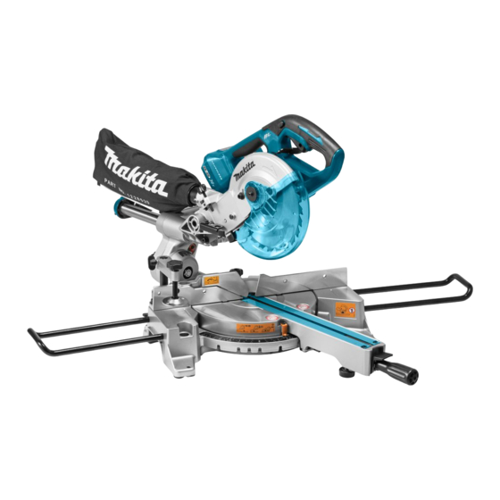
Makita DLS714 Instruction Manual
Cordless slide compound miter saw
Hide thumbs
Also See for DLS714:
- Instruction manual (188 pages) ,
- Technical information (47 pages) ,
- Instruction manual (84 pages)
Table of Contents
Quick Links
Table of Contents

Related Manuals for Makita DLS714


Summary of Contents for Makita DLS714
- Page 1 INSTRUCTION MANUAL Cordless Slide Compound Miter Saw DLS714 Read before use.
-
Page 2: Specifications
SPECIFICATIONS Model: DLS714 Blade diameter 190 mm Hole (arbor) diameter (country specific) 20 mm or 15.88 mm Max. kerf thickness of the saw blade 2.2 mm Max. miter angle Left 47°, Right 57° Max. bevel angle Left 45°, Right 5°... -
Page 3: Safety Warnings
Only for EU countries Ni-MH WARNING: The vibration emission during actual Do not dispose of electric equipment or Li-ion use of the power tool can differ from the declared val- battery pack together with household waste ue(s) depending on the ways in which the tool is used material! especially what kind of workpiece is processed. - Page 4 If operating a power tool in a damp location is unavoid- It is an employer's responsibility to enforce able, use a residual current device (RCD) protected the use of appropriate safety protective equip- supply. Use of an RCD reduces the risk of electric shock. ments by the tool operators and by other per- sons in the immediate working area.
-
Page 5: Safety Instructions For Mitre Saws
Under abusive conditions, liquid may be ejected from the battery; avoid contact. If contact acci- dentally occurs, flush with water. If liquid contacts eyes, additionally seek medical help. Liquid ejected from the battery may cause irritation or burns. Do not use a battery pack or tool that is dam- aged or modified. - Page 6 17. If the workpiece or blade becomes jammed, Use only flanges specified for this tool. turn the mitre saw off. Wait for all moving 12. Be careful not to damage the arbor, flanges parts to stop and disconnect the plug from (especially the installing surface) or bolt.
-
Page 7: Parts Description
It will also Be careful not to drop or strike battery. void the Makita warranty for the Makita tool and charger. Do not use a damaged battery. 10. The contained lithium-ion batteries are subject... -
Page 8: Installation
Slide pole (upper) Thumb screw (for lock- Hex wrench Clamp screw (for locking ing upper slide pole) holder) Lever (for bevel angle Slide pole (lower) Thumb screw (for lock- adjustment) ing lower slide pole) Turn the adjusting bolt clockwise or counterclock- INSTALLATION wise so that it comes into a contact with the floor sur- face to keep the tool stable. -
Page 9: Functional Description
Installing the holders and holder FUNCTIONAL assemblies DESCRIPTION NOTE: In some countries, the holders and holder assemblies may not be included in the tool package WARNING: Always be sure that the tool is as standard accessory. switched off and the battery cartridge is removed before adjusting or checking the functions on The holders and the holder assemblies support work- the tool. -
Page 10: Overload Protection
Tool / battery protection system Battery indicator status Remaining battery capacity The tool is equipped with a tool/battery protection sys- Blinking tem. This system automatically cuts off power to the 50% to 100% motor to extend tool and battery life. The tool will auto- matically stop during operation if the tool or battery is placed under one of the following conditions: 20% to 50%... -
Page 11: Blade Guard
Automatic speed change function Blade guard WARNING: Never defeat or remove the blade guard or the spring which attaches to the guard. An exposed blade as a result of defeated guarding may result in serious personal injury during operation. WARNING: Never use the tool if the blade guard or spring are damaged, faulty or removed. - Page 12 WARNING: Do not remove spring holding blade guard. If guard becomes damaged in course of time or UV light exposure, contact a Makita ser- vice center for replacement. DO NOT DEFEAT OR REMOVE GUARD. Positioning kerf board This tool is provided with the kerf boards in the turn base to minimize tearing on the exit side of a cut.
- Page 13 Rotate the blade by hand while holding the handle Maintaining maximum cutting all the way down to be sure that the blade does not capacity contact any part of the lower base. Re-adjust slightly, if necessary. This tool is factory adjusted to provide the maximum WARNING: After installing a new blade and cutting capacity for a 190 mm saw blade.
-
Page 14: Adjusting The Bevel Angle
Sub-fence Adjusting the bevel angle Country specific To adjust the bevel angle, loosen the lever at the rear of the tool counterclockwise. CAUTION: When performing left bevel cuts, flip the sub-fence outward. Otherwise, it may con- tact the blade or a part of the tool, and may result in serious injury to the operator. -
Page 15: Switch Action
A switch in need of repair may result in unintentional operation and seri- ous personal injury. Return tool to a Makita service center for proper repairs BEFORE further usage. WARNING: NEVER defeat the lock-off button by taping down or some other means. - Page 16 CAUTION: Use only the Makita hex wrench provided to install or remove the blade. Failure to do so may result in overtightening or insufficient tightening of the hex socket bolt. This could cause an injury.
- Page 17 Connecting a vacuum cleaner For tool with the ring When you wish to perform clean cutting operation, connect a Makita vacuum cleaner. ► 1. Outer flange 2. Saw blade 3. Inner flange 4. Hex socket bolt (left-handed) 5. Ring 6. Spindle...
-
Page 18: Securing Workpiece
Dust bag Vertical vise Optional accessory WARNING: Secure the workpiece firmly against The use of the dust bag makes cutting operations the turn base and guide fence with the vise during all cleaner and dust collection easier. operations. Otherwise the material may move during the To attach the dust bag, fit it onto the dust nozzle. -
Page 19: Operation
The horizontal vise can be installed on the left side of the base. OPERATION By turning the vise knob counterclockwise, the screw is released and the vise shaft can be moved rapidly in and out. By turning the vise knob clockwise, the screw remains secured. WARNING: Make sure the blade is not con- To grip the workpiece, turn the vise knob gently clockwise... -
Page 20: Miter Cutting
Secure the workpiece with the proper type of vise. Miter cutting Switch on the tool without the blade making any contact and wait until the blade attains full speed before Refer to the previously covered "Adjusting the miter lowering. angle". Gently lower the handle to the fully lowered posi- Bevel cut tion to cut the workpiece. -
Page 21: Compound Cutting
NOTICE: When pressing down the handle, apply pressure in parallel with the blade. If a force is applied perpendicularly to the turn base or if the pres- sure direction is changed during a cut, the precision of the cut will be impaired. Compound cutting Compound cutting is the process in which a bevel angle is made at the same time in which a miter angle... - Page 22 Table (A) When securing aluminum extrusions, use spacer blocks or pieces of scrap as shown in the figure to prevent – Molding Bevel angle Miter angle deformation of the aluminum. Use a cutting lubricant position when cutting the aluminum extrusion to prevent build-up 52/38°...
-
Page 23: Carrying Tool
Carrying tool WARNING: Stopper pin is only for carrying and storage purposes and should never be used for any cutting operations. The use of the stopper pin for cutting operations may cause unexpected movement of the saw blade resulting in kickback and serious personal injury. -
Page 24: Adjusting The Cutting Angle
Make sure that the pointer indicates 0° on the Adjusting the cutting angle miter scale. If the pointer does not indicate 0°, loosen the screw which secures the pointer and adjust the This tool is carefully adjusted and aligned at the factory, pointer so that it indicates 0°. -
Page 25: After Use
0°. These Makita accessories or attachments are recommended for use with your Makita tool specified in this manual. The use of any other accessories or attachments may result in serious personal injury. - Page 28 Makita Europe N.V. Jan-Baptist Vinkstraat 2, 3070 Kortenberg, Belgium Makita Corporation 3-11-8, Sumiyoshi-cho, Anjo, Aichi 446-8502 Japan 885680-227 www.makita.com 20180910...