Quick Links
Solar inverters
Quick installation guide
Rapid shutdown device (RSD) for 600Vdc
EN
D
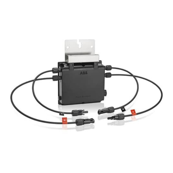
RSD - Single Channel Version
D
RSD - Dual Channel Version
FOLD
3. RSD installation location
a. Install the RSD on the roof, within ten feet of the PV array.
b. Note that the RSD may be installed at any angle from horizontal to vertical.
c. Note the temperature (-40
o
C to 75
o
C) and enclosure ratings (Type 4X) listed on product label attached to the RSD.
d. Choose a location where the maximum ambient air temperature will be less than the 75
While exposure to direct sunlight is permitted; installation under a module is preferred.
e. Ensure there is sufficient working area around the RSD to allow easy access for maintenance and/or service of the PV
system. If installing the RSD under a PV module, place it under the first or last module in a row for access. Never install
the RSD in a location that would require the removal of multiple PV modules in order to gain access.
f. Note that the RSD power supply may already be inside the photovoltaic inverter wiring box.
4. Mounting the RSD
a. The mounting bracket (A) will come attached to the RSD device. The bracket has four screw holes (B). The RSD box may
be raised or lowered to match four bracket screw holes as needed for clearance from modules or roof. If needed, adjust the
bracket, reattach the bracket to the RSD box with the four screws provided with the device, and torque to 3.5 N . m (2.6 ft-lb).
b. When mounting the RSD device to the PV module frame, use the components supplied with the racking to secure the
mounting bracket (A) to the PV module frame in the area marked (C).
Label
Description of RSD device components
A
Mounting bracket
B
Bracket mounting holes
C
RSD mounting bracket attachment points
D
Input conductor leads (coming from PV panels)
E
Output conductor leads (going to the inverter)
F
24V supply cable
Table 3
D
F
Figure 1
F
E
F
F
C specifed maximum temperature.
o
A
B
Figure 2
E
Figure 3: UNO DM+ with 24Vdc power supply
attachment points inside wire box.
1. Label and warnings
IMPORTANT SAFETY INSTRUCTIONS
followed during installation and maintenance of the RSD system.
SAVE THESE INSTRUCTIONS –
inverter for easy access during installation and maintenanc
NOTE –
This RSD has been tested and certified for use only with ABB single-phase inverters. If used with other inverters,
the RSD may not meet the rapid shutdown requirements of the NEC or perform as specified. Furthermore, use of the RSD
with any other inverters voids the RSD product warranty.
ELECTRICAL WARNINGS –
An ABB RSD system is designed to comply with the 2014 NFPA 70 National Electric Code, section 690.12 and is tested
—
according to international safety requirements (UL1741); however, certain safety precautions must be observed when
installing and operating this product. Personal protective equipment (PPE) must be worn at all times when servicing this
equipment.
Wiring methods used must be in accordance with the National Electric Code, ANSI/NFPA 70 and/or any prevailing local
—
codes and regulations.
For suitable wire sizes (AWG), refer to National Electrical Code, Table 310.15(B)(16) for U.S. applications. Use only
—
copper (Cu) wire rated for 90
This RSD operates only when properly connected to the power supply and PV strings.
—
These connections must be made only by qualified technical personnel.
—
The DC operating current and voltage MUST NOT exceed the absolute maximum limits (25A and 600Vdc).
—
The RSD system is compatible with 208V and 240V grid connections; it is not compatible with 277V connections.
—
The RSD must be tested before the system is commissioned.
—
Safety and Hazard Symbols
Risk of electrical shock. Hazardous voltage
will cause severe injury or death. No user-
serviceable parts inside. Only trained service
personnel are allowed access.
Risk of electrical shock. Multiple voltage
sources may be terminated inside this
equipment. Each circuit must be disconnected
before servicing.
Table 1
E
2. List of components and spare parts
Qty
Description
RSD2.0-1PN6-MC4 - single channel
1
RSD2.0-2PN6-MC4 - dual channel
1
24Vdc power supply
1
Mounting bracket - standard
4
Mounting screws
2
Three-position terminal blocks
Inverter power supply AC conductors
1
(Terminal 1, Terminal 2, GND)
1
Cover for three-position terminal block
1
Quick installation guide
Table 2 *kit version required for PVI-3.0/3.6/3.8/4.2/5000/6000 and UNO-7.6/8.6 inverters
5. Wiring the RSD input (from PV array) and output (to inverter)
a. Ensure the inverter's external AC disconnect and its integrated DC disconnect are turned OFF (open). Use appropriate
PPE, and use insulated tools when working with this equipment.
b. Ensure the EGC from the array is indeed connected in the inverter: The equipment grounding conductor (EGC) must
connect the inverter and array in order for the inverter's ground fault protection to operate as required. (The RSD
enclosure itself is polycarbonate and does not require bonding.)
c. Refer to local codes for appropriate wire size on all conductors.
d. Locate the input wires (D) on the side of the RSD device marked "Input". This marking is present near the edge of the
RSD device on the front and back side. Connect the RSD input wires (D) to the PV array. The positive end of the PV
array must be connected to the RSD input wire labeled (+). The negative end of the PV array must be connected to the
RSD input wire labeled (-). (Note that there will be voltage on the PV array at this point.)
e. Locate the output wires (E) on the side of the RSD device marked "Output". This marking is present near the edge of the
RSD device on the front and back side. Connect the RSD output wires (D) to the inverter inputs. The RSD output wire
labeled Inverter (+) must be connected to the positive DC input terminal of the inverter. The RSD output wire labeled
Inverter (-) must be connected to the negative DC input terminal of the inverter.
WARNING: Swapping the input and output connections of the RSD device may make the system non-compliant
and/or create a hazardous situation. Therefore extra care must be taken to ensure proper connections of the input
and output wiring of the RSD device.
6. Prepare to install the 24Vdc power supply
a. Confirm the inverter output (grid connection) is three-wire 240V line-to-line or two-wire 208V line-to-line inverter output.
C
The RSD unit is NOT compatible with a 277V grid connection. It must only be used with a 208V or 240V grid
connection.
b. Confirm all items in the RSD kit are accounted for; two 3-position terminal blocks and one terminal block cover (Figure
4), 24Vdc power supply and three short conductors to connect the power supply to the inverter AC terminals and to
ground. The 24Vdc power supply, terminal blocks, terminal cover and AC conductor cable will be be installed inside the
ABB string inverter's wiring box.
c. Before installing the 24Vdc power supply, open (turn OFF) the PV system AC disconnect switch AND the PV breaker
to ensure the inverter is disconnected from the grid and from the PV modules.
d. Follow the instructions starting in section 7 to install the 24Vdc power supply. Note that the power supply pigtail coming
out of the RSD box (FIgure 5) will house both the 24V and return wires.
e. The new UNO-DM+ inverter will already have a 24Vdc power supply inside the inverter wiring box and you can skip
sections 7 & 8. Only the older PVI-3.0/3.6/ 3.8/4.2/5000/6000-TL inverters and the UNO 7.6/8.6 inverters will require
you to add the 24Vdc power supply as described in sections 7 & 8.
Note that an uncovered terminal blocks' interior metal will carry the AC voltage. Therefore, the terminal block
cover is required to ensure there is no exposed AC voltage.
– This QIG contains important safety instructions that must be
Keep this document in a safe place near the photovoltaic (PV) system
e.
C, solid or with type B or type C stranding (19 strands minimum).
o
Verify the correct connection of the strings to the input
terminals. Polarity reversal may cause serious damage.
Refer to the appropriate product instruction manuals for
more details.
When the photovoltaic array is exposed to light, it
supplies DC voltage to this equipment.
Part Number
Included with standalone device or kit*
3P029970000C - single
Standalone device and kit
3P029950000C - dual
YPA.00238
Kit only
XER.P0500.0
Standalone device and kit
816200010FA-G
Standalone device and kit
ZEB.00273
Kit only
ZLH.P0504.0
Kit only
ZEB.00275
Kit only
BCM.00372.3DG_AA
Standalone device and kit
Figure 4

Related Manuals for ABB RSD2.0-1PN6-MC4


Summary of Contents for ABB RSD2.0-1PN6-MC4
- Page 1 RSD product warranty. ELECTRICAL WARNINGS – An ABB RSD system is designed to comply with the 2014 NFPA 70 National Electric Code, section 690.12 and is tested — according to international safety requirements (UL1741); however, certain safety precautions must be observed when installing and operating this product.
- Page 2 However, each 24Vdc power supply in the kit can power up to six single-output RSDs (ABB P/N: RS1-1PN6-MC4) or three dual-input RSDs (ABB P/N: RS2-2PN6-MC4). For more than two RSDs, you must use an UL approved "I" or "T" splice or a Contact us BCM.00372.3DG Rev AA...