Quick Links
Doc. N.° 1SDH002033A1001 - ECN000117970 - Rev. D
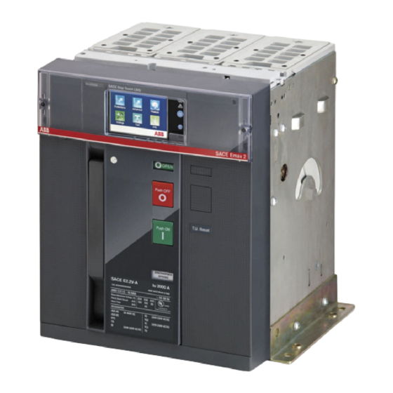
Emax 2
Kit terminali per adattamento interruttori
Terminals kit to match Entelliguard G Env 1
Kit Anschlüsse für Anpassung Steckbarer Leistungsschaltern
Kit prises pour l'adaptation disjoncteurs Débrochables
Kit terminales para la adaptación interruptores Extraíble
Il presente kit di terminali, consente la sostituzione totale di interruttori
aperti Entelliguard G Envelope 1, Envelope 2 e Envelope 3 con interruttori
aperti in esecuzione estraibile di più moderna fattura tipo Emax 2
di medesima taglia, senza dover eseguire alcuna modifica alle parti attive
del quadro.
E' garantita la totale corrispondenza delle caratteristiche elettriche (corrente
nominale e potere di interruzione) a condizione che
1.La scelta sia effettuata in conformità a quanto riportato nei cataloghi tecnici
relativi ai prodotti.
2.L'interruttore Entelliguard G Envelope 1, Envelope 2, Envelope 3
da sostituire sia installato in conformità al proprio manuale di installazione,
rispettando le distanze di isolamento verso massa, il dimensionamento delle
sbarre di connessione, il posizionamento del primo setto di ancoraggio.
IMPORTANTE
Questi terminali consentono la sostituzione di un dispositivo di comando
e protezione divenuto obsoleto ma non di alterare in maniera alcuna i dati di
progetto originali del quadro esistente. Qualora il nuovo interruttore
presentasse dati di targa superiori, i terminali sono dimensionati per le
prestazioni del vecchio dispositivo.
Per ulteriori chiarimenti contattare ABB.
Attenzione Istruzioni riguardanti il solo assemblaggio del kit terminali,
non sono da intendersi come sostitutive del manuale di installazione, uso e
manutenzione del nuovo interruttore Emax
L'uso di questi terminali Emax 2 per sostituzione di Entelliguard G non è
stata valutata da UL.
MESSA IN SICUREZZA DELL'IMPIANTO
A) A garanzia dell'incolumità del personale addetti all'installazione del kit,
prima di operare la sostituzione dell'interruttore, si raccomanda di seguire,
scrupolosamente, le seguenti azioni:
- Mettere fuori servizio il quadro ospitante
- Portare l'interruttore da sostituire in posizione di aperto e molle scariche
- Disconnettere le applicazioni ausiliarie
- Prima di estrarre l'apparecchio, controllare nuovamente il fuori servizio
dell'utenza
B) Smantellare completamente il vecchio interruttore conservando le viti di
connessione dei poli del vecchio interruttore Entelliguard G Envelope 1,
Envelope 2, Envelope 3 alla barratura del quadro.
,
Estraibili Entelliguard G Env 1
,
Env 2, Env 3 to Emax 2 E2.2-A, E4.2-A, E6.2-A Withdrawable circuit breakers
Entelliguard G Env 1
Entelliguard G Env 1
Entelliguard G Env 1
2.
Env 2, Env 3 ad Emax 2 E2.2-A, E4.2-A, E6.2-A
,
Env 2, Env 3 an Emax 2 E2.2-A, E4.2-A, E6.2-A
,
Env 2, Env 3 à Emax 2 E2.2-A, E4.2-A, E6.2-A
,
Env 2, Env 3 a Emax 2 E2.2-A, E4.2-A, E6.2-A
This terminals kit allows Env1 Env2 Env3 (Entelliguard G) circuit-breakers
to be fully replaced with the more modern Emax 2
plug-in air circuit-breakers of the same size without having to modify the live
parts of the switchgear in any way.
Full correspondence of the electrical characteristics is guaranteed (rated
current and breaking capacity) so long as:
1.The kit is chosen in accordance with the indications in the technical
catalogues dedicated to products.
2.The Env1 Env2 Env3 (Entelliguard G) circuit-breaker to be replaced has
been installed in compliance with the instructions in the relative installation
manual, and with the specified insulation clearance towards earth, connection
busbar size and position of the first anchor plate.
IMPORTANT
Terminals allow an obsolete control and protection device to be replaced,
but does not allow the data of the original project of the existing switchboard
to be altered in any way.
If the rating plate data of the new circuit-breaker are higher, the terminals
kits are sized for the performance of the old device.
Consult ABB for further details.
Warning The instructions concern the sole assembly of the terminals kit.
They do not substitute the instructions in the installation, operation and
maintenance manual of the new Emax 2 circuit-breaker.
Use of these Emax 2 terminals for replacement of Entelliguard G has not
been evaluated by UL.
SETTING THE INSTALLATION IN SAFE CONDITIONS
A) To ensure that the persons who install the kit work in safe conditions,
strictly comply with the following instructions before replacing the
the circuit breaker.
- Close down the switchboard in which the circuit-breaker is to be installed.
- Set the old circuit-breaker to the open position with the springs unloaded.
- Disconnect the auxiliary circuit applications.
- Check to make sure that the user is disconnected before removing the
device.
B) Completely disassemble the old circuit-breaker, but keep the screws that
connect the poles of the old Env 1 Env 2 Env 3 (Entelliguard G)
circuit-breaker to the switchboard bars.

Related Manuals for ABB Emax 2


Summary of Contents for ABB Emax 2
- Page 1 Env 2, Env 3 ad Emax 2 E2.2-A, E4.2-A, E6.2-A Terminals kit to match Entelliguard G Env 1 Env 2, Env 3 to Emax 2 E2.2-A, E4.2-A, E6.2-A Withdrawable circuit breakers Kit Anschlüsse für Anpassung Steckbarer Leistungsschaltern Entelliguard G Env 1 Env 2, Env 3 an Emax 2 E2.2-A, E4.2-A, E6.2-A...
- Page 2 Typ Emax 2 der gleichen Baugröße conception plus moderne type Emax 2 de tipo Emax 2, del mismo tamaño, sin tener que auszutauschen, ohne irgendeine Änderung an même taille, sans devoir effectuer aucune modificar ninguna parte activa del cuadro.
- Page 3 RF Env1(S)-W 1200 VR 3p->E2.2(S)-A 1200 M8X16 M6X20 RF Env1(N,H,P)-W 1600 VR 3p->E2.2(S,H,V)-A 1600 M8X16 M6X20 RF Env1(N,H,P)-W 2000 VR 3p->E2.2(S,H,V)-A 2000 M6X20 M8x16 RF Env2(E,M)-W 1600 VR 3p->E4.2(H,V)-A 1600 M8X16 M8X22...
- Page 4 RF Env2(E,M)-W 2000 VR 3p->E4.2(H,V)-A 2000 M8X16 M8X22 RF Env2(N,H,M)-W 2500 VR 3p->E4.2(S,H,V)-A 2500 M8X16 M8X22 RF Env2(N,E,M)-W 3200 VR 3p->E4.2(H,V)-A 3200 M8X16 M8X22 RF Env3-W 5000 VR 3p->E6.2-A 5000 M8X16 M8X22...
- Page 5 RF Env1(S)-W 1200 VR 3p->E2.2-A 1200 - Installare i terminali sulla parte fissa - Install the terminals on the fixed part - Installieren Sie die Klemmen am Festes Teil - Installer les prises sur la partie xe - Instale los terminales a la parte ja TERMINALE SUPERIORE UPPER TERMINAL OBERE ANSCHLUSS...
- Page 6 RF Env1(S)-W 1200 VR 3p->E2.2-A 1200 - Installare i supporti nel quadro. Stringere le viti. - Install the supports in the switchboard. Tighten the screws. - Installieren Sie die Stützen in die Schaltanlage. Ziehen Sie die Schrauben an. - Installez les supports dans le tableau. Serrez les vis. - Instale los soportes en el cuadro.
- Page 7 RF Env1(N,H,P)-W 1600 VR 3p->E2.2-A 1600 - Installare le piastre di adattamento sull’interruttore. - Install the Adapter plates to the breaker. - Installieren Sie die Adapterplatten am Leistungsschalter. - Installer les plaques d’adaptateur sur le disjoncteur - Instale las placas adaptadoras en el interruptor. 8.5Nm(75 lb-in) RF Env1(N,H,P)-W 1600 VR 3p->E2.2-A 1600 TERMINALE SUPERIORE...
- Page 8 RF Env1(N,H,P)-W 1600 VR 3p->E2.2-A 1600 - Installare i supporti nel quadro. Stringere le viti. - Install the supports in the switchboard. Tighten the screws. - Installieren Sie die Stützen in die Schaltanlage. Ziehen Sie die Schrauben an. - Installez les supports dans le tableau. Serrez les vis. - Instale los soportes en el cuadro.
- Page 9 RF Env1(N,H,P)-W 2000 VR 3p->E2.2-A 2000 - Installare le piastre di adattamento sull’interruttore. - Install the Adapter plates to the breaker. - Installieren Sie die Adapterplatten am Leistungsschalter. - Installer les plaques d’adaptateur sur le disjoncteur - Instale las placas adaptadoras en el interruptor. 8.5Nm (75 lb-in) RF Env1(N,H,P)-W 2000 VR 3p->E2.2-A 2000 TERMINALE SUPERIORE...
- Page 10 RF Env1(N,H,P)-W 2000 VR 3p->E2.2-A 2000 - Installare i supporti nel quadro. Stringere le viti. - Install the supports in the switchboard. Tighten the screws. - Installieren Sie die Stützen in die Schaltanlage. Ziehen Sie die Schrauben an. - Installez les supports dans le tableau. Serrez les vis. - Instale los soportes en el cuadro.
- Page 11 RF Env2(E,M)-W 1600 VR 3p->E4.2-A 1600 - Installare i terminali sulla parte fissa - Install the terminals on the fixed part - Installieren Sie die Klemmen am Festes Teil - Installer les prises sur la partie xe - Instale los terminales a la parte ja TERMINALE SUPERIORE UPPER TERMINAL OBERE ANSCHLUSS...
- Page 12 RF Env2(E,M)-W 1600 VR 3p->E4.2-A 1600 - Installare i supporti nel quadro. Stringere le viti. - Install the supports in the switchboard. Tighten the screws. - Installieren Sie die Stützen in die Schaltanlage. Ziehen Sie die Schrauben an. - Installez les supports dans le tableau. Serrez les vis. - Instale los soportes en el cuadro.
- Page 13 RF Env2(E,M)-W 2000 VR 3p->E4.2-A 2000 - Installare i terminali sulla parte fissa - Install the terminals on the fixed part - Installieren Sie die Klemmen am Festes Teil - Installer les prises sur la partie xe - Instale los terminales a la parte ja TERMINALE SUPERIORE UPPER TERMINAL OBERE ANSCHLUSS...
- Page 14 RF Env2(E,M)-W 2000 VR 3p->E4.2-A 2000 - Installare i supporti nel quadro. Stringere le viti. - Install the supports in the switchboard. Tighten the screws. - Installieren Sie die Stützen in die Schaltanlage. Ziehen Sie die Schrauben an. - Installez les supports dans le tableau. Serrez les vis. - Instale los soportes en el cuadro.
- Page 15 RF Env2(N,H,M)-W 2500 VR 3p->E4.2-A 2500 TERMINALE SUPERIORE UPPER TERMINAL OBERE ANSCHLUSS BORNE SUPÉRIEURE TERMINALES SUPERIOR 20.5Nm(181 lb-in) - Installare i terminali sulla parte fissa - Install the terminals on the fixed part - Installieren Sie die Klemmen am Festes Teil - Installer les prises sur la partie xe - Instale los terminales a la parte ja TERMINALE INFERIORE...
- Page 16 RF Env2(N,H,M)-W 2500 VR 3p->E4.2-A 2500 - Installare i supporti nel quadro. Stringere le viti. - Install the supports in the switchboard. Tighten the screws. - Installieren Sie die Stützen in die Schaltanlage. Ziehen Sie die Schrauben an. - Installez les supports dans le tableau. Serrez les vis. - Instale los soportes en el cuadro.
- Page 17 RF Env2(N,E,M)-W 3200 VR 3p->E4.2-A 3200 TERMINALE SUPERIORE UPPER TERMINAL OBERE ANSCHLUSS BORNE SUPÉRIEURE TERMINALES SUPERIOR 20.5Nm(181 lb-in) - Installare i terminali sulla parte fissa - Install the terminals on the fixed part - Installieren Sie die Klemmen am Festes Teil - Installer les prises sur la partie xe TERMINALE INFERIORE - Instale los terminales a la parte ja...
- Page 18 - Installare i supporti nel quadro. Stringere le viti. RF Env2(N,E,M)-W 3200 VR 3p->E4.2-A 3200 - Install the supports in the switchboard. Tighten the screws. - Installieren Sie die Stützen in die Schaltanlage. Ziehen Sie die Schrauben an. - Installez les supports dans le tableau. Serrez les vis. - Instale los soportes en el cuadro.
- Page 19 RF Env3-W 5000 VR 3p->E6.2-A 5000 - Installare le piastre di adattamento sull’interruttore. - Install the Adapter plates to the breaker. - Installieren Sie die Adapterplatten am Leistungsschalter. - Installer les plaques d’adaptateur sur le disjoncteur - Instale las placas adaptadoras en el interruptor. 20.5Nm(181 lb-in) RF Env3-W 5000 VR 3p->E6.2-A 5000 TERMINALE SUPERIORE...
- Page 20 RF Env3-W 5000 VR 3p->E6.2-A 5000 - Installare i supporti nel quadro. Stringere le viti. - Install the supports in the switchboard. Tighten the screws. - Installieren Sie die Stützen in die Schaltanlage. Ziehen Sie die Schrauben an. - Installez les supports dans le tableau. Serrez les vis. - Instale los soportes en el cuadro.
- Page 21 Entelliguard G-ENV.1 / EMAX 2.2-A 3Pole - Forare la portella quadro secondo necessità del nuovo interruttore. Controllare il posizionamento degli assi. Per maggiori informazioni vedi 1SDH001000R0728 - Make a hole in the switchboard door to suit the new circuit-breaker. Check the positions of the axes.
- Page 22 Contrôler le positionnement des axes. Pour plus d’informations, voir 1SDH001000R0728. - Perforar la puerta del cuadro según las exigencias - Asse foratura porta Emax 2 - Emax 2 door aperture axis impuestas por el nuevo interruptor. Controlar la - Bohrachse der Tür Emax 2...
- Page 23 Für nähere Informationen siehe 1SDH001000R0728. - Percer la porte du tableau d’après les exigences du nouveau disjoncteur. Contrôler le positionnement des axes. - Asse foratura porta Emax 2 Pour plus d’informations, voir 1SDH001000R0728. - Emax 2 door aperture axis - Perforar la puerta del cuadro según las exigencias - Bohrachse der Tür Emax 2...
- Page 24 Effectuer des essais à vide pour la vérication des circuits auxiliaires. Efectuar pruebas sin carga para vericar los circuitos auxiliares. Seguire le istruzioni di messa in servizio del nuovo interruttore secondo il manuale di installazione uso e manutenzione Emax 2 1SDH001000R0001.