Huawei MC509 Series Hardware Manual
Cdma lga module
Hide thumbs
Also See for MC509 Series:
- Hardware manual (57 pages) ,
- Hardware migration manual (70 pages) ,
- Development kit manual (35 pages)
Table of Contents
Quick Links
Table of Contents

Related Manuals for Huawei MC509 Series


Summary of Contents for Huawei MC509 Series
- Page 1 HUAWEI MC509 Series CDMA LGA Module Hardware Guide Issue Date 2013-05-06...
- Page 2 E-mail: [email protected] Please refer color and shape to product. Huawei reserves the right to make changes or improvements to any of the products without prior notice. Copyright © Huawei Technologies Co., Ltd. 2013. All rights reserved. No part of this document may be reproduced or transmitted in any form or by any means without prior written consent of Huawei Technologies Co., Ltd.
- Page 3 HUAWEI MC509 Series CDMA LGA Module Hardware Guide About This Document About This Document Revision History Document Date Chapter Descriptions Version 2011-07-04 Creation 2013-05-06 Updated Table 2-1 Feature Updated Figure 2-1 Circuit block diagram of the MC509 module Updated Figure 2-2 Application block...
- Page 4 HUAWEI MC509 Series CDMA LGA Module Hardware Guide About This Document Summary This document provides information about the major functions, supported services, system architecture, and technical references of HUAWEI MC509 CDMA LGA Module. The following table lists the contents of this document. Chapter Details...
-
Page 5: Table Of Contents
HUAWEI MC509 Series CDMA LGA Module Hardware Guide Content Content 1 Introduction............................ 8 2 Overall Description ........................9 2.1 About This Chapter ........................... 9 2.2 Function Overview..........................9 2.3 Circuit Block Diagram ........................11 2.4 Application Block Diagram ......................12 3 Description of the Application Interfaces ................ - Page 6 HUAWEI MC509 Series CDMA LGA Module Hardware Guide Content 3.12 Reserved Interface ........................44 3.13 NC Interface ..........................44 4 RF Specifications ......................... 45 4.1 About This Chapter ......................... 45 4.2 Antenna Installation Guidelines ...................... 45 4.3 Operating Frequencies ........................45 4.4 Conducted RF Measurement ......................
- Page 7 HUAWEI MC509 Series CDMA LGA Module Hardware Guide Content 6.9.1 General Description of Assembly Processes ................ 66 6.9.2 Stencil Design ........................66 6.9.3 Reflow Profile ........................67 6.10 Specification of Rework ........................ 69 6.10.1 Process of Rework ......................69 6.10.2 Preparations of Rework ....................... 69 6.10.3 Removing of the Module .....................
-
Page 8: Introduction
Introduction This document describes the hardware application interfaces and air interfaces that are provided when the HUAWEI MC509 CDMA LGA Module (hereinafter referred to as the MC509 module) is used. This document helps you to understand the interface specifications, electrical features, and related product information of the MC509 module. -
Page 9: Overall Description
HUAWEI MC509 Series CDMA LGA Module Hardware Guide Overall Description Overall Description 2.1 About This Chapter This chapter gives a general description of the MC509 module and provides: Function Overview Circuit Block Diagram Application Block Diagram 2.2 Function Overview... - Page 10 HUAWEI MC509 Series CDMA LGA Module Hardware Guide Overall Description Feature Description AT Commands See the HUAWEI MC509 CDMA LGA Module AT Command Interface Specification. Application Universal Asynchronous Receiver-Transmitter (UART) Interface (145- Supporting 8-wire UART pin LGA interface) One standard Removable User Identity Module (RUIM) card (3 V or 1.8 V)
-
Page 11: Circuit Block Diagram
HUAWEI MC509 Series CDMA LGA Module Hardware Guide Overall Description [1]:The temperatures outside of the range –20° C to +70° C; the module might slightly deviate from 3GPP2 C.S057D specifications. 2.3 Circuit Block Diagram Figure 2-1 shows the circuit block diagram of the MC509 module. The application... -
Page 12: Application Block Diagram
HUAWEI MC509 Series CDMA LGA Module Hardware Guide Overall Description 2.4 Application Block Diagram Figure 2-2 Application block diagram of the MC509 module UART Interface: The module supports 8-wire UART. USB Interface: The USB interface supports USB 2.0 full speed standard. -
Page 13: Description Of The Application Interfaces
The MC509 module uses a 145-pin LGA as its external interface. For details about the module and dimensions of the LGA, see “6.4 Dimensions and interfaces”. If DTE supports Huawei LGA module, such as module with system of CDMA, you can refer to Huawei LGA Module Migration Guide to get the details. - Page 14 HUAWEI MC509 Series CDMA LGA Module Hardware Guide Description of the Application Interfaces Table 3-1 Definitions of pins on the LGA interface Pin Name Description DC Characteristics (V) Normal Min. Typ. Max. Not connected, please keep this pin open Not connected, please keep this...
- Page 15 HUAWEI MC509 Series CDMA LGA Module Hardware Guide Description of the Application Interfaces Pin Name Description DC Characteristics (V) Normal Min. Typ. Max. Not connected, please keep this pin open Not connected, please keep this pin open Not connected, please keep this...
- Page 16 HUAWEI MC509 Series CDMA LGA Module Hardware Guide Description of the Application Interfaces Pin Name Description DC Characteristics (V) Normal Min. Typ. Max. MIC1_P (Only telematics version supports audio function , Data only version does not support this function) Positive pole of the input of audio...
- Page 17 HUAWEI MC509 Series CDMA LGA Module Hardware Guide Description of the Application Interfaces Pin Name Description DC Characteristics (V) Normal Min. Typ. Max. Not connected, please keep this pin open Not connected, please keep this pin open Not connected, please keep this...
- Page 18 HUAWEI MC509 Series CDMA LGA Module Hardware Guide Description of the Application Interfaces Pin Name Description DC Characteristics (V) Normal Min. Typ. Max. Not connected, please keep this pin open Not connected, please keep this pin open USB_DM Full-speed USB D-...
- Page 19 HUAWEI MC509 Series CDMA LGA Module Hardware Guide Description of the Application Interfaces Pin Name Description DC Characteristics (V) Normal Min. Typ. Max. SPKR_OUT_N (Only telematics version supports audio function, Data only version does not support this function) Negative pole of the output of speaker interface –0.3...
- Page 20 HUAWEI MC509 Series CDMA LGA Module Hardware Guide Description of the Application Interfaces Pin Name Description DC Characteristics (V) Normal Min. Typ. Max. Not connected, please keep this pin open Thermal Ground Pad Thermal Ground Pad Thermal Ground Pad Thermal Ground Pad...
- Page 21 HUAWEI MC509 Series CDMA LGA Module Hardware Guide Description of the Application Interfaces P indicates power pins; I indicates pins for digital signal input; O indicates pins for digital signal output. AI indicates pins for analog signal input; AO indicates pins for analog signal output.
-
Page 22: Power Interface
HUAWEI MC509 Series CDMA LGA Module Hardware Guide Description of the Application Interfaces Figure 3-1 Bottom view of sequence of LGA interface pins 3.3 Power Interface 3.3.1 Overview The power supply part of the MC509 module contains: VBAT pins for the power supply ... -
Page 23: Vbat Interface
HUAWEI MC509 Series CDMA LGA Module Hardware Guide Description of the Application Interfaces Table 3-2 lists the definitions of the pins on the power supply interface. Table 3-2 Definitions of the pins on the power supply interface Pin No. Signal... -
Page 24: Output Power Supply Interface
HUAWEI MC509 Series CDMA LGA Module Hardware Guide Description of the Application Interfaces Figure 3-2 Recommended power circuit of MC509 module Module (DCE) VBAT VBAT 10 μF 220 μF 100 nF 3.3.3 Output Power Supply Interface Output Power Supply Interface includes VCC_EXT1 pin and VCC_EXT2 pin. -
Page 25: Input Signal Control Pins
HUAWEI MC509 Series CDMA LGA Module Hardware Guide Description of the Application Interfaces Table 3-3 Pins on the signal control interface Pin Name Description DC Characteristics (V) Min. Typ. Max. POWER_ON_OFF Pin for controlling power-on and Pulled up on power-off chip –0.3... - Page 26 HUAWEI MC509 Series CDMA LGA Module Hardware Guide Description of the Application Interfaces As the RESIN_N and POWER_ON_OFF signals are relatively sensitive, it is recommended that you install a 10 nF capacitor near the RESIN_N and POWER_ON_OFF pins of the interface for filtering. In addition, when you design a circuit on the interface board, it is recommended that the circuit length not exceed 20 mm and that the circuit be kept at a distance of 2.54 mm (100 mil) at least from the...
- Page 27 HUAWEI MC509 Series CDMA LGA Module Hardware Guide Description of the Application Interfaces Figure 3-4 Power on timing sequence Table 3-4 Power on timing Parameter Comments Time(Nominal values) Units POWER_ON_OFF turn on time. 0.5< T <1 POWER_ON_OFF Valid to USB...
- Page 28 HUAWEI MC509 Series CDMA LGA Module Hardware Guide Description of the Application Interfaces Table 3-5 Power off timing Parameter Comments Time(Nominal values) Units POWER_ON_OFF turn off time. 3< T <4 POFF POFF POWER_ON_OFF Valid to USB about 4 D+ high...
-
Page 29: Output Signal Control Pin
HUAWEI MC509 Series CDMA LGA Module Hardware Guide Description of the Application Interfaces Figure 3-7 Connection of W_DISABLE control pin 3.4.3 Output Signal Control Pin The MC509 module provides a network status LED pin LED_STATUS and LED_MODE. The pulse signal output through this pin controls the status LED on the user interface board to display the network status. - Page 30 HUAWEI MC509 Series CDMA LGA Module Hardware Guide Description of the Application Interfaces Table 3-6 List of the LED_STATUS pin and LED_MODE pin Operating Status LED_STATUS LED_MODE The 3G network is The indicator blinks GND - OFF searched and registered.
- Page 31 HUAWEI MC509 Series CDMA LGA Module Hardware Guide Description of the Application Interfaces Blinking Fast Figure 3-9 Status when the indictor blinks fast 100 ms Light on Light off 1 cycle: 200 ms Blinking Twice Each Time Figure 3-10 Status when the indictor blinks twice each time...
- Page 32 HUAWEI MC509 Series CDMA LGA Module Hardware Guide Description of the Application Interfaces Figure 3-11 Driving circuit VBAT Module (DCE) D201 LED_MODE D202 LED_STATUS For resistance of R placed on user board, choose the value such that it satisfies the...
-
Page 33: Wakeup_In Signal
HUAWEI MC509 Series CDMA LGA Module Hardware Guide Description of the Application Interfaces Figure 3-12 LED Typical Electro-Optical Characteristics Curves 3.4.4 WAKEUP_IN Signal The DTE controls the sleep and wakeup status of the MC509 module through the WAKEUP_IN signal. If there is no external WAKEUP_IN signal, the wireless module keeps in the wakeup status by default. -
Page 34: Uart Interface
HUAWEI MC509 Series CDMA LGA Module Hardware Guide Description of the Application Interfaces Figure 3-13 Connections of the WAKEUP_IN and WAKEUP_OUT pins 3.5 UART Interface 3.5.1 Overview The MC509 module provides the UART (8-wire UART) interface for one asynchronous communication channel. As the UART interface supports signal control through standard modem handshake, AT commands are entered and serial communication is performed through the UART interface. -
Page 35: Circuit Recommended For The Uart Interface
HUAWEI MC509 Series CDMA LGA Module Hardware Guide Description of the Application Interfaces Table 3-7 UART interface signals Pin Name Description Feature DC Characteristics (V) Min. Typ. Max. –0.3 UART_TX Data sending on the The DTE receives wireless module serial data. -
Page 36: Usb Interface
HUAWEI MC509 Series CDMA LGA Module Hardware Guide Description of the Application Interfaces Figure 3-14 Connection of the UART interface in the MC509 module (DCE) with the host (DTE) For detailed application of the MC509 UART interface, see the... -
Page 37: Ruim Card Interface
HUAWEI MC509 Series CDMA LGA Module Hardware Guide Description of the Application Interfaces According to USB protocol, for bus timing or electrical characteristics of MC509 USB signal, please refer to the chapter 7.3.2 of Universal Serial Bus Specification 2.0. Figure 3-15 Recommended circuit of USB interface ... -
Page 38: Circuit Recommended For The Ruim Card Interface
HUAWEI MC509 Series CDMA LGA Module Hardware Guide Description of the Application Interfaces Table 3-9 RUIM card interface signals Pin No. Pin Name Description DC Characteristics (V) Min. Typ. Max. RUIM_VCC Power source for the 1.8/2.85 external RUIM. RUIM_DATA External RUIM data 1.8/2.85... - Page 39 HUAWEI MC509 Series CDMA LGA Module Hardware Guide Description of the Application Interfaces Figure 3-17 Pin definition of RUIM Socket pin1: RUIM_VCC pin2: RUIM_RESET pin3: RUIM_CLK pin4: pin5: NULL pin6: RUIM_DATA Huawei Proprietary and Confidential Issue 02 (2013-05-06) Copyright © Huawei Technologies Co., Ltd.
-
Page 40: Audio Interface
HUAWEI MC509 Series CDMA LGA Module Hardware Guide Description of the Application Interfaces To meet the requirements of 3GPP TS 11.11protocols and electromagnetic compatibility (EMC) authentication, the RUIM card socket should be placed near the LGA interface (it is recommended that the PCB circuit connecting the LGA interface and the RUIM card socket not exceed 100mm), because a long circuit may lead to wave distortion, thus affecting signal quality. -
Page 41: Digital Audio
HUAWEI MC509 Series CDMA LGA Module Hardware Guide Description of the Application Interfaces Figure 3-18 Circuit diagram of the interface of the first audio channel Figure 3-19 Circuit diagram of the interface of the second audio channel It is recommended that a TVS be used on the related interface, to prevent electrostatic ... - Page 42 HUAWEI MC509 Series CDMA LGA Module Hardware Guide Description of the Application Interfaces Table 3-10 Signals on the digital audio interface Pin Name Description DC Characteristics (V) Min. Typ. Max. –0.3 PCM_SYNC PCM interface sync –0.3 PCM_DIN PCM I/F data in –0.3...
-
Page 43: General Purpose I/O Interface
HUAWEI MC509 Series CDMA LGA Module Hardware Guide Description of the Application Interfaces 3.9 General Purpose I/O Interface The LGA module provides seven channels GPIO pins for customers to applications of controlling signal. Customers can use AT command to control the state of logic levels of eight channels GPIO output signal. -
Page 44: Rf Antenna Interface
HUAWEI MC509 Series CDMA LGA Module Hardware Guide Description of the Application Interfaces 3.11 RF Antenna Interface MC509 module provides an RF ANT PAD for connecting an external antenna. Through the MAIN_ANT pad, the antenna interface is routed to the coaxial connector on the DTE (impedance 50 Ω).The external antenna is connected to the module... -
Page 45: Rf Specifications
HUAWEI MC509 Series CDMA LGA Module Hardware Guide RF Specifications RF Specifications 4.1 About This Chapter This chapter describes the RF specifications of the MC509 module, including: Antenna Installation Guidelines Operating Frequencies Conducted RF Measurement Conducted Rx Sensitivity and Tx Power ... -
Page 46: Conducted Rf Measurement
The instrument compensation needs to be set according to the actual cable conditions. 4.4.2 Test Standards Huawei modules meet all 3GPP2 test standards relating to 3G. Each module passes strict tests at the factory and thus the quality of the modules is guaranteed. -
Page 47: Conducted Transmit Power
HUAWEI MC509 Series CDMA LGA Module Hardware Guide RF Specifications Item 3GPP2 MC509 Test Value (dBm) Protocol Min. Typ. Max. Claim (dBm) Diversity –107.5 EVDO(PER<0.5%) The test values are the average of some test samples. 4.5.2 Conducted Transmit Power The conducted transmit power is another indicator that measures the performance of MC509. - Page 48 HUAWEI MC509 Series CDMA LGA Module Hardware Guide RF Specifications Efficiency of the primary antenna: ≥ 40% (below 960MHz); ≥ 50% (over 1710MHz) Efficiency of the diversity antenna: ≥ half of the efficiency of the primary antenna in receiving band Efficiency of the GPS antenna: ≥...
- Page 49 HUAWEI MC509 Series CDMA LGA Module Hardware Guide RF Specifications Polarization The polarization of an antenna is the orientation of the electric field vector that rotates with time in the direction of maximum radiation. The linear polarization is recommended for the antenna of MC509.
-
Page 50: Interference
The antenna consists of the antenna body and the relevant RF transmission cable. Take the RF transmission cable into account when measuring any of the preceding antenna indicators. Huawei cooperates with various famous antenna suppliers who are able to make suggestions on antenna design, for example, Amphenol, Skycross, etc. -
Page 51: Radio Test Environment
The antenna efficiency, antenna gain, radiation pattern, total radiated power (TRP), and TIS can be tested in a microwave testing chamber. Huawei has a complete set of OTA test environments (SATIMO microwave testing chambers and ETS microwave testing chambers). The testing chambers are certified by professional organizations and are applicable to testing at frequencies ranging from 380 MHz to 6 GHz. -
Page 52: Electrical And Reliability Features
HUAWEI MC509 Series CDMA LGA Module Hardware Guide Electrical and Reliability Features Electrical and Reliability Features 5.1 About This Chapter This chapter describes the electrical and reliability features of the interfaces in the MC509 module, including: Extreme Working Conditions ... -
Page 53: Operating And Storage Temperatures And Humidity
HUAWEI MC509 Series CDMA LGA Module Hardware Guide Electrical and Reliability Features 5.3 Operating and Storage Temperatures and Humidity Table 5-2 lists the operating and storage temperatures and humidity for the MC509 module. Table 5-2 Operating and storage temperatures and humidity for the MC509 module... -
Page 54: Power Supply Features
HUAWEI MC509 Series CDMA LGA Module Hardware Guide Electrical and Reliability Features is 2.6 V or 1.8 V, about the voltage, please refer to Table 3-1 . DD_PX 5.5 Power Supply Features 5.5.1 Input Power Supply Table 5-4 lists the requirements for input power of the MC509 module. -
Page 55: Reliability Features
HUAWEI MC509 Series CDMA LGA Module Hardware Guide Electrical and Reliability Features Standby current consumption with Sleep mode deactivated-Idle (assumes USB bus is fully suspended during measurements). The above values are the average of some test samples. 5.6 Reliability Features Table 5-7 lists the test conditions and results of the reliability of the MC509 module. -
Page 56: Emc And Esd Features
HUAWEI MC509 Series CDMA LGA Module Hardware Guide Electrical and Reliability Features Item Test Condition Standard Sine vibration Frequency range: 5 Hz to 200 Hz IEC60068 Acceleration: 10 m/s Frequency scan rate: 1oct/min Test period: 3 axial directions. Five circles for each axial direction. - Page 57 A metallic case or plastic casing with conductive paint is recommended, except for the area around the antenna. The HUAWEI MC509 Module does not include any protection against over voltage. Huawei Proprietary and Confidential Issue 02 (2013-05-06) Copyright © Huawei Technologies Co., Ltd.
-
Page 58: Mechanical Specifications
HUAWEI MC509 Series CDMA LGA Module Hardware Guide Mechanical Specifications Mechanical Specifications 6.1 About This Chapter This chapter describes the following aspects of the MC509 module: Storage Requirement Moisture Sensitivity Dimensions and interfaces PCB Pad Design ... -
Page 59: Dimensions And Interfaces
HUAWEI MC509 Series CDMA LGA Module Hardware Guide Mechanical Specifications Table 6-1 Baking parameters Baking Baking Baking Remarks Condition Duration Temperature 125º C± 5º C Relative 8 hours humidity ≤ 60% Moving, storing, and processing the product must comply with IPC/JEDEC J-STD-033. - Page 60 HUAWEI MC509 Series CDMA LGA Module Hardware Guide Mechanical Specifications Figure 6-1 Dimensions of MC509 Huawei Proprietary and Confidential Issue 02 (2013-05-06) Copyright © Huawei Technologies Co., Ltd.
-
Page 61: Pcb Pad Design
For details, see Figure 6-2 . Figure 6-2 PCB pad design 6.6 Packaging HUAWEI LGA module uses five layers ESD pallet, anti-vibration foam and vacuum packing into cartons. Huawei Proprietary and Confidential Issue 02 (2013-05-06) Copyright ©... - Page 62 HUAWEI MC509 Series CDMA LGA Module Hardware Guide Mechanical Specifications ESD PPE All materials used must meet eco-friendly requirements. According to the requirements and test methods specified in EIA 541, the surface Ω Ω. resistance must range from 10,000 to 1000,000 ...
-
Page 63: Label
HUAWEI MC509 Series CDMA LGA Module Hardware Guide Mechanical Specifications Orient LGA modules in the specified direction. Module quantity per tray: 5 x 9 = 45 pcs/tray 6 trays in each vacuum package. Do not place any modules on the tray at the top of each package. -
Page 64: Customer Pcb Design
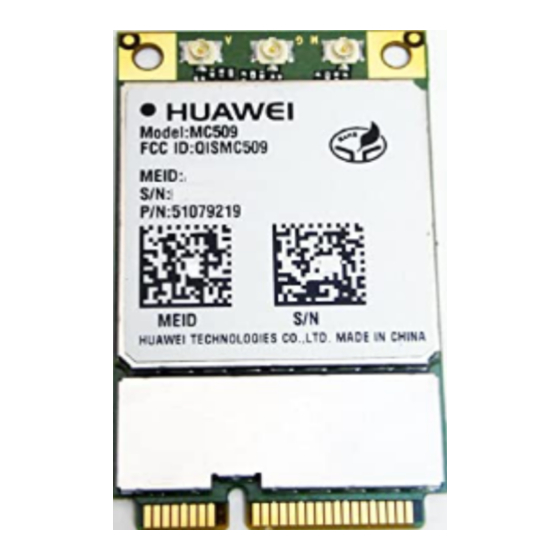
HUAWEI MC509 Series CDMA LGA Module Hardware Guide Mechanical Specifications Figure 6-3 Label for MC509 R=1mm MC509 QISMC509 28mm 1.1*1.1mm 28mm Figure 6-4 Label for MC509-a R=1mm A : 6.5mm A1 : 6.1mm B : 5.1mm B1: 4.7mm 28mm 1.1*1.1mm 28mm The picture mentioned above is only for reference. -
Page 65: Pcb Pad Design
HUAWEI MC509 Series CDMA LGA Module Hardware Guide Mechanical Specifications 6.8.2 PCB Pad Design To achieve assembly yields and solder joints of high reliability, it is recommended that the PCB pad size be designed as follows: Figure 6-5 Design of the solder pads on customers' PCBs (Unit: mm) 6.8.3 Solder Mask... -
Page 66: Assembly Processes
HUAWEI MC509 Series CDMA LGA Module Hardware Guide Mechanical Specifications When the PCB layout is double sided, it is recommended that the LGA module be placed on the second side for assembly; so as to avoid module dropped from PCB or component(located in module) re-melding defects caused by uneven weight. -
Page 67: Reflow Profile
Figure 6-6 Recommended stencil design of LGA module PCB PADS Stencil design Unit: mm The stencil design has been qualified for HUAWEI mainboard assembly, customers can adjust the parameters by their motherboard design and process situation to assure LGA soldering quality and no defect. 6.9.3 Reflow Profile For the soldering temperature of the LGA module, see the following figure. - Page 68 HUAWEI MC509 Series CDMA LGA Module Hardware Guide Mechanical Specifications Figure 6-7 Reflow profile Table 6-2 Reflow parameters Temperature Zone Time Key Parameter Preheat zone (40º C– 60s–120s Heating rate: 0.5º C/s–2º C/s 150º C) Soak zone (150º C– (t1–t2): 60s–120s Heating rate: <...
-
Page 69: Specification Of Rework
HUAWEI MC509 Series CDMA LGA Module Hardware Guide Mechanical Specifications 6.10 Specification of Rework 6.10.1 Process of Rework 6.10.2 Preparations of Rework Remove barrier or devices that can’t stand high temperature before rework. If the device to be reworked is beyond the storage period, bake the device according to Table 6-1 . -
Page 70: Welding Area Treatment
HUAWEI MC509 Series CDMA LGA Module Hardware Guide Mechanical Specifications Figure 6-8 Equipment used for rework 6.10.4 Welding Area Treatment Step 1 Remove the old solder by using a soldering iron and solder braid that can wet the solder. Step 2 Clean the pad and remove the flux residuals. -
Page 71: Specifications Of Rework
HUAWEI MC509 Series CDMA LGA Module Hardware Guide Mechanical Specifications 6.10.6 Specifications of Rework Temperature parameter of rework: for either the removing or welding of the module, the heating rate during the rework must be equal to or smaller than 3° C/s, and the peak temperature between 240º... -
Page 72: Certifications
This chapter gives a general description of certifications for MC509: Table 7-1 Product Certifications Certification Model name MC509 MC509-a RoHS The model of MC509-a module for CCC certification is HUAWEI MC509. Huawei Proprietary and Confidential Issue 02 (2013-05-06) Copyright © Huawei Technologies Co., Ltd. -
Page 73: Safety Information
HUAWEI MC509 Series CDMA LGA Module Hardware Guide Safety Information Safety Information Read the safety information carefully to ensure the correct and safe use of your wireless device. Applicable safety information must be observed. 8.1 Interference Power off your wireless device if using the device is prohibited. Do not use the wireless device when it causes danger or interference with electric devices. -
Page 74: Traffic Security
HUAWEI MC509 Series CDMA LGA Module Hardware Guide Safety Information Area indicated with the "Explosives" sign Area indicated with the "Power off bi-direction wireless equipment" sign Area where you are generally suggested to stop the engine of a vehicle 8.4 Traffic Security... -
Page 75: Care And Maintenance
Warning: Changes or modifications made to this equipment not expressly approved by HUAWEI may void the FCC authorization to operate this equipment Huawei Proprietary and Confidential Issue 02 (2013-05-06) -
Page 76: Appendix A Circuit Of Typical Interfaces
HUAWEI MC509 Series CDMA LGA Module Hardware Guide Appendix A Circuit of Typical Interfaces Appendix A Circuit of Typical Interfaces LGA Interface POWER SUPPLY U102 U101 HPA00615DRVR USB_5V 5V_P J101 C104 **1.8p MAIN_ANT MAIN_ANT EAR_OUT_N AUX_ANT USB_5V R105 AUX_ANT EAR_OUT_P... -
Page 77: Appendix B Acronyms And Abbreviations
HUAWEI MC509 Series CDMA LGA Module Hardware Guide Appendix B Acronyms and Abbreviations Appendix B Acronyms and Abbreviations Acronym or Abbreviation Expansion ACLR Adjacent Channel Leakage Power Radio AMPS Advanced Mobile Phone System Baseband CDMA Code-division Multiple Access European Conformity... - Page 78 HUAWEI MC509 Series CDMA LGA Module Hardware Guide Appendix B Acronyms and Abbreviations Acronym or Abbreviation Expansion Liquid Crystal Polyester Low-dropout Light-emitting Diode Low Noise Amplifier Low Pass Filter Multi-chip Package Noise Figure Negative Temperature Coefficient PBCCH Packet Broadcast Control Channel...