Table of Contents
Quick Links
Installation Manual
HIGH EFFICENCY
AIR HANDLER
Models:
• DR024GHFE18HT2
• DR036GHFE18HT2
• DR060GHFE18HT2
- R-410A REFRIGERANT
- 208/230V, 1 Phase, 60Hz
- 18 SEER
IMPORTANT NOTICE: Thank you very much for purchasing this Air Conditioner. Please read this manual carefully before
installing or operating your new air conditioning system. Be sure to save this manual for future reference.
CENTRAL SPLIT AIR CONDITIONER
Table of Contents

Related Manuals for Pioneer DR024GHFE18HT2


Summary of Contents for Pioneer DR024GHFE18HT2
- Page 1 CENTRAL SPLIT AIR CONDITIONER Installation Manual HIGH EFFICENCY AIR HANDLER Models: • DR024GHFE18HT2 • DR036GHFE18HT2 • DR060GHFE18HT2 - R-410A REFRIGERANT - 208/230V, 1 Phase, 60Hz - 18 SEER IMPORTANT NOTICE: Thank you very much for purchasing this Air Conditioner. Please read this manual carefully before...
- Page 2 This page intentionally left blank.
-
Page 3: Table Of Contents
Contents Safety Precautions............................1 Components of the Air Conditioner......................3 Troubleshooting .............................4 Filter Cleaning ..............................4 Installation and Maintenance....................5 1. Safety Notice ..............................5 2. Installation of the Indoor Unit ........................5 2.1. Initial Check ............................5 2.2. Installation Location..........................6 2.3. -
Page 4: Safety Precautions
Safety Precautions Alert Symbols: : This symbol refers to a hazard which can result in severe personal injury or death. DANGER : This symbol refers to a hazard or an unsafe practice which may result in severe personal injury WARNING or death. - Page 5 Safety Precautions WARNING PROPOSITION 65: This appliance contains fiberglass insulation. Respirable particles of fiberglass are known in the State of California to cause cancer. All manufacturer products meet current federal OSHA Guidelines for safety. California Proposition 65 warnings are required for certain products, which are not covered by the OSHA standards.
-
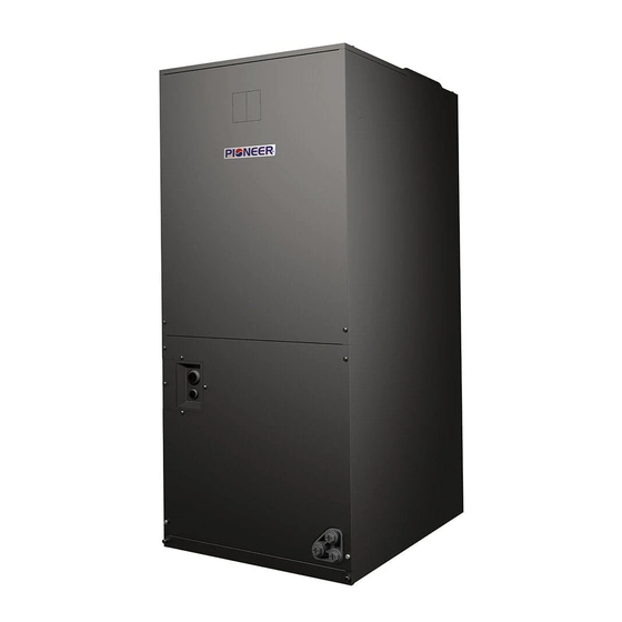
Page 6: Components Of The Air Conditioner
Components of the Air Conditioner Indoor Unit Air Outlet Flange Low Voltage Connection (for 24V) CircuitBreakerSwitch (Optional) Refrigerant Pipe (Liquid) Refrigerant Pipe (Gas) Air Inlet AuxiliaryDrainageHole DrainageHole AuxiliaryDrainage Hole High Voltage Connection High voltage connection Air Outlet Electric Box Auxiliary Heater (Optional) Fan Volute Evaporator Drainage Pan... -
Page 7: Troubleshooting
Troubleshooting Troubleshooting CAUTION If drainage water overflows from the indoor unit, cease all operation and contact your dealer. If you smell or see white smoke coming out of the unit, turn OFF the main power supply and contact your dealer. 1. -
Page 8: Installation And Maintenance
Installation and Maintenance 1. Safety Notice and Tips WARNING • Install the air conditioner on a solid base that can support the unit's weight. (An inadequate base or incomplete installation may cause injury, due to falling off from the base.) •... -
Page 9: Installation Location
Installation and Maintenance 2.2 Installation Location Before selecting the installation site, obtain all required permissions and follow the below parameters: ·Optimal air distribution is ensured. ·The air path is not blocked or obstructed. ·Condensation is able to drain properly. ·Ensure sufficient clearance for future maintenance and servicing. -
Page 10: Refrigerant Pipe
Installation and Maintenance Sheet metal ductwork run in unconditioned spaces Nitrogen should flow through the refrigerant lines must be insulated and covered with a vapor barrier. while brazing. Fibrous ductwork may be used if constructed and Use a wet rag or an approved heat paste to protect installed in accordance with SMACNA Construction the TXV sensing bulb during the brazing process. -
Page 11: Electrical Wiring
Installation and Maintenance 6. Electrical Wiring 6.1. Electrical Installation CAUTION · Before proceeding with electrical connections, ensure that power supply is as specified on the unit rating plate. See unit wiring label for proper field high and low-voltage wiring. Make all electrical connections in accordance with the NEC and any local codes or ordinances that may apply. -
Page 12: Change Of Static Pressure
Installation and Maintenance 6.2 Change of Static Pressure The static pressure can be selected by changing the Dip Switches on the electrical board. Static Pressure Setting: Dip Switch S2 Static Pressure Static Pressure Static Pressure Blower Speed Tap Fan Speed Select Setting (W.C.[kPa]) 24K (W.C.[kPa]) 36K... -
Page 13: Txv Replacement Information
Installation and Maintenance Installation and Maintenance 8.TXV Replacement Information Please follow the steps below when replacing the TXV: Disassemble the front panel. Take the thermal bulb down by undoing the copper strips around it. Weld the pressure pipe off from the gas pipe with a welding gun. Be careful not to burn the gas pipe. Weld the TXV off from the liquid pipe with a welding gun. - Page 14 This page intentionally left blank.
- Page 15 This page intentionally left blank.
- Page 16 3250 NW 107 Avenue, Doral, FL 33172 - USA : (305) 513-4488 : (305) 513-4499 E-mail : [email protected] Website : www.pd-hvac.com Pioneer product line, parts, and supplies are available online for convenient ordering at: www.highseer.com www.pioneerminisplit.com Scan the below code to visit our support page where you can find more installation materials: Copyright 2020, Parker Davis HVAC International, Inc., All rights reserved.