Table of Contents
READ AND SAVE THESE INSTRUCTIONS
Thank you for purchasing this Panasonic product.
Please read these instructions carefully before attempting to install, operate or service
the Panasonic product. Please carefully read the "IMPORTANT INSTRUCTIONS".
Failure to comply with instructions could result in personal injury or property damage.
Please explain to users how to operate and maintain the product after installation,
and this booklet should be presented to users.
Please retain this booklet for future reference.
OPERATING AND INSTALLATION
Contents
FV-0511VH1
PRODUCT SERVICE
FV-0511VHL1
INSTRUCTIONS
FV-0511VH1
Model No.
FV-0511VHL1
------------------------------------5
--------------------------------------6
-----------------------6
-------------------------------------6~7
-------------------------------------7
--------------------12
-------------------------------------13
-----------------------------14~15
--------------------BACK COVER
-----------------BACK COVER
Fan Heater
-----------------2~4
------------8
----8~11
--BACK COVER
Table of Contents

Related Manuals for Panasonic FV-0511VH1


Summary of Contents for Panasonic FV-0511VH1
-
Page 1: Table Of Contents
Thank you for purchasing this Panasonic product. Please read these instructions carefully before attempting to install, operate or service the Panasonic product. Please carefully read the “IMPORTANT INSTRUCTIONS”. Failure to comply with instructions could result in personal injury or property damage. -
Page 2: Important Instructions
IMPORTANT INSTRUCTIONS Read all instructions before installing or using this fan heater. For Your Safety To reduce the risk of injury, loss of life, electric shock, fire, malfunction, and damage to equipment or property, always observe the following safety precautions. Explanation of symbol word panels The following symbol word panels are used to classify and describe the level of hazard, injury, and property damage caused when the denotation is disregarded and improper... - Page 3 IMPORTANT INSTRUCTIONS CONTINUED Follow all local electrical and safety codes, as well as the National Electrical Code (NEC) and the Occupational safety and Health Act. Use only on 20 ampere branch circuit. This fan heater must be properly grounded. Ceiling joist must be able to withstand a static load more than five times the weight of the fan heater.
- Page 4 IMPORTANT INSTRUCTIONS CONTINUED Do not insert or allow foreign objects to enter any ventilation or exhaust opening as this may cause an electric shock or fire, or damage the fan heater. This fan heater is hot when in use. To avoid burns, do not let bare skin touch the hot surfaces of the fan heater.
-
Page 5: Description
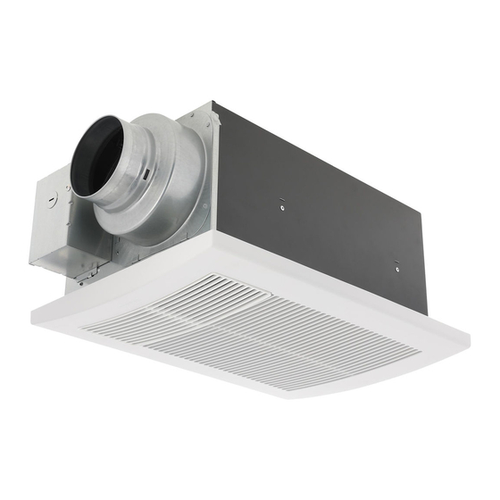
DESCRIPTION The Panasonic fan heater uses a sirocco fan driven by a DC motor powered by an integral transformer. The motor is designed to have long operating life, high dynamic response, higher speed ranges and energy efficiency. The grille covering the fan heater body is attached with the mounting springs for quick removal. -
Page 6: Unpacking
FOR MODEL FV-0511VH1 Flex-Z Fast™ Heat Vent bracket Light Night-Light (with 4 tapping FOR MODEL FV-0511VHL1 Switch label screws POUR LE MODÈLE FV-0511VH1 -ST4.2X20) Chaleur Ventilation Lumière Self-drilling Veilleuse screw POUR LE MODÈLE FV-0511VHL1 FEATURES Heater Performance: This fan heater, WhisperWarm uses a PTC (Positive Temperature Coefficient) heater. This is a quick and efficient means to warm up a bathroom. -
Page 7: Dimensions
Unit: inches (mm) 3 7/8 (100) 16 (407) 1 1/2 (37) 4 1/2 (114) 7 1/2 (190) 18 1/4 (464) 18 1/4 (464) FV-0511VH1 FV-0511VHL1 Part name Part name Fan body Lighting unit Grille Flex-Z Fast™ bracket Adaptor PCB box Blade Pick-A-Flow™... -
Page 8: Installation (Wiring Diagram)
INSTALLATION ( WIRING DIAGRAM ) FV-0511VH1 FV-0511VHL1 NIGHT LIGHT BLUE VENTILATION WHITE AC120 V LIGHT BLACK 60 Hz BLACK AC120 V HEAT 60 Hz VENTILATION WHITE GREEN BLACK AC120 V HEAT 60 Hz WHITE WHITE GREEN STEPPER WHITE TAB2 TAB1... - Page 9 INSTALLATION ( NEW CONSTRUCTION ) CONTINUED STEP 2 Bend down 4 tabs Bend down 4 tabs for positioning, install the Flex-Z Fast™ bracket to joists by drilling 2 Joist tapping screws (pre-fixed on the Flex-Z Fast™ bracket). (Fig.2) Flex-Z Fast™ bracket 2 Tapping screws (ST4.2X20) Fig.2...
- Page 10 INSTALLATION ( NEW CONSTRUCTION ) CONTINUED STEP 7 WARNING For Live (Heat) and Neutral (Common for Use only on 20 ampere branch circuit. Heat and Vent), AWG 14 or more must be used when wiring. This fan heater must be properly grounded. CAUTION When making wiring connections take Wiring procedures and connections shall...
- Page 11 INSTALLATION ( NEW CONSTRUCTION ) CONTINUED STEP 10 (Perform as needed) Tapping screw Grille blades Remove the grille blade holder to adjust ( 4X12) orientation of the grille blades to adjust the Grille direction of warm air flow. (Fig. 8) IMPORTANT: Align the arrow marks on the grille blades with the desired air direction.
-
Page 12: Installation (Retrofit)
INSTALLATION ( RETROFIT ) STEP 1 Unit: inches (mm) WARNING Joist Installation work and electrical wiring must Ceiling drywall be done by qualified person(s) in accordance (already existed) with all applicable codes and standards, Fig.12 including fire-rated construction. Neither unauthorized modification, repair nor disassembly is allowed. -
Page 13: Operation
Vent while keeping the Ventilating bathroom warm For Model For Model “Vent” FV-0511VHL1 FV-0511VH1 “Light” Light Turns on the main light Fig.16 Attach switch labels to the wall “Night-Light” Night-Light Turns on the night light switch as shown above. (Fig.16) Switching operating modes requires a slight delay to change the internal shutter positions. -
Page 14: Maintenance
Remove only this side. The filter must be maintained every three months. Slot Squeeze the mounting spring and pull down carefully Gloves and remove specified side of the grille. (Fig.17) Panasonic logo Warm air Fig.17 outlet Fig.10 STEP 2 Filter Remove the filter. - Page 15 Mounting spring Squeeze the mounting spring and pull down carefully Remove only this and remove specified side of the grille. (Fig.22) side. Slot Panasonic Warm air logo outlet Fig.22 Fig.10 STEP 4 Remove dust and dirt from the fan body using a vacuum cleaner.
-
Page 16: Practical Guide To Installation
The unit should be serviced by qualified technicians only. Your product is designed and manufactured to ensure a minimum of maintenance. Should your unit require service or parts, call Panasonic Call Center at 1-800-669-5165. Panasonic Canada Inc. 5770 Ambler Drive, Mississauga, Ontario L4W 2T3 www.panasonic.com...