
Related Manuals for Siemens Cerberus PACE Compact


Summary of Contents for Siemens Cerberus PACE Compact
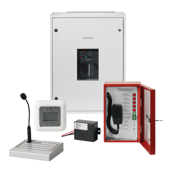
- Page 1 Cerberus PACE Compact Public Address and Controlled Evacuation Installation Mounting A6V11899867_en--_a Smart Infrastructure 2020-12-30...
- Page 2 All rights created by patent grant or registration of a utility model or design patent are reserved. Issued by: Siemens Switzerland Ltd. Smart Infrastructure Global Headquarters Theilerstrasse 1a CH-6300 Zug Tel. +41 58 724-2424 www.siemens.com/buildingtechnologies Edition: 2020-12-30 Document ID: A6V11899867_en--_a © Siemens Switzerland Ltd, 2020 2 | 122 A6V11899867_en--_a...
-
Page 3: Table Of Contents
Table of contents About this document .................. 13 Applicable documents ................... 16 Download center ................... 16 Revision history ..................... 17 Safety ......................18 Safety notes ....................18 Safety regulations for the method of operation ..........19 Responsibility of the operator ................ 21 Standards and directives complied with ............ - Page 4 4.23 Install system fault relay output ..............57 4.24 Install fans ..................... 58 Power supply and batteries ............... 59 Power supply in PC1001 ................59 5.1.1 Installation ..................59 5.1.2 Connect mains power ..............60 5.1.3 Connect DC 24 V power output ............. 60 5.1.4 Connect batteries ................
- Page 5 6.5.5 Connect 'PACE-Bus' (RS485) ............84 6.5.6 Logic control inputs ................ 84 6.5.7 Analog control inputs ..............85 6.5.8 Relay outputs ................. 86 Output module (relay, 8) PCO2002-A1 ............87 6.6.1 Mounting ..................87 6.6.2 Installation ..................87 6.6.3 Configuration with the ID-Switch............ 87 6.6.4 Connect DC 24 V power supply.............
- Page 6 7.4.10 PACE-Bus RS232 serial interface ..........108 7.4.11 Mount the SD card ............... 108 Call station PT2009-A1 ................109 7.5.1 Mounting ..................109 7.5.2 Installation ..................109 7.5.3 Connect to a cabinet ..............110 7.5.4 Install one PT2009-A1 ..............113 7.5.5 Analog audio inputs ..............
- Page 7 List of figures Fig. 1: PC1001-A3 position of the screws ............... 25 Fig. 2: PC1001-A3 installation overview..............28 Fig. 3: PC1002-A3 installation overview..............29 Fig. 4: PC1001-A3 mains connector with pre-assembled wiring ......31 Fig. 5: PC1002-A3 mains connector 'X100' with pre-assembled wiring ....32 Fig.
- Page 8 Fig. 34: PC1001-A3 power supply connectors ............59 Fig. 35: Wiring diagram for 1x battery sets ............. 62 Fig. 36: Wiring diagram for the batteries in the PP2004-A1 ........64 Fig. 37: PT1001-A1 unmount front door blind plate ..........66 Fig.
- Page 9 List of tables Table 1: PC1001-A3 mains connector - 'X100' ............31 Table 2: PC1002-A3 mains connector - 'X100' ............32 Table 3: PC1002-A3 mains connector - 'X102' ............33 Table 4: PC100x-A3 power supply connector - 'PS-24V' ........34 Table 5: PC100x-A3 power supply connector - 'PS-Fault' ........
- Page 10 Table 34: PT1001-A1 set RS485 address with ID switches ........67 Table 35: PT1001-A1 DC 24 V power supply connector - 'X1' ......68 Table 36: PT1001-A1 'PACE-Bus' (RS485) connector - 'X2' ......... 68 Table 37: PT1001-A1 logic control outputs connector - 'X3' ........68 Table 38: PT1001-A1 logic control inputs connector - 'X4' ........
- Page 11 Table 71: PT2001-A1 analog audio input 1 and 2 connector - 'CN1' ...... 93 Table 72: PT2001-A1 analog audio output 1 and 2 connector - 'CN5' ....93 Table 73: PT2001-A1 logic control inputs connector - 'CN7'........93 Table 74: PT2001-A1 logic outputs connector - 'CN3' ..........94 Table 75: PT2001-A1 analog control inputs connector - 'CN1' .......
-
Page 13: About This Document
Connecting the pre-installed devices to the building infrastructure. ● Connecting batteries and the power supply. Scope The information contained in this document is valid for Cerberus PACE Compact. Target groups The information in this document is intended for the following target groups: A6V11899867_en--_a... - Page 14 About this document Applicable documents Target group Activity Qualification ● ● System owner According to EN 50110-1, 'This person can be the owner, 'nominated person with the overall employer, proprietor or a delegated responsibility to ensure the safe person.' operation of the electrical ●...
- Page 15 About this document Applicable documents Date format The date format in the document corresponds to the recommendation of international standard ISO 8601 (format YYYY-MM-DD). Presentation conventions Text markups Special text markups are used as follows in this document: ⊳ Prerequisite for an instruction telling you what to do Instruction with at least two steps ◈...
-
Page 16: Applicable Documents
About this document Applicable documents 1.1 Applicable documents You will find more information on the Cerberus PACE Compact system and its components in the following documents: Title Document ID IT security policies Cerberus PACE Compact – IT security policies A6V11439692 System documentation Cerberus PACE Compact –... -
Page 17: Revision History
About this document Revision history 1.3 Revision history The reference document's version applies to all languages into which the reference document is translated. The first edition of a language version or a country variant may, for example, be version 'd' instead of 'a' if the reference document is already this version. The table below shows this document's revision history: Version Edition date... -
Page 18: Safety
Safety Safety notes 2 Safety 2.1 Safety notes Comply with the following safety notes to protect life, limb, and property. The safety notes in the document include the following elements: ● Symbol for hazard ● Signal word ● Type and source of hazard ●... -
Page 19: Safety Regulations For The Method Of Operation
2.2 Safety regulations for the method of operation National standards, regulations and legislation Siemens products are developed and produced in compliance with the relevant European and international safety standards. Should additional national or local safety standards or legislation concerning the planning, mounting, installation,... - Page 20 Siemens and the corresponding safety bodies for modifications or additions. Modules and spare parts ● Components and spare parts must comply with the technical specifications defined by Siemens. Only use products specified or recommended by Siemens. ● Only use fuses with the specified fuse characteristics. ●...
-
Page 21: Responsibility Of The Operator
– for example, in rooms with a high concentration of dust, high levels of air humidity, or significant temperature fluctuations. 2.4 Standards and directives complied with A list of the standards and directives complied with is available from your Siemens contact. A6V11899867_en--_a 21 | 122... -
Page 22: Cyber Security Disclaimer
Siemens’ portfolio undergoes continuous development to make it more secure. Siemens strongly recommends that updates are applied as soon as they are available and that the latest versions are used. Use of versions that are no longer supported, and failure to apply the latest updates may increase your exposure to cyber threats. -
Page 23: Preparatory Work
Preparatory work Installation site 3 Preparatory work This chapter contains all the instructions that must be carried out or ensured by the customer before the system is mounted and installed. 3.1 Installation site General guidelines ● The housings used must conform to the types listed in the documentation and have to meet at least protection category IP 30, in accordance with EN 60529:1991 or EN 60529:1991/A2:2000. -
Page 24: Electrical Supply Lines
Preparatory work Electrical supply lines 3.3 Electrical supply lines General guidelines 1. Read the safety instructions for electrical installations in Safety regulations for the method of operation. 2. Batteries must only be inserted and connected in the housing by authorized specialist personnel. -
Page 25: Mounting/Installation
Mounting/Installation Mount the cabinet 4 Mounting/Installation 4.1 Mount the cabinet The 'Voice alarm panel Compact 400' PC1001-A3 and the 'Voice alarm panel Compact 1000' PC1002-A3 cabinets are mounted on the wall with 4 screws. A position for the cabinet should be defined. All peripheral cable entrances are on the top of the cabinet. -
Page 26: Change The Cabinet Door Hinge
Mounting/Installation Change the cabinet door hinge 4.2 Change the cabinet door hinge The door hinge of the 'Voice alarm panel Compact 400' PC1001-A3 and the 'Voice alarm panel Compact 1000' PC1002-A3 cabinets can be changed with the following steps: 1. Unscrew the two door locks and remove both screws from them. 2. - Page 27 Mounting/Installation Change the cabinet door hinge 7. Remove the upper and lower door holders. – A: take off the washer – B: unscrew the hinge stud 8. Take the spring out of the hinge. 9. Mount the door holders on the other side of the door: –...
-
Page 28: Installation Overview Pc1001
Mounting/Installation Installation overview PC1001 4.3 Installation overview PC1001 The figure below is an installation overview of the 'Voice alarm panel Compact 400' PC1001-A3 cabinet. It displays the mounting options and the installation areas in the cabinet. The power supply, the fan connectors and the speaker line connectors are pre- assembled. -
Page 29: Installation Overview Pc1002
Mounting/Installation Installation overview PC1002 4.4 Installation overview PC1002 The figure below is an installation overview of the 'Voice alarm panel Compact 1000' PC1002-A3 cabinet. It displays the mounting options and installation areas in the cabinet. The power supply, the mains filter, the fan connectors and the speaker line connectors are pre-assembled. -
Page 30: Wire The Mains Supply Line
Mounting/Installation Wire the mains supply line 4.5 Wire the mains supply line WARNING Electrical voltage Electric shock ● Work on electrical installations may only be carried out by qualified electricians or by instructed persons working under the guidance and supervision of a qualified electrician, in accordance with the electrotechnical regulations. -
Page 31: Mains Connection Pc1001
Mounting/Installation Wire the mains supply line 4.5.1 Mains connection PC1001 The 230 V mains connector of the 'Voice alarm panel Compact 400' PC1001-A3 is in the upper right of the cabinet. The power supply and the PE in the cabinet are already pre-assembled. -
Page 32: Mains Connection Pc1002
Mounting/Installation Wire the mains supply line 4.5.2 Mains connection PC1002 The 230 V mains connection of the 'Voice alarm panel Compact 1000' PC1002-A3 is divided into 2 connectors: the mains connector 'X100' and the mains connector 'X102'. The 'X100' is used to connect the mains connection and connect the mains filter. -
Page 33: Fig. 6: Pc1002-A3 Mains Connector 'X102' With Pre-Assembled Wiring
Mounting/Installation Wire the mains supply line 4.5.2.2 Mains connector 'X102' on PC1002 Fig. 6: PC1002-A3 mains connector 'X102' with pre-assembled wiring Connection to the power supply; pre-assembled X102 Terminal block for the internal mains supply connection Mains connector - 'X102' Designator Connection Color Description... -
Page 34: Connection To The Power Supply
Mounting/Installation 24 V connection to the power supply 4.6 24 V connection to the power supply The 24 V is required on the digital audio matrix board with DC 24 V power. It is connected to the power supply via the 'PS-24V' connector. An earth connection to the cabinet is required for a proper work of the digital audio matrix board. -
Page 35: Mount And Install Additional Power Amplifiers
Mounting/Installation Mount and install additional power amplifiers 4.7 Mount and install additional power amplifiers 4.7.1 Mount and install additional power amplifiers on PC1001 Only the 'Power amplifier (1x200W)' PV1001-A1 can be mounted in the 'Voice alarm panel Compact 400' PC1001-A3 cabinet. Other amplifier types are not allowed. -
Page 36: Mount And Install Additional Power Amplifiers On Pc1002
Mounting/Installation Mount and install additional power amplifiers 4.7.2 Mount and install additional power amplifiers on PC1002 Only the 'Power amplifier (1x500W)' PV1002-A1 can be mounted in the 'Voice alarm panel Compact 1000' PC1002-A3 cabinet. Other amplifier types are not allowed. The power amplifiers PV1002-A1 are mounted in the amplifier mounting area. -
Page 37: Fig. 10: Pc1002-A3 Power Amplifiers Mounting Positions
Mounting/Installation Mount and install additional power amplifiers Fig. 10: PC1002-A3 power amplifiers mounting positions The amplifier on position 'Amp 5' is used as the pilot tone amplifier. The amplifier on position 'Amp 6' is used as a backup amplifier. These two amplifiers can’t be used as regular amplifiers with speaker lines connected. -
Page 38: Fig. 12: Pc1002-A3 Power Amplifiers Connectors
Mounting/Installation Mount and install additional power amplifiers 230 V connector Description Remark AC 230 V N Blue No connection AC 230 V L1 Brown Table 9: PV1002-A1 230 V connector Fig. 12: PC1002-A3 power amplifiers connectors PC1002-A3 amplifier connectors - 'TR1' to 'TR6' Description Remark Do not use... -
Page 39: Configure Speaker Lines
The fault and clip LEDs are active when the amplifier is in OFF mode. 4.8 Configure speaker lines The Cerberus PACE Compact speaker line configuration is performed via the speaker lines jumper configuration matrix. The speaker lines can’t be configured via the configuration tool 'PACE-Design', but the speaker line jumper settings can be checked in the 'PACE-Design'. -
Page 40: Fig. 14: Pc100X-A3 Jumper Key
Mounting/Installation Configure speaker lines The jumper settings are changed with the jumper key. Insert the jumper key to a jumper, pull the jumper out and place it on the new position. Fig. 14: PC100x-A3 jumper key The 16 speaker line zones can be configured to the 4 amplifiers. The speaker line configuration matrix has 16 columns representing the 16 speaker line zones and 4 rows representing the 4 amplifiers. -
Page 41: Install Speaker Lines
Mounting/Installation Install speaker lines 4.9 Install speaker lines The speaker lines are connected to the speaker line output connectors X101-1 and X101-2. The speaker lines can be configured in stub or in loop configuration. In stub configuration the speaker lines can be supervised with PCA2004-A1 EOL3 (active) or with impedance supervision. -
Page 42: Table 12: Speaker Line Connector - 'X101-1
Mounting/Installation Install speaker lines Descriptio Stub configuration Loop configuration Line 7+ Loop 4 Start + Line 7- Loop 4 Start - Line 8+ Loop 4 End + Line 8- Loop 4 End - Table 12: Speaker line connector - 'X101-1' Speaker line connector - 'X101-2' Descriptio Stub configuration... -
Page 43: Pace-Net Ethernet
The Cerberus PACE Compact audio matrix board provides 2 'PACE-Net' copper Ethernet cables (CAT5) with RJ45 connectors (A and B) in the options area. These connectors can be used to connect further Cerberus PACE Compact or Cerberus PACE modular systems, 'PACE-Net' call stations or a PC with the configuration tool 'PACE-Design' installed. -
Page 44: Mount And Install Pn1001-A1
Switch' PN2005-A1 is used to create a ring structure. 4.12 Install the micro SD card The Cerberus PACE Compact systems PC1001-A3 and PC1002-A3 are equipped with a micro SD card slot in the options area. The micro SD card is pre-installed. To change the micro SD card, pull it out from the micro SD card slot and insert a new one in the correct direction. -
Page 45: Pace-Bus Rs485
Mounting/Installation PACE-Bus RS485 4.13 PACE-Bus RS485 Both PC1001-A3 and PC1002-A3 Cerberus PACE Compact audio matrix boards provide 4 'PACE-Bus' (RS485) connectors ('1-RS485' to '4-RS485') in the options area. These connectors can be used to connect the 'PACE-Bus' (RS485) operating terminals and the 'PACE-Bus' (RS485) call stations. -
Page 46: Mount And Install Pn1002-A1
24 V with integrated ground fault detection, and connectors for isolated analog audio inputs and outputs. One PN1002-A1 can be mounted on the Cerberus PACE Compact audio matrix board in the options area. Mount the PN1002-A1 on position 'UI1' on the digital audio matrix board. Plug the PN1002-A1 to the connectors 'UI1-A' and 'UI1-B'. -
Page 47: Table 17: Pn1002-A1 Single Wire Connector - 'Cn1
Mounting/Installation Mount and install PN1002-A1 Single wire connector - 'CN1' Description Remark Signal out + Analog audio out + Signal out - Analog audio out - 24 V Isolated 24 V Isolated RS485 data - Isolated RS485 data + GND of isolated 24 V Signal in + Analog audio in + Signal in -... -
Page 48: Install Pace-Bus Rs232
Table 18: PN1002-A1 RJ45 connector - 'J4' 4.15 Install PACE-Bus RS232 The PC1001-A3 and PC1002-A3 Cerberus PACE Compact digital audio matrix boards both provide one 'PACE-Bus' (RS232) connector (RS232) in the options area. This connector can be used for connecting the 'PACE-Bus' (RS232) option modules and for diagnosis. -
Page 49: Install 24 V
Install 24 V 4.16 Install 24 V The PC1001-A3 and PC1002-A3 Cerberus PACE Compact digital audio matrix boards both provide 4x 24 V connectors ('1-24V' to '4-24V') in the options area. These connectors can be used to connect the 24 V to option modules. -
Page 50: Install Analog Audio Inputs
Mounting/Installation Install analog audio inputs 4.17 Install analog audio inputs The PC1001-A3 and PC1002-A3 Cerberus PACE Compact digital audio matrix boards both provide 4 connectors ('1-AI' to '4-AI') with 4 balanced analog audio inputs in the audio area. The analog audio inputs are used to connect analog audio devices like microphones or audio media players to the digital audio matrix board. -
Page 51: Install Analog Audio Outputs
Mounting/Installation Install analog audio outputs 4.18 Install analog audio outputs The PC1001-A3 and PC1002-A3 Cerberus PACE Compact digital audio matrix boards both provide 4 connectors ('1-AO' to '4-AO') with 4 analog audio outputs in the audio area. The analog audio outputs are used to connect analog audio devices like speakers or audio amplifiers to the digital audio matrix board. -
Page 52: Install Microphone Switches
Install microphone switches 4.19 Install microphone switches The PC1001-A3 and PC1002-A3 Cerberus PACE Compact digital audio matrix boards both provide 1 connector ('Mic-S') with 2 switch inputs in the audio area. The microphone switch connector is used to connect the switch of the... -
Page 53: Install Logic Control Inputs
Mounting/Installation Install logic control inputs 4.20 Install logic control inputs The PC1001-A3 and PC1002-A3 Cerberus PACE Compact digital audio matrix boards both provide 1 connector ('DI') with 8 logic control inputs in the input/output area. The logic control inputs are used to get information and controls from the connected devices. -
Page 54: Use Logic Control Inputs
Mounting/Installation Install logic control inputs 4.20.1 Use logic control inputs Fig. 28: Use of logic control inputs An electrically isolated switch is required for this function. The switch is connected between the 10 V and a logic control input. 54 | 122 A6V11899867_en--_a... -
Page 55: Install Analog Control Inputs
Mounting/Installation Install analog control inputs 4.21 Install analog control inputs The PC1001-A3 and PC1002-A3 Cerberus PACE Compact digital audio matrix boards both provide 1 connector ('AI') with 8 analog control inputs in the input/output area. The analog control inputs are used as a local gain control or as a control for audio output volume. -
Page 56: Use Analog Control Inputs
The resistor is connected between GND and 10 V. The wiper is connected to an analog control input. 4.22 Install relay outputs The PC1001-A3 and PC1002-A3 Cerberus PACE Compact digital audio matrix boards both provide 8 connectors ('1-DO' to '8-DO') with 8 relay outputs in the logic out area. -
Page 57: Install System Fault Relay Output
Install system fault relay output 4.23 Install system fault relay output The PC1001-A3 and PC1002-A3 Cerberus PACE Compact digital audio matrix boards both provide a dedicated potential free system fault relay connector. This connector lies in the inputs/outputs area on the lower left side of the board. -
Page 58: Install Fans
Install fans 4.24 Install fans 2 fans are pre-installed in the Cerberus PACE Compact cabinets in the upper right and left sides. The fans are not active in the regular working mode. The fans are activated in the case when: ●... -
Page 59: Power Supply And Batteries
Power supply and batteries Power supply in PC1001 5 Power supply and batteries Only one battery block can be installed in the PC1001-A3 or PC1002-A3 wall mount cabinet. It is buffered via the power supply. General guidelines Do not connect the batteries after installation; instead, connect them immediately before commissioning starts. -
Page 60: Connect Mains Power
Power supply and batteries Power supply in PC1001 5.1.2 Connect mains power The PC1001-A3 power supply provides an AC 230 V screw terminals ('Mains') Mains power AC 230 V connector - 'Mains' Designator Connection Color PE, earth Protective conductor Yellow/green Neutral conductor Blue Outer conductor... -
Page 61: Connect Fault Relays
Power supply and batteries Power supply in PC1001 5.1.5 Connect fault relays The PC1001-A3 power supply provides two connectors ('MF' and 'GF') to connect the power supply fault relays. Mains fault relay connector - 'MF' Designator Connection Color MF-NO Connected to C if fault Blue occurs (normally open) MF-C... -
Page 62: Power Supply In Pc1002
Power supply and batteries Power supply in PC1002 5.2 Power supply in PC1002 The power supply of the 'Voice alarm panel Compact 1000' PC1002-A3 is mounted and pre-assembled in the cabinet with the following connections: ● 230 V IEC plug connection ●... - Page 63 Power supply and batteries Power supply in PC1002 Power unit terminal Connection Conductor color Bat 24 V 1/+ Battery +24 V Battery – 0 V Bat 24 V 1/- Blue Bat 1/M Equalizing charge connection for Black battery block 1 Bat 2/M Equalizing charge connection for Black...
-
Page 64: External Power Supply Pp2004
Power supply and batteries External power supply PP2004 5.3 External power supply PP2004 The external power supply 'Merawex ZSP135 DR-7A-3 40 Ah' PP2004-A1 is a wall-mounted power supply with batteries and the following connections: ● 230 V mains connection via power supply terminals ●... - Page 65 Power supply and batteries External power supply PP2004 ● The temperature sensor must be positioned directly next to the batteries. ● The battery separator must be mounted as close as possible to the battery's positive terminal. A6V11899867_en--_a 65 | 122...
-
Page 66: Install Internal Components
Cerberus PACE Compact cabinet in place of the mounted blind plate. Fig. 37: PT1001-A1 unmount front door blind plate 1. Take off the earth connection at the blind plate of the Cerberus PACE Compact cabinet font door. 2. Unscrew the 8 screws of the blind plate. -
Page 67: Configuration With The Id-Switch
Install internal components System operating unit PT1001-A1 6.1.2 Configuration with the ID-Switch The ID-Switch must be set to the correct values to identify the components on the 'PACE-Bus' (RS485). The ID must be unique on one 'PACE-Bus' (RS485). Description Not allowed Not allowed Table 34: PT1001-A1 set RS485 address with ID switches ●... -
Page 68: Connect Dc 24 V Power Supply
Install internal components System operating unit PT1001-A1 6.1.4 Connect DC 24 V power supply The PT1001-A1 provides one DC 24 V power supply connector ('X1'). DC 24 V power supply connector - 'X1' Description Remark DC 24 V DC 0 V Table 35: PT1001-A1 DC 24 V power supply connector - 'X1' 6.1.5 Connect 'PACE-Bus' (RS485) The PT1001-A1 provides one 'PACE-Bus' (RS485) connector ('X2'). -
Page 69: Logic Control Inputs
Install internal components System operating unit PT1001-A1 6.1.7 Logic control inputs The PT1001-A1 provides 4 logic control inputs on the connector 'X4'. The logic control inputs are used to get information and controls from the connected components. ● Logic 0 with input voltage <3 V ●... -
Page 70: Operating Unit And Call Stations Pt1002-A1
6.2.1 Mounting The 'System operating unit and call station' PT1002-A1 is designed to be mounted on a front door of a Cerberus PACE Compact cabinet in place of the mounted blind plate. Fig. 39: PT1002-A1 unmount front door blind plate 1. -
Page 71: Configuration With The Id-Switch
Install internal components Operating unit and call stations PT1002-A1 6.2.2 Configuration with the ID-Switch The ID-Switch must be set to the correct values to identify the components on the 'PACE-Bus' (RS485). The ID must be unique on one 'PACE-Bus' (RS485). Description Not allowed Not allowed... -
Page 72: Installation
Install internal components Operating unit and call stations PT1002-A1 6.2.3 Installation The PT1002-A1 is pre-assembled with an adapter board. Connect the copper Ethernet cable (CAT5) from the PTO2008-A1 (see 6.3 [➙ 73] ) to the PT1002-A1 adapter board. Make sure that the cable is fixed on the front door and in the cabinet with pull reliefs. -
Page 73: Call Station Interface (Rs485) Pto2008-A1
Install internal components Call station interface (RS485) PTO2008-A1 6.3 Call station interface (RS485) PTO2008-A1 The 'PACE-Bus' module 'Call station interface (RS485)' PTO2008-A1 provides a convenient connection to the call stations PT1002-A1, PT2003-A1 and PT2009-A1. It routes all signals to a copper Ethernet cable (CAT5) to connect the call stations and further PTO2008-A1. -
Page 74: Connect 'Pace-Bus' (Rs485)
Install internal components Call station interface (RS485) PTO2008-A1 6.3.4 Connect 'PACE-Bus' (RS485) The PTO2008-A1 provides one 'PACE-Bus' (RS485) connector ('X2'). 'PACE-Bus' (RS485) connector - 'X2' Description Remark RS485 data - RS485 data + GND reference voltage Not used Table 41: PTO2008-A1 'PACE-Bus' (RS485) connector - 'X2' 6.3.5 Connect analog audio inputs The PTO2008-A1 provides one connector ('X3') for analog audio inputs connected to the call station microphone. -
Page 75: Connect To Call Station
Install internal components Call station interface (RS485) PTO2008-A1 6.3.7 Connect to call station The PTO2008-A1 provides two connectors ('X5' and 'RJ1') to connect the call stations. 'RJ1' uses a copper Ethernet cable (CAT5) for the connection. Call station connectors - 'X5' and 'RJ1' Description Remark Audio-Out +... -
Page 76: Input/Output Extension (Digital 16) Pcio2001-A1
Install internal components Input/Output extension (digital 16) PCIO2001-A1 6.4 Input/Output extension (digital 16) PCIO2001-A1 The 'PACE-Bus' module 'Input/Output extension (digital 16)' PCIO2001-A1 provides: ● 16 logic control outputs with open collector ● 16 logic control inputs ● 8 analog control inputs 6.4.1 Mounting The 'PACE-Bus' module 'Input/Output extension (digital 16)' PCIO2001-A1 is designed to be mounted on a DIN rail in the cabinet. -
Page 77: Configuration With The Id-Switch
Install internal components Input/Output extension (digital 16) PCIO2001-A1 6.4.3 Configuration with the ID-Switch The ID-Switch must be set to the correct values to identify the components on the 'PACE-Bus' (RS485). The ID must be unique on one 'PACE-Bus' (RS485). The ID switch 7 and 8 are used to set the RS485 address. Table 46: PCIO2001-A1 set the RS485 address with ID switches ●... -
Page 78: Connect 'Pace-Bus' (Rs485)
Install internal components Input/Output extension (digital 16) PCIO2001-A1 6.4.5 Connect 'PACE-Bus' (RS485) The PCIO2001-A1 provides one 'PACE-Bus' (RS485, RS232) connector ('X5'). 'PACE-Bus' (RS485) connector - 'X5' Description Remark 10 V 10 V reference voltage GND reference voltage RS232 TX - (to connect PCO2001-A1) RS232 RX + (to connect PCO2001-A1) RS485 data + RS485 data -... -
Page 79: Logic Control Inputs
Install internal components Input/Output extension (digital 16) PCIO2001-A1 6.4.6 Logic control inputs The PCIO2001-A1 provides 16 logic control inputs on the two connectors 'X7' and 'X8'. The logic control inputs are used to get information and controls from the connected components. ●... -
Page 80: Analog Control Inputs
Install internal components Input/Output extension (digital 16) PCIO2001-A1 6.4.7 Analog control inputs The PCIO2001-A1 provides one connector ('X9') with 8 analog control inputs. The analog control inputs are used as a local gain control or as a control for audio output volume. -
Page 81: Logic Control Outputs
Install internal components Input/Output extension (digital 16) PCIO2001-A1 6.4.8 Logic control outputs The PCIO2001-A1 provides 16 logic control outputs on the 2 connectors 'X3' and 'X4'. The logic control outputs are used to activate LEDs or communicate a status change of the system. The logic outputs are open collector outputs which switch to GND. -
Page 82: Fig. 44: Wiring Diagram For Open Collector Logic Control Outputs With 10 V
Install internal components Input/Output extension (digital 16) PCIO2001-A1 6.4.8.1 Use logic control output The connected devices can be powered with the internal 10 V with the connected device connected to a logic output. Fig. 44: Wiring diagram for open collector logic control outputs with 10 V If the connected devices require a different voltage, these devices can be powered with an external power source. -
Page 83: Input/Output Module (Digital, 16) Pcio2002-A1
Install internal components Input/output module (digital, 16) PCIO2002-A1 6.5 Input/output module (digital, 16) PCIO2002-A1 The 'PACE-Bus' module 'Input/output module (digital, 16)' PCIO2002-A1 provides: ● 8 galvanically isolated 2-pole relay outputs with changeover switches ● 16 logic control inputs ● 8 analog control inputs It can be extended with one slave module 'Output extension (relay, 8)' PCO2003- A1 with 8 additional 2-pole relay outputs. -
Page 84: Connect Dc 24 V Power Supply
Install internal components Input/output module (digital, 16) PCIO2002-A1 6.5.4 Connect DC 24 V power supply The PCIO2002-A1 provides one DC 24 V power supply connector ('X1'). DC 24 V power supply connector - 'X1' Description Remark DC 24 V Power supply input DC 0 V Power supply input Table 56: PCIO2002-A1 DC 24 V power supply connector - 'X1'... -
Page 85: Analog Control Inputs
Install internal components Input/output module (digital, 16) PCIO2002-A1 Logic control inputs connector - 'X4' Description Remark GND reference voltage 10 V 10 V reference voltage Table 59: PCIO2002-A1 logic control inputs connector - 'X4' For use of logic control inputs, see Use logic control inputs [➙ 54]. 6.5.7 Analog control inputs The PCIO2002-A1 provides one connector ('X5') with 8 analog control inputs. -
Page 86: Relay Outputs
Install internal components Input/output module (digital, 16) PCIO2002-A1 6.5.8 Relay outputs The PCIO2002-A1 provides 8 relays with 2 poles. Each pole has its own connector. Pole 1 connectors are 'X1.1' to 'X8.1' and the second pole connectors are 'X1.2' to 'X8.2'. -
Page 87: Output Module (Relay, 8) Pco2002-A1
Install internal components Output module (relay, 8) PCO2002-A1 6.6 Output module (relay, 8) PCO2002-A1 The 'PACE-Bus' module 'Output module (relay, 8)' PCO2002-A1 provides 8 galvanically isolated 2-pole relay outputs with changeover switches. It can be extended with one slave module 'Output extension (relay, 8)' PCO2003-A1 with 8 additional 2-pole relay outputs. -
Page 88: Connect Dc 24 V Power Supply
Install internal components Output module (relay, 8) PCO2002-A1 6.6.4 Connect DC 24 V power supply The PCO2002-A1 provides one DC 24 V power supply connector ('X1'). DC 24 V power supply connector - 'X1' Description Remark DC 24 V Power supply input DC 0 V Power supply input Table 64: PCO2002-A1 DC 24 V power supply connector - 'X1'... -
Page 89: Output Extension (Relay, 8) Pco2003-A1
Install internal components Output extension (relay, 8) PCO2003-A1 6.7 Output extension (relay, 8) PCO2003-A1 The slave module 'Output extension (relay, 8)' PCO2003-A1 provides 8 galvanically isolated 2-pole relay outputs with changeover switches. It extends the master modules 'Input/output module (digital, 16)' PCIO2002-A1 or the 'Output module (relay, 8)' PCO2002-A1with one slave module 'Output extension (relay, 8)' PCO2003-A1 with 8 additional 2-pole relay outputs. -
Page 90: Connect External Components
Connect external components Desk call station PT2001-A1 7 Connect external components 7.1 Desk call station PT2001-A1 7.1.1 Mounting The 'PACE-Net' 'Desk call station (19 buttons)' PT2001-A1 is designed to be placed on a desk. It can be extended with up to 4 'Desk call station extension (24 buttons)' PTO2001- A1, each with 24 buttons to a maximum of 115 buttons. -
Page 91: Connect Dc 24 V Power Supply
Fuse (PT2001) PT2002 Fig. 51: PT2001-A1 power supply from a cabinet Cerberus PACE Compact cabinet External 'Desk call station (19 buttons)' PT2001-A1 with accessories DC/DC converter 'MeanWell SD-50B-24 DC/DC' PCA2011-A1 or 'MeanWell SD-100B-24 DC/DC' PCA2018-A1 'Ground fault monitoring (24V)' PCA2001-A1... -
Page 92: Connect Pace-Net Ethernet
PCA2018 PTO2009 PT2001 Fig. 52: PT2001-A1 redundant power supply from a cabinet Cerberus PACE Compact cabinet External 'Desk call station (19 buttons)' PT2001-A1 with accessories DC/DC converter 'MeanWell SD-50B-24 DC/DC' PCA2011-A1 or 'MeanWell SD-100B-24 DC/DC' PCA2018-A1 'Ground fault monitoring (24V)' PCA2001-A1 Fuse 1 A 'Call station interface (redundant)' PTO2009-A1. -
Page 93: Analog Audio Inputs
Connect external components Desk call station PT2001-A1 7.1.5 Analog audio inputs The PT2001-A1 provides 2 analog audio inputs: ● Analog audio input 1 is used for the attached microphone via the mounted XLR connector. ● Analog audio input 2 can be used for other audio sources. Analog audio input 1 and 2 connector - 'CN1' Description Remark... -
Page 94: Logic Outputs
Connect external components Desk call station PT2001-A1 7.1.8 Logic outputs The PT2001-A1 provides 4 logic outputs. They are open collector transistors switching to GND. The 4 logic outputs can be used to switch lamps, relays or other devices with a current draw of max. -
Page 95: Analog Control Inputs
Connect external components Desk call station PT2001-A1 7.1.9 Analog control inputs The PT2001-A1 provides 6 analog control inputs. These analog control inputs measure the voltage between the GND and the DC 10 V. The values can be used as a local gain control or as control values for the audio output volume. -
Page 96: Desk Call Station Extension Pto2001-A1
Connect external components Desk call station extension PTO2001-A1 7.2 Desk call station extension PTO2001-A1 7.2.1 Mounting A PT2001-A1 can be extended with up to 4 'Desk call station extension (24 buttons)' PTO2001-A1, each with 24 buttons to a maximum of 115 buttons. The buttons can be labeled with insertable labels. -
Page 97: Connect Rs232
Connect external components Desk call station extension PTO2001-A1 7.2.4 Connect RS232 The PTO2001-A1 has two RS232 connectors. One ('CN4') is used to connect PT2001-A1, and the other ('CN3') is used to communicate with the next PTO2001- RS232 connector 1 - 'CN4' Description Remark Table 79: PTO2001-A1 RS232 connector 1 - 'CN4'... -
Page 98: Configuration
Connect external components Desk call station extension PTO2001-A1 7.2.5 Configuration The RS232 communication requires proper ID settings of all PTO2001-A1. Usually the PT2001-A1 are delivered with correct pre-configured ID settings of the connected PTO2001-A1. Fig. 55: PTO2001-A1 keypad numbering 7.2.6 Check the ID settings Follow the steps below to check the ID settings: 1. -
Page 99: Change The Id Settings
Connect external components Desk call station extension PTO2001-A1 7.2.7 Change the ID settings Follow the steps below to change the ID settings: 1. Disconnect the 24 V power supply from the PTO2001-A1. 2. Press and hold the keypads 00 and 11 on the PTO2001-A1. 3. -
Page 100: Desk Call Station Extension (Kaba) Pto2002-A1 And (Nordic) Pto2003-A1
Connect external components Desk call station extension (Kaba) PTO2002-A1 and (Nordic) PTO2003-A1 7.3 Desk call station extension (Kaba) PTO2002-A1 and (Nordic) PTO2003-A1 The optional key switch module 'Desk call station extension (Kaba)' PTO2002-A1 and 'Desk call station extension (Nordic)' PTO2003-A1 enable all or individual call station buttons on PT2001-A1 and its extensions PTO2001-A1 to be released or locked individually. -
Page 101: Fire Brigade Call Station (At) Pt2002-A1
Connect external components Fire brigade call station (AT) PT2002-A1 7.4 Fire brigade call station (AT) PT2002-A1 7.4.1 Mounting The 'PACE-Net' 'Fire brigade call station (AT)' PT2002-A1 is designed to be mounted on a wall with 4 screws. The buttons can be labeled with insertable labels. A micro SD card 'ATP AF2GUD-2*** SD 2 GB Card' PCA2002-A1 can be inserted into the micro SD card slot to store and play messages. -
Page 102: Connect Dc 24 V Power Supply
Connect external components Fire brigade call station (AT) PT2002-A1 7.4.3 Connect DC 24 V power supply The DC 24 V power supply connection is used to supply the PT2002-A1 with power. Connect the 24 V to the 'AB-CN1' on the adapter board. DC 24 V power connector - 'AB-CN1' Description Remark... -
Page 103: Fig. 57: Pt2002-A1 Power Supply From A Cabinet
Fuse PT2001 (PT2002) Fig. 57: PT2002-A1 power supply from a cabinet Cerberus PACE Compact cabinet External 'Fire brigade call station (AT)' PT2002-A1 with accessories DC/DC converter 'MeanWell SD-50B-24 DC/DC' PCA2011-A1 or 'MeanWell SD-100B-24 DC/DC' PCA2018-A1 'Ground fault monitoring (24V)' PCA2001-A1... -
Page 104: Fig. 58: Pt2002-A1 Redundant Power Supply From A Cabinet
PCA2018 PTO2009 PT2002 Fig. 58: PT2002-A1 redundant power supply from a cabinet Cerberus PACE Compact cabinet External 'Fire brigade call station (AT)' PT2002-A1 with accessories DC/DC converter 'MeanWell SD-50B-24 DC/DC' PCA2011-A1 or 'MeanWell SD-100B-24 DC/DC' PCA2018-A1 'Ground fault monitoring (24V)' PCA2001-A1 Fuse 1 A 'Call station interface (redundant)' PTO2009-A1. -
Page 105: Connect Pace-Net Ethernet
Connect external components Fire brigade call station (AT) PT2002-A1 7.4.4 Connect PACE-Net Ethernet The PT2002-A1 provides 2 Ethernet sockets at the PT2001-A1 mother board. Always connect port A (ETH A) with an Ethernet switch. A redundant Ethernet connection can also be established by connecting socket port B (ETH B) with an Ethernet switch. -
Page 106: Logic Control Inputs
Connect external components Fire brigade call station (AT) PT2002-A1 7.4.7 Logic control inputs The PT2002-A1 provides 4 logic control inputs. The 4 logic control inputs can be used to monitor contacts. Logic control inputs connector - 'CN7' Description Remark Logic control input 1 Logic control input 2 Logic control input 3 Logic control input 4... -
Page 107: Logic Outputs
Connect external components Fire brigade call station (AT) PT2002-A1 7.4.8 Logic outputs The PT2002-A1 provides 4 logic outputs. They are open collector transistors switching to GND. The 4 logic outputs can be used to switch lamps, relays or other devices with a current draw of max. -
Page 108: Analog Control Inputs
Connect external components Fire brigade call station (AT) PT2002-A1 7.4.9 Analog control inputs The PT2002-A1 provides 6 analog control inputs. These analog control inputs measure the voltage between the GND and the DC 10 V. The values can be used as a local gain control or as control values for the audio output volume. -
Page 109: Call Station Pt2009-A1
The PT2009-A1 offers RJ45 (J1, J2) connectors at the back of the housing to connect it with the Cerberus PACE Compact cabinet via a copper Ethernet cable (CAT5). This cable is used to wire the 24 V, the 'PACE-Bus' (RS485), the analog audio in and the analog audio out. -
Page 110: Connect To A Cabinet
PNA2009 PT2009 PT2009 Fig. 59: Daisy chain wiring of multiple PT2009-A1 in the standard use case Cerberus PACE Compact cabinet External 'Desk call station (RS485, 8+1)' PT2009-A1 with accessories DC/DC converter 'MeanWell SD-50B-24 DC/DC' PCA2011-A1 or 'MeanWell SD-100B-24 DC/DC' PCA2018-A1... -
Page 111: Fig. 60: Star Wiring Of Multiple Pt2009-A1 In The 24 V Redundant Use Case
RS485 Interf Fig. 60: Star wiring of multiple PT2009-A1 in the 24 V redundant use case Cerberus PACE Compact cabinet External 'Desk call station (RS485, 8+1)' PT2009-A1 with accessories DC/DC converter 'MeanWell SD-50B-24 DC/DC' PCA2011-A1 or 'MeanWell SD-100B-24 DC/DC' PCA2018-A1... -
Page 112: Fig. 61: Star Wiring Of Multiple Pt2009-A1 In The Redundant Use Case
Interf PNA2009 Fig. 61: Star wiring of multiple PT2009-A1 in the redundant use case Cerberus PACE Compact cabinet External 'Desk call station (RS485, 8+1)' PT2009-A1 with accessories DC/DC converter 'MeanWell SD-50B-24 DC/DC' PCA2011-A1 or 'MeanWell SD-100B-24 DC/DC' PCA2018-A1 'Ground fault monitoring (24V)' PCA2001-A1... -
Page 113: Install One Pt2009-A1
Connect external components Call station PT2009-A1 7.5.4 Install one PT2009-A1 Unscrew the bottom of the PT2009-A1 for further installation. Microphone Label Audio In Extension Speaker Switch Audio Out 1 Fig. 62: PT2009-A1 connector rear view 7.5.5 Analog audio inputs The PT2009-A1 provides 1 analog audio input. This analog audio input 1 is used for the mounted gooseneck microphone Analog audio input 1 connector - 'CN1' Description... -
Page 114: Analog Audio Outputs
Connect external components Call station PT2009-A1 7.5.6 Analog audio outputs The PT2009-A1 provides 1 analog audio speaker output. This analog audio speaker output 1 is used for the mounted speaker. Analog audio speaker output 1 connector - 'X2' Description Remark Signal + Signal - Table 91: PT2009-A1 analog audio speaker output 1 connector - 'X2'... -
Page 115: Configuration With The Id-Switch
Connect external components Call station PT2009-A1 7.5.8 Configuration with the ID-Switch The ID-Switch must be set to the correct values to identify the components on the 'PACE-Bus' (RS485). The ID must be unique on one 'PACE-Bus' (RS485). Description Not allowed Not allowed Master component Master component... -
Page 116: Call Station Extension Pto2006-A1
Connect external components Call station extension PTO2006-A1 7.6 Call station extension PTO2006-A1 Mounting The 'Call station extension (RS485, 8)' PTO2006-A1 is a keyboard extension for the 'Desk call station (RS485, 8+1)' PT2009-A1. The buttons can be labeled with insertable labels. The label can be accessed by opening the label lid. - Page 117 Connect external components Call station extension PTO2006-A1 Configuration with the ID-Switch The ID-Switch must be set to the correct values to identify the components on the 'PACE-Bus' (RS485). The ID must be unique on one 'PACE-Bus' (RS485). Description Master component First extension component Second extension...
-
Page 118: Call Station Interface (Redundant) Pto2009
Connect external components Call station interface (redundant) PTO2009 7.7 Call station interface (redundant) PTO2009 The 'Call station interface (redundant)' PTO2009-A1 provides a redundant 'PACE- Net' and 24 V connection from the Cerberus PACE system to the call stations PT2001-A1 and PT2002-A1. The PTO2009-A1 has two DC 24 V inputs ('Power In A', 'CN2' and 'Power In B', 'CN3') which are routed to a DC 24 V output ('Power Out' and 'CN5'). -
Page 119: Table 95: Pto2009-A1 Ethernet In Connectors - 'Cn1' And 'Cn3
Connect external components Call station interface (redundant) PTO2009 Ethernet in connectors - 'CN1' and 'CN3' Description Remark: when used in a 2x4 wire cable CAT5 pin CAT5 according to T568B Fire alarm cables color code according to VDE0815 White/orange Grey Orange Yellow White/green... -
Page 120: Rj45 Interface Pna2008-A1
7.8 RJ45 Interface PNA2008-A1 Mounting The 'Camdenboss RJ45 Interface' PNA2008-A1 can be mounted with its DIN rail mount directly in the Cerberus PACE Compact cabinet or in a PT2002-A1 or PT2003-A1 housing. Installation The PNA2008-A1 provides 2 screw terminal connectors (Ethernet single wire 'CN1' and 'CN2') to connect Ethernet cables with single wires (e.g. -
Page 121: Table 100: Ethernet Rj45 Connector - 'J1
Connect external components RJ45 Interface PNA2008-A1 Ethernet RJ45 connector - 'J1' Description Remark: when used in a 2x4 wire cable CAT5 according to T568B Fire alarm cables color code according to VDE0815 D1+/TX+ White/orange Grey D1-/TX- Orange Yellow D2+/RX+ White/green Brown Blue White/blue... - Page 122 Issued by Siemens Switzerland Ltd Smart Infrastructure Global Headquarters Theilerstrasse 1a CH-6300 Zug +41 58 724 2424 www.siemens.com/buildingtechnologies © Siemens Switzerland Ltd, 2020 Technical specifications and availability subject to change without notice. A6V11899867_en--_a...