Table of Contents
PE6000 User Manual
Preface
Thank you for purchasing the PE6000 series AC drive
The PE6000 series AC drive is a general-purpose high-performance current vector control AC
drive. It is used to drive various automation production equipment involving textile, paper-making,
wiredrawing, machine tool, packing, food, fan and pump.
This manual describes the correct use of the PE6000 series AC drive, including selection,
parameter setting, commissioning, maintenance & inspection. Read and understand the manual
before use and forward the manual to the end user.
The drawings in the manual are sometimes shown without covers or protective
•
guards. Remember to install the covers or protective guards as specified first, and
then perform operations in accordance with the instructions.
The drawings in the manual are shown for description only and may not match the
•
product you purchased.
The instructions are subject to change, without notice, due to product upgrade,
•
specification modification as well as efforts to increase the accuracy and convenience of
the manual.
Contact our agents or customer service center if you have problems during the use. Phone
•
number:400-688-2700
Notes
1
Preface
Table of Contents

Summary of Contents for Pioneer PE6000 Series
-
Page 1: Preface
It is used to drive various automation production equipment involving textile, paper-making, wiredrawing, machine tool, packing, food, fan and pump. This manual describes the correct use of the PE6000 series AC drive, including selection, parameter setting, commissioning, maintenance & inspection. Read and understand the manual before use and forward the manual to the end user. -
Page 2: Connection To Peripheral Devices
Connection to peripheral devices PE6000 User Manual Connection to peripheral devices Three-phase AC power Use within the allowable power supply supply specification of the AC drive. Select a proper breaker to resist large Moulded case circuit breaker (MCCB) or in-rush current that flows into the AC To guarantee safety, use an Electromagnetic contactor electromagnetic contactor. -
Page 3: Table Of Contents
Contents Preface ............................1 Connection to peripheral devices ....................2 1 Product Information ........................5 1.1 Designation Rules ......................5 1.2 Nameplate ........................5 1.3 PE6000 AC Drive Series Index ..................6 1.4 Physical Appearance and Overall Dimensions ..............7 1.5 Warranty Agreement ...................... - Page 4 Group P2: Vector Control Parameters ................... 92 Group P3: V/F Control Parameters ..................95 Group P4: Input Terminals ....................100 Group P5: Output Terminals ....................113 Group P6: Start/Stop Control ....................118 Group P7: Operation Panel and Display................124 Group P8: Auxiliary Functions ..................... 128 Group F9: Fault and Protection ...................
-
Page 5: Product Information
PE6000 User Manual Product Information Safety Information and Precautions In this manual, the notices are graded based on the degree of danger: DANGER indicates that failure to comply with the notice will result in severe personal injury or even death. WARNING indicates that failure to comply with the notice will result in personal injury or property damage. -
Page 6: Pe6000 Ac Drive Series Index
57.0 76.0 75.0 PE6000-3T45G 69.0 92.0 91.0 PE6000-3T55G 85.0 113.0 112.0 PE6000-3T75G 114.0 157.0 150.0 Housing type of PE6000 series are as below: Type Housing type Single-phase 220V Plastic housing 0.4kW~2.2kW Three-phase 380V Plastic housing 0.75kW~18.5kW Sheet metal housing 22kW~75kW... -
Page 7: Physical Appearance And Overall Dimensions
PE6000 User Manual Product Information 1.4 Physical Appearance and Overall Dimensions 1.4.1 Physical Appearance Figure 1-2 Physical appearance and overall dimensions of PE6000 (plastic housing) Figure 1-3 Physical appearance and overall dimensions of PE6000 (sheet metal housing) - Page 8 Product Information PE6000 User Manual 1.4.2 Physical Appearance and Mounting Hole Dimensions of PE6000 (mm) Table 1-3 Appearance and Mounting Hole Dimensions of PE6000 Mounting hole Mounting Hole Weight Overall dimension (mm) (mm) Diameter (mm) (kg) Model Single-phase 220V Structure A/B PE6000-2S0.4GB ø5.0 PE6000-2S0.7GB...
-
Page 9: Warranty Agreement
PE6000 User Manual Product Information 1.43 Dimensions of Operation Panel Figure1-4 Dimensions of operation panel 1.5 Warranty Agreement Free warranty only applies to the AC drive itself. Our company will provide 12-month warranty (starting from the leave-factory date as indicated on the barcode) for the failure or damage under normal use conditions. -
Page 10: Mechanical And Electrical Installation
Mechanical and Electrical Installation PE6000 User Manual 2 Mechanical and Electrical Installation 2.1 Mechanical Installation 2.1.1Installation Environment Requirements 1) Ambient temperature: Ambient temperature has great impact to product’s service life, so the operation temperature should be within -10°C -50°C. 2) Install the AC drive on the surface of an incombustible object, and ensure that there is sufficient space around for heat dissipation. - Page 11 PE6000 User Manual Mechanical and Electrical Installation 2.1.2 Main Circuit Terminals and Wiring 1) Description of main circuit terminals of single-phase AC drive Terminal Name Description Single-phase power supply Connect to the single-phase 220 VAC power supply L1、L2 input terminals (+)、(-)...
- Page 12 § Note: All PE6000 series AC drives have the same wiring mode. The figure here shows the wiring of three-phase 380 V AC drive. ◎ indicates main circuit terminal, while ○ indicates control circuit terminal. 2.1.4 Description of Control Circuit Terminals...
- Page 13 PE6000 User Manual Mechanical and Electrical Installation 2.1.5 Function Description of Control Circuit Terminals Table 2-1 Function Description of control circuit terminals of PE6000 Type Terminal Name Function Description Provide +10 V power supply to external unit. External +10 V Generally, it provides power supply to external +10V-GND power supply...
- Page 14 Mechanical and Electrical Installation PE6000 User Manual Description of Wiring of Signal Terminals: Wiring of AI terminals: Weak analog voltage signals are easy to suffer external interference, and therefore the shielded cable must be used and the cable length must be less than 20 m. In applications where the analog signal suffers severe interference, install filter capacitor or ferrite magnetic core at the analog signal source.
-
Page 15: Operation, Display And Application Examples
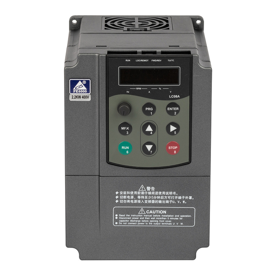
PE6000 User Manual Operation, Display and Application Examples 3 Operation, Display and Application Examples 3.1 Operation and Display Panel You can modify the parameters, monitor the working status and start or stop the PE6000 by operating the operation panel, as shown in the following figure. Figure 3-1 operation panel Forward /Reverse Forward /Reverse... -
Page 16: Viewing And Modifying Function Codes
Operation, Display and Application Examples PE6000 User Manual Hz: unit of frequency A: unit of current V: unit of voltage RPM (HZ+A): unit of rotational speed %( A+V): percentage Data Display The 5-digit LED display is able to display the set frequency, output frequency, monitoring data and fault codes. - Page 17 PE6000 User Manual Operation, Display and Application Examples Figure 3-2 Operation procedure on the operation panel Level-I menu Status parameter If there is a blinking digit, press (Select the function code group) (Default display) to modify the digit Switch BACK Level- II menu (Select the function code) BACK...
-
Page 18: Structure Of Function Codes
Operation, Display and Application Examples PE6000 User Manual 3.3 Structure of Function Codes PE6000 AC drive is new series vector type with good performance and strong function. Table 3-2 Structure of Function Codes Function Function Description Code Group Standard AC drive Standard function code of AC drive, which P0-PP function code group... -
Page 19: Definition And Operation Of The Multifunction Key (Mf.k)
PE6000 User Manual Operation, Display and Application Examples PP-02 is used to determine whether group A and group U are displayed. Function Code Parameter Name Setting Range Default Unit's digit (group U display selection) 0: Not display 1: Display AC drive parameter PP-02 display property Ten's digit (group A display selection) -
Page 20: Starting Or Stopping The Ac Drive
Operation, Display and Application Examples PE6000 User Manual Bit08: Linear speed Bit00: PID feedback Bit09: Current power-on Bit01: PLC stage time (Hour) Bit02: Pulse setting Bit10: Current running frequency (kHz) time (Minute) Bit03: Running frequency2 Bit11: Pulse setting LED display Bit04: Remaining running frequency (Hz) ☆... - Page 21 PE6000 User Manual Operation, Display and Application Examples 3.6.1.1 Operation Panel Control Operation panel control is on when you make P0-02=0 through keyboard operation After you press RUN the AC drive starts running (the RUN indicator is ON). After you press STOP when the AC drive is in running state, the AC drive stops running (the RUN indicator is OFF).
- Page 22 Operation, Display and Application Examples PE6000 User Manual `Figure 3-5 Setting of using the electromagnetic button for start/stop Command Function Terminal Setting value Terminal control source selection code Control switch Forward Forward Reverse Stop Running Stop Reverse command Terminal control Three-line mode 1 In the preceding figure, when SB1 is ON, the AC drive instructs forward rotation;...
- Page 23 PE6000 User Manual Operation, Display and Application Examples station protocol. 3.6.2 Start Mode The PE6000 supports three start modes, namely, direct start, rotational speed tracking restart, and pre-excited start (asynchronous motor), set in P6-00. P6-00 = 0 (direct start). It is applicable to small-inertia load. The frequency curve in this mode is shown in the following figure.
- Page 24 Operation, Display and Application Examples PE6000 User Manual Figure 3-9 Frequency curve of pre-excited start P0-12 P0-12 P6-00=2 P6-00=2 P6-07 P0-17 P6-03 = 0.00Hz P6-04 = 0.0s P0-17 P6-04 P6-07 = 0 P6-06 P6-06 P6-03 3.6.3 Stop Mode The AC drive supports two stop modes, decelerate to stop and coast to stop, set in P6-10. Figure 3-10 Diagram of two stop modes (decelerate to stop and coast to stop) Figure 3-10 Stop Modes P6-10 = 1...
- Page 25 PE6000 User Manual Operation, Display and Application Examples You can set the timing duration by means of analog input (such as potentiometer signal). For details, see the description of P8-43. 3.6.5 JOG Running In certain applications, the AC drive needs to run in low speed temporarily to facilitate equipment test or other commissioning operations.
-
Page 26: Setting The Running Frequency
Operation, Display and Application Examples PE6000 User Manual 3.6.5.2 Parameter Setting and Operation of JOG Running in DI Terminal Control For equipment that requires frequent JOG operations, such as textile machine, it is more convenient to control JOG running by using keys or buttons. To achieve convenient control, perform the setting according to the following figure. - Page 27 PE6000 User Manual Operation, Display and Application Examples 3.7.1 Frequency Setting by the Main Frequency Source There are nine setting modes of main frequency sources, digital setting (UP/DOWN modification, non-retentive at power failure), digital setting (UP/DOWN modification, retentive at power failure), AI1, AI2, AI3, pulse setting, multi-reference, simple PLC, and communication setting.
- Page 28 Operation, Display and Application Examples PE6000 User Manual 3.7.2 Frequency Setting by the Auxiliary Frequency Source The frequency setting by the auxiliary frequency source is the same as the frequency setting by the main frequency source. You can set the auxiliary frequency source in P0-04. Figure 3-16 Frequency set by the auxiliary frequency source Digital setting Retentive at...
- Page 29 PE6000 User Manual Operation, Display and Application Examples Figure 3-17 Relationship between the target running frequency and main and auxiliary frequency sources P0-07 P0-27 P0-27 P0-07 P0-05 P0-06 P4-00 to P4-09 = 18 P0-02 The operation between the main frequency source and the auxiliary frequency source can be used for closed-loop speed control.
- Page 30 Operation, Display and Application Examples PE6000 User Manual Figure 3-18 AI as the Frequency Source P4-33 = 1 P0-10 = 50.00Hz P0-07 = 0 P4-16 P4-13 = 0.00V P4-14 = 0.0% P4-15 = 10.00V P0-03 = 2 P4-16 = 100% P4-14 P4-17 = 0.1s P4-13...
- Page 31 PE6000 User Manual Operation, Display and Application Examples 3.7.5 Pulse Setting as the Frequency Source In many scenarios, pulse input is used as the frequency source. The specifications of pulse signals are: voltage 9–30 V, frequency 0–100 kHz. Only DI5 can be used for pulse input. The relationship between pulse input from DI5 and the corresponding setting is set in P4-28 to P4-31.
- Page 32 Operation, Display and Application Examples PE6000 User Manual as adjustment speed and accuracy, for the two units separately based on the actual conditions. Switchover between the two units can be implemented automatically or by means of an external DI terminal. 3.7.7 Swing Mode For the textile and chemical fiber processing equipment, the swing function improves the uniform density of traversing and winding, as shown in Figure 3-22.
- Page 33 PE6000 User Manual Operation, Display and Application Examples Operation, Display and Application Examples Figure 3-23 Setting the multi-speed function PC-00 P4-00 PC-01 P4-01 PC-02 P4-02 … P0-07 = 0 P4-03 PC-14 P0-27 = 0 P4-04 PC-15 P4-05 x (P0-10) P4-06 P0-03 = 6 P4-07 P4-08...
- Page 34 Operation, Display and Application Examples PE6000 User Manual Figure 3-24 Reversing the motor rotating direction P0-09 P8-13 If the command source is terminal control and reverse rotation is required, use the default value 0 of P8-13 to enable reverse control. According to the preceding figure, when the running frequency of the AC drive is set by means of communication (P0-03 = 9) and reverse control is enabled (P8-13 = 0), the AC drive instructs the reverse direction if the set frequency Fs is a negative value.
- Page 35 PE6000 User Manual Operation, Display and Application Examples Figure 3-25 Function code setting for fixed length control PB-05 P4-04 = 27 PB-07 P5-00 to P5-05 = 10 (Length pulses PB-06 (Length reached) input) P4-00 to P4-09 (Length reset) PB-05 = 11 PB-06 = 0 PB-06 = 11 Note...
- Page 36 Operation, Display and Application Examples PE6000 User Manual Figure 3-27 Parameter setting in the counting mode PB-09 (Designated counting value) P5-00 to P5-05 = 8 P4-00 to P4-09 (Designated counting = 25 value reached) (Counting pulses input) P5-00 to P5-05 = 9 PB-08 (Set counting value (Set counting)
-
Page 37: Setting And Auto-Tuning Of Motor Parameters
PE6000 User Manual Operation, Display and Application Examples 3.8 Setting and Auto-tuning of Motor Parameters 3.8.1 Motor Parameters to Be Set When the AC drive runs in the vector control mode (P0-01 = 0 or 1), accurate motor parameters are required to ensure desired driver performance and running efficiency. This is extremely different from the V/F control (P0-01 = 2). - Page 38 Operation, Display and Application Examples PE6000 User Manual The process of motor auto-tuning is as follows: The following motor auto-tuning description takes motor 1 as an example. The auto-tuning of motor 2, 3, and 4 is the same and only the function codes are changed correspondingly. 1.
-
Page 39: Use Of Di Terminals
PE6000 User Manual Operation, Display and Application Examples (Asynchronous motor static tuning) and then press RUN on the operation panel. The motor auto-tuning starts 3.9 Use of DI Terminals The control board provides five DI terminals DI1 to DI5. The internal hardware of DI terminals are configured with 24 VDC power supply for detection. You can input a signal to a DI terminal of the AC drive only by shorting the DI terminal and COM. -
Page 40: Use Of Do Terminals
Operation, Display and Application Examples PE6000 User Manual 3.10 Use of DO Terminals The control board provides three DO terminals, namely FM, DO1 and TA/TB/TC. FM and DO1 are transistor outputs and can drive 24 VDC low-voltage circuit; TA/TB/TC is relay output, and can drive 250 VAC control circuit. -
Page 41: Use Of Ao Terminals
PE6000 User Manual Operation, Display and Application Examples Operation, Display and Application Examples the voltage or current and actual setting or feedback is defined by P4-13 to P4-27. P3-29: AI curve selection The user can preset up to 5 curves. Different AIs can use one curve. -
Page 42: Use Of Serial Communication
Operation, Display and Application Examples PE6000 User Manual 3.13 Use of Serial Communication For the configuration of hardware communication parameters for the communication port, see • group PD. Set the communication rate and data format to consistent with those of the host computer, which is the precondition of normal communication. - Page 43 PE6000 User Manual Operation, Display and Application Examples The AC drive also provides the retentive function on alarm information and accumulative running time. You can restore the backup values or default settings of the function codes of the AC drive or clear the running data through PP-01.
-
Page 44: Function Code Tables
Function Code Tables PE6000 User Manual 4 Function Code Tables If PP-00 is set to a non-zero number, parameter protection is enabled. You must enter the correct user password to enter the menu. To cancel the password protection function, enter with password and set PP-00 to 0. Group P and Group A are standard function parameters. -
Page 45: Standard Function Parameters
PE6000 User Manual Function Code Tables 4.1 Standard Function Parameters Table 4.1 Standard Function Parameters Function Parameter Name Setting Range Default Modification Code Group P0: Standard Function Parameters 1: G type (constant torque load) Model ● P0-00 G/P type display 2: P type (variable torque load dependent e.g. - Page 46 Function Code Tables PE6000 User Manual Function Parameter Name Setting Range Default Modification Code Unit's digit (Frequency source selection) 0: Main frequency source X 1: X and Y operation (operation relationship determined by ten's digit) 2: Switchover between X and Y 3: Switchover between X and "X and Y operation"...
- Page 47 PE6000 User Manual Function Code Tables Function Parameter Name Setting Range Default Modification Code 0:1s Acceleration/Decelera ★ P0-19 1: 0.1s tion time unit 2: 0.01s Frequency offset of auxiliary frequency 0.00 Hz to maximum frequency ☆ P0-21 0.00 Hz source for X and Y (P0-10) operation Frequency reference...
- Page 48 Function Code Tables PE6000 User Manual Function Parameter Name Setting Range Default Modification Code Group P1: Motor Parameters 0: Common asynchronous motor ★ P1-00 Motor type selection 1: Variable frequency asynchronous motor Model ★ P1-01 Rated motor power 0.1–1000.0 kW dependent Model ★...
- Page 49 PE6000 User Manual Function Code Tables Group P2: Vector Control Parameters Function Parameter Name Setting Range Default Property Code Speed loop ☆ P2-00 0–100 proportional gain 1 Speed loop integral ☆ P2-01 0.01–10.00s 0.50s time 1 ☆ P2-02 Switchover frequency 1 0.00 to P2-05 5.00Hz Speed loop...
- Page 50 Function Code Tables PE6000 User Manual Function Parameter Name Setting Range Default Property Code Group P3: V/F Control Parameters 0: Linear V/F 1: Multi-point V/F 2: Square V/F 3: 1.2-power V/F 4: 1.4-power V/F ★ P3-00 V/F curve setting 6: 1.6-power V/F 8: 1.8-power V/F 9: Reserved 10: V/F complete separation...
- Page 51 PE6000 User Manual Function Code Tables Function Parameter Name Setting Range Default Property Code 0: Digital setting (P3-14) 1: AI1 2: AI2 3: Keyboard potentiometer 4: Pulse setting (DI5) Voltage source for V/F 5: Multi-reference ☆ P3-13 separation 6: Simple PLC 7: PID 8: Communication setting Note: 100.0% corresponds to the rated...
- Page 52 Function Code Tables PE6000 User Manual Function Parameter Setting Range Default Property Code Name Group F4: Input Terminals 0:No function 1:Forward RUN (FWD) 2:Reverse RUN (REV) 3:Three-line control 4:Forward JOG (FJOG) 5:Reverse JOG (RJOG) ★ P4-00 function 6:Terminal UP selection 7:Terminal DOWN 8:Coast to stop 9:Fault reset (RESET)
- Page 53 PE6000 User Manual Function Code Tables Function Parameter Name Setting Range Default Property Code ☆ P4-10 DI filter time 0.000–1.000s 0.010s 0: Two-line mode 1 1: Two-line mode 2 ★ P4-11 Terminal command mode 2: Three-line mode 1 3: Three-line mode 2 ☆...
- Page 54 Function Code Tables PE6000 User Manual Function Parameter Name Setting Range Default Property Code Unit's digit (AI1 curve selection) 1: Curve 1 (2 points, see P4-13 to P4-16) 2: Curve 2 (2 points, see P4-18 to P4-21) 3: Curve 3 (2 points, see P4-23 to P4-26) 4: Curve 4 (4 points, see A6-00 to A6-07) 5: Curve 5 (4 points, see A6-08 to A6-15) ☆...
- Page 55 PE6000 User Manual Function Code Tables Group F5: Output Terminals Function Parameter Name Setting Range Default Property Code FM terminal output 0: Pulse output (FMP) ☆ P5-00 mode 1: Switch signal output (FMR) FMR function 0: No output ☆ P5-01 (open- collector 1: AC drive running output terminal)
- Page 56 Function Code Tables PE6000 User Manual Function Parameter Name Setting Range Default Property Code 0: Running frequency 1:Set frequency 2:Output current 3: Output torque (absolute value) FMP function ☆ P5-06 4: Output power selection 5:Output voltage 6:Pulse input (100% corresponds 100.0kHz) 7: AI1 8: AI2 11: Count value...
- Page 57 PE6000 User Manual Function Code Tables Function Parameter Name Setting Range Default Property Code Startup DC braking ★ P6-05 current/ Pre-excited 0%–100% current Startup DC braking ★ P6-06 time/ Pre-excited 0.0–100.0s 0.0s time 0: Linear acceleration/ deceleration Acceleration/Deceler 1: S-curve acceleration/ deceleration A ★...
- Page 58 Function Code Tables PE6000 User Manual Group F7: Operation Panel and Display Function Parameter Name Setting Range Default Property Code 0: MF.K key disabled 1: Switchover between operation panel control and remote command control MF.K Key function (terminal or communication) ★...
- Page 59 PE6000 User Manual Function Code Tables Function Parameter Name Setting Range Default Property Code 0000–FFFF Bit00: Set frequency (Hz) Bit01: Bus voltage (V) Bit02: DI input status Bit03: DO output status Bit04: AI1 voltage (V) LED display stop Bit05: AI2 voltage (V) ☆...
- Page 60 Function Code Tables PE6000 User Manual Function Parameter Name Setting Range Default Property Code Model ☆ P8-06 Deceleration time 3 0.0–6500.0s dependent Model ☆ P8-07 Acceleration time 4 0.0–500.0s dependent Model ☆ P8-08 Deceleration time 4 0.0–6500.0s dependent ☆ P8-09 Jump frequency 1 0.00 Hz to maximum frequency 0.00 Hz...
- Page 61 PE6000 User Manual Function Code Tables Function Parameter Name Setting Range Default Property Code ☆ P8-27 Terminal JOG preferred 0: Disabled1: Enabled Frequency detection ☆ P8-28 0.00 to maximum frequency 50.00 Hz value (PDT2) Frequency detection ☆ P8-29 hysteresis (PDT 0.0%–100.0% (PDT2 level) 5.0% hysteresis 2)
- Page 62 Function Code Tables PE6000 User Manual Function Parameter Name Setting Range Default Property Code ☆ P8-50 Wakeup delay time 0.0–6500.0s 0.0s 0.00 Hz to wakeup frequency ☆ P8-51 Dormant frequency 0.00 Hz (P8-49) ☆ P8-52 Dormant delay time 0.0–6500.0s 0.0s Current running time ☆...
- Page 63 PE6000 User Manual Function Code Tables Function Parameter Setting Range Default Property Code Name 1: Reserved 2: Overcurrent during acceleration 3: Overcurrent during deceleration 4: Overcurrent at constant speed 5: Overvoltage during acceleration ● P9-14 1st fault type 6: Overvoltage during deceleration 7: Overvoltage at constant speed 8: Buffer resistance overload 9: Undervoltage...
- Page 64 Function Code Tables PE6000 User Manual Function Parameter Setting Range Default Property Code Name Power-on time ● P9-23 upon 3rd fault Running time ● P9-24 upon 3rd fault Frequency ● P9-27 upon 2nd fault Current upon ● P9-28 2nd fault Bus voltage ●...
- Page 65 PE6000 User Manual Function Code Tables Function Parameter Setting Range Default Property Code Name Unit's digit (Motor overload, Err11) 0: Coast to stop 1: Stop according to the stop mode 2: Continue to run Fault Ten's digit (Power input phase loss, Err12) protection ☆...
- Page 66 Function Code Tables PE6000 User Manual Function Parameter Name Setting Range Default Property Code ☆ PA-01 PID digital setting 0.0%–100.0% 50.0% 0: AI1 1: AI2 2: Keyboard potentiometer 3: AI1 – AI2 ☆ PA-02 PID feedback source 4: Pulse setting (DI5) 5: Communication setting 6: AI1 + AI2 7: MAX (|AI1|, |AI2|)
- Page 67 PE6000 User Manual Function Code Tables Function Parameter Name Setting Range Default Property Code PID initial value holding ☆ PA-22 0.00–650.00s 0.00s time Maximum deviation ☆ PA-23 between two PID outputs 0.00%–100.00% 1.00% in forward direction Maximum deviation ☆ PA-24 between two PID outputs 0.00%–100.00% 1.00%...
- Page 68 Function Code Tables PE6000 User Manual Group PC: Multi-Reference and Simple PLC Function Function Propert Parameter Name Setting Range Default Code ☆ PC-00 Reference 0 -100.0%–100.0% 0.0% ☆ PC-01 Reference 1 -100.0%–100.0% 0.0% ☆ PC-02 Reference 2 -100.0%–100.0% 0.0% ☆ PC-03 Reference 3 -100.0%–100.0%...
- Page 69 PE6000 User Manual Function Code Tables Function Propert Parameter Name Setting Range Default Code Running time of simple ☆ PC-20 0.0–6553.5s (h) 0.0s(h) PLC reference 1 Acceleration/deceleration ☆ PC-21 time of simple PLC 0–3 reference 1 Running time of simple 0.0s ☆...
- Page 70 Function Code Tables PE6000 User Manual Function Propert Parameter Name Setting Range Default Code Acceleration/deceleration ☆ PC-39 time of simple PLC 0–3 reference 10 Running time of simple ☆ PC-40 0.0–6553.5s (h) 0.0s(h) PLC reference 11 Acceleration/deceleration ☆ PC-41 time of simple PLC 0–3 reference 11 Running time of simple...
- Page 71 PE6000 User Manual Function Code Tables Group PD: Communication Parameters Function Propert Parameter Name Setting Range Default Code Unit's digit (Modbus baud rate) 0: 300 BPs 1: 600 BPs 2: 1200 BPs Baud rate 3: 2400 BPs ☆ PD-00 4: 4800 BPs 5: 9600 BPs 6: 19200 BPs 7: 38400 BPs...
- Page 72 Function Code Tables PE6000 User Manual Function Propert Parameter Name Setting Range Default Code Unit's digit (Group U display selection) 0: Not display AC drive parameter 1: Display ★ PP-02 display property Ten's digit (Group A display selection) 0: Not display Parameter modification 0: Modifiable ☆...
- Page 73 PE6000 User Manual Function Code Tables Function Parameter Name Setting Range Default Property Code ☆ A5-04 Rapid current limit 0: Disabled1: Enabled Current detection ☆ A5-05 0–100 compensation ☆ A5-06 Undervoltage threshold 60.0%–140.0% 100.0% SVC optimization mode 0: No optimization ☆...
- Page 74 Function Code Tables PE6000 User Manual Function Parameter Name Setting Range Default Property Code Jump amplitude of AI1 input ☆ A6-25 0.0%–100.0% 0.5% corresponding setting Jump point of AI2 input ☆ A6-26 -100.0%–100.0% 0.0% corresponding setting Jump amplitude of AI2 input ☆...
-
Page 75: Monitoring Parameters
PE6000 User Manual Function Code Tables Function Parameter Name Setting Range Default Property Code Factory ☆ AC-12 AO1 target voltage 1 0.500–4.000 V corrected Factory ☆ AC-13 AO1 measured voltage 1 0.500–4.000 V corrected Factory ☆ AC-14 AO1 target voltage 2 6.000–9.999 V corrected Factory... - Page 76 Function Code Tables PE6000 User Manual Function Communication Parameter Name Min. Unit Code Address U0-18 Input pulse frequency (Hz) 0.01 kHz 7012H U0-19 Feedback speed (0.1Hz) 0.1 Hz 7013H U0-20 Remaining running time 0.1 Min 7014H U0-21 AI1 voltage before correction 0.001 V 7015H U0-22...
-
Page 77: Description Of Function Codes
PE6000 User Manual Description of Function Codes 5 Description of Function Codes Group P0: Basic Parameters Function Parameter Name Setting Range Default Code 1: G type (constant torque load) Model P0-00 G/P type display 2: P type (variable torque load e.g. fan dependent and pump) This parameter is used to display the delivered model and cannot be modified. - Page 78 Description of Function Codes PE6000 User Manual Function Parameter Name Setting Range Default Code 0: Operation panel control (LED off) Command P0-02 1: Terminal control (LED on) source selection 2: Communication control (LED blinking) It is used to determine the input channel of the AC drive control commands, such as run, stop, forward rotation, reverse rotation and jog operation.
- Page 79 PE6000 User Manual Description of Function Codes change the set frequency by pressing on the operation panel (or using the UP/DOWN functions of input terminals). When the AC drive is powered on again after power failure, the set frequency reverts to the value of P0-08.
- Page 80 Description of Function Codes PE6000 User Manual You can set the relationship between pulse frequency of DI5 and corresponding settings through P4-28 to P4-31. The mapping relationship is linear (point-point) correspondence. The corresponding value 100% of pulse setting corresponds to the value of P0-10 (Maximum frequency).
- Page 81 PE6000 User Manual Description of Function Codes take effect. You can directly adjust the set main frequency by pressing keys on the operation panel (or using the UP/DOWN function of input terminals). If the auxiliary frequency source is analog input (AI1, AI2 and Keyboard potentiometer) or •...
- Page 82 Description of Function Codes PE6000 User Manual Function Parameter Name Setting Range Default Code Ten's digit (X and Y operation relationship) 0: X+Y Frequency source 1: X-Y P0-07 selection 2: Maximum 3: Minimum 4. X×Y It is used to select the frequency setting channel. If the frequency source involves X and Y operation, you can set the frequency offset in P0-21 for superposition to the X and Y operation result, flexibly satisfying various requirements.
- Page 83 PE6000 User Manual Description of Function Codes Function Parameter Name Setting Range Default Code 0: Same direction P0-09 Rotation direction 1: Reverse direction You can change the rotation direction of the motor just by modifying this parameter without changing the motor wiring. Modifying this parameter is equivalent to exchanging any two of the motor's U, V, W wires.
- Page 84 Description of Function Codes PE6000 User Manual It is used to set the source of the frequency upper limit, including digital setting (P0-12), AI, pulse setting or communication setting. If the frequency upper limit is set by means of AI1, AI2, Keyboard potentiometer, DI5 or communication, the setting is similar to that of the main frequency source X.
- Page 85 PE6000 User Manual Description of Function Codes If the carrier frequency is low, output current has high harmonics, and the power loss and temperature rise of the motor increase. If the carrier frequency is high, power loss and temperature rise of the motor declines. However, the AC drive has an increase in power loss, temperature rise and interference.
- Page 86 Description of Function Codes PE6000 User Manual Acceleration time indicates the time required by the AC drive to accelerate from 0 Hz to "Acceleration/Deceleration base frequency" (P0-25), that is, t1 in Figure 5-1. Deceleration time indicates the time required by the AC drive to decelerate from "Acceleration/Deceleration base frequency"...
- Page 87 PE6000 User Manual Description of Function Codes Function Parameter Name Setting Range Default Code Frequency offset of auxiliary frequency 0.00 Hz to maximum P0-21 0.00Hz source for X and Y operation frequency (P0-10) This parameter is valid only when the frequency source is set to "X and Y operation". The final frequency is obtained by adding the frequency offset set in this parameter to the X and Y operation result Function...
- Page 88 Description of Function Codes PE6000 User Manual To satisfy requirements of different applications, the PE6000 provides two output selections of 0Hz, Yes and No. Function Parameter Name Setting Range Default Code 0: Maximum frequency (P0-10) Acceleration/Deceleration time P0-25 1: Set frequency base frequency 2: 100 Hz The acceleration/deceleration time indicates the time for the AC drive to increase from 0 Hz to...
-
Page 89: Group P1: Motor Parameters
PE6000 User Manual Description of Function Codes It is used to bind the three running command sources with the nine frequency sources, facilitating to implement synchronous switchover. For details on the frequency sources, see the description of P0-03 (Main frequency source X selection). - Page 90 Description of Function Codes PE6000 User Manual Function Parameter Name Setting Range Default Code 0.001–65.535 Ω (AC drive power ≤ 55 Stator resistance Model kW) 0.0001–6.5535 Ω (AC drive power > P1-06 (asynchronous motor) dependent 55 kW) 0.001–65.535 Ω (AC drive power ≤ 55 Rotor resistance Model kW) 0.0001–6.5535 Ω...
- Page 91 PE6000 User Manual Description of Function Codes asynchronous motor cannot be disconnected from the load. Before performing static auto-tuning, properly set the motor type and motor nameplate parameters of P1-00 to P1-05 first. The AC drive will obtain parameters of P1-06 to P1- 08 by static auto-tuning. Set this parameter to 1, and press RUN.
-
Page 92: Group P2: Vector Control Parameters
Description of Function Codes PE6000 User Manual Group P2: Vector Control Parameters Group P2 is valid for vector control, and invalid for V/F control. Function Parameter Name Setting Range Default Code P2-00 Speed loop proportional gain 1 1–100 P2-01 Speed loop integral time 1 0.01–10.00s 0.50s P2-02... - Page 93 PE6000 User Manual Description of Function Codes To achieve a faster system response, increase the proportional gain and reduce the integral time. Be aware that this may lead to system oscillation. The recommended adjustment method is as follows: If the factory setting cannot meet the requirements, make proper adjustment. Increase the proportional gain first to ensure that the system does not oscillate, and then reduce the integral time to ensure that the system has quick response and small overshoot.
- Page 94 Description of Function Codes PE6000 User Manual avoid the overvoltage fault. The larger the over-excitation gain is, the better the restraining effect is. Increase the over-excitation gain if the AC drive is liable to overvoltage error during deceleration. Too large over-excitation gain, however, may lead to an increase in output current. Therefore, set this parameter to a proper value in actual applications.
-
Page 95: Group P3: V/F Control Parameters
PE6000 User Manual Description of Function Codes These are current loop PI parameters for vector control. These parameters are automatically obtained through "Asynchronous motor complete auto-tuning" or "Synchronous motor no- load auto-tuning", and need not be modified. The dimension of the current loop integral regulator is integral gain rather than integral time. Note that too large current loop PI gain may lead to oscillation of the entire control loop. - Page 96 Description of Function Codes PE6000 User Manual It is applicable to induction heating, inverse power supply and torque motor control. 11: V/F half separation • In this mode, V and F are proportional and the proportional relationship can be set in P3-13. The relationship between V and F are also related to the rated motor voltage and rated motor frequency in Group P1.
- Page 97 PE6000 User Manual Description of Function Codes Function Parameter Name Setting Range Default Code P3-03 Multi-point V/F frequency 1 (F1) 0.00 Hz to P3-05 0.00 Hz P3-04 Multi-point V/F voltage 1 (V1) 0.0%–100.0% 0.0% P3-05 Multi-point V/F frequency 2 (F2) P3-03 to P3-07 0.00 Hz P3-06...
- Page 98 Description of Function Codes PE6000 User Manual It can compensate the rotational speed slip of the asynchronous motor when the load of the motor increases, stabilizing the motor speed in case of load change. If this parameter is set to 100%, it indicates that the compensation when the motor bears rated load is the rated motor slip.
- Page 99 PE6000 User Manual Description of Function Codes Function Parameter Name Setting Range Default Code 0: Digital setting (F3-14) 1: AI1 2: AI2 3: Keyboard potentiometer 4: Pulse setting (DI5) Voltage source for V/F P3-13 5: Multi-reference separation 6: Simple PLC 7: PID 8: Communication setting 100.0% corresponds to the rated motor voltage...
-
Page 100: Group P4: Input Terminals
Description of Function Codes PE6000 User Manual 8: Communication setting • The output voltage is set by the host computer by means of communication. The voltage source for V/F separation is set in the same way as the frequency source. For details, see P0-03. - Page 101 PE6000 User Manual Description of Function Codes The following table lists the functions available for the DI terminals. Table 6-1 Functions of DI terminals Value Function Description No function Set 0 for reserved terminals to avoid malfunction. Forward RUN (FWD) The terminal is used to control forward or reverse RUN of the AC drive.
- Page 102 Description of Function Codes PE6000 User Manual Value Function Description Terminal 1 for acceleration/ deceleration Totally four groups of acceleration/deceleration time time selection can be selected through combinations of four states of these two terminals. For details please refer to the Terminal 2 for Appendix table 2.
- Page 103 PE6000 User Manual Description of Function Codes Value Function Description Frequency modification After this terminal becomes ON, the AC drive does not forbidden respond to any frequency modification. Reverse PID action After this terminal becomes ON, the PID action direction direction is reversed to the direction set in PA-03.
- Page 104 Description of Function Codes PE6000 User Manual Value Function Description When this terminal becomes ON, the AC drive Deceleration DC braking decelerates to the initial frequency of stop DC braking and then switches over to DC braking state. When this terminal becomes ON, the AC drive's current Clear the current running running time is cleared.
- Page 105 PE6000 User Manual Description of Function Codes different setting values. Two terminals for acceleration/deceleration time selection have four state combinations, as listed in the following table. The following table states combinations of two terminals for acceleration/deceleration time selection Acceleration/Deceleration Time Corresponding Terminal 2 Terminal 1 Selection...
- Page 106 Description of Function Codes PE6000 User Manual Function Parameter Name Setting Range Default Code 0: Two-line mode 1 1: Two-line mode 2 P4-11 Terminal command mode 2: Three-line mode 1 3: Three-line mode 2 This parameter is used to set the mode in which the AC drive is controlled by external terminals.
- Page 107 PE6000 User Manual Description of Function Codes Function Parameter Name Value Function Description Code P4-11 Terminal command mode Two-line 2 P4-00 DI1 function selection RUN enabled Forward or reverse P4-01 DI2 function selection direction Figure 5-7 Setting of two-line mode 2 PE6000 As shown in the preceding figure, if K1 is ON, the AC drive instructs forward rotation when K2 is OFF, and instructs reverse rotation when K2 is ON.
- Page 108 Description of Function Codes PE6000 User Manual Figure 5-8 Setting of three-line mode 1 PE6000 As shown in the preceding figure, if SB1 is ON, the AC drive instructs forward rotation when SB2 is pressed to be ON and instructs reverse rotation when SB3 is pressed to be ON. The AC drives stops immediately after SB1 becomes OFF.
- Page 109 PE6000 User Manual Description of Function Codes Figure 5-9 Setting of three-line mode 2 PE6000 As shown in the preceding figure, if SB1 is ON, the AC drive starts running when SB2 is pressed to be ON; the AC drive instructs forward rotation when K is OFF and instructs reverse rotation when K is ON.
- Page 110 Description of Function Codes PE6000 User Manual corresponding setting. When the analog input voltage exceeds the maximum value (P4- 15), the maximum value is used. When the analog input voltage is less than the minimum value (P4-13), the value set in P4-34 (Setting for AI less than minimum input) is used. When the analog input is current input, 1mA current corresponds to 0.5 V voltage.
- Page 111 PE6000 User Manual Description of Function Codes Function Parameter Name Setting Range Default Code P4-18 AI curve 2 minimum input 0.00 V to P4-20 0.00 V Corresponding setting of AI curve 2 P4-19 -100.00%–100.0% 0.0% minimum input P4-20 AI curve 2 maximum input P4-18 to 10.00 V 10.00 V Corresponding setting of AI curve 2...
- Page 112 Description of Function Codes PE6000 User Manual the corresponding curve of AI1, AI2 and AI3. Any of the five curves can be selected for AI1, AI2 and AI3. Curve 1, curve 2 and curve 3 are all 2-point curves, set in group F4. Curve 4 and curve 5 are both 4-point curves, set in group A6.
-
Page 113: Group P5: Output Terminals
PE6000 User Manual Description of Function Codes Function Parameter Name Setting Range Default Code Unit's digit (DI1 valid mode) 0: High level valid 1: Low level valid Ten's digit (DI2 valid mode) 0, 1 (same as DI1) Hundred's digit (DI3 valid mode) P4-38 DI valid mode selection 1 00000... - Page 114 Description of Function Codes PE6000 User Manual These three parameters are used to select the functions of the three digital output terminals. T/A-T/B-T/C and P/A-P/B-P/C are respectively the relays on the control board and the extension card. The functions of the output terminals are described in the following table Table Functions of output terminals Value Function...
- Page 115 PE6000 User Manual Description of Function Codes Value Function Description If the AC drive main circuit and control circuit become Ready for RUN stable, and the AC drive detects no fault and is ready for RUN, the terminal becomes ON. When the input of AI1 is larger than the input of AI2, the AI1 larger than AI2 terminal becomes ON.
- Page 116 Description of Function Codes PE6000 User Manual Value Function Description Frequency lower limit If the running frequency reaches the lower limit, the reached (having terminal becomes ON. In the stop state, the signal is still output at stop) If a fault occurs on the AC drive and the AC drive Alarm output continues to run, the terminal outputs the alarm signal.
- Page 117 PE6000 User Manual Description of Function Codes Range (Corresponding to Pulse or Analog Value Function Output Range 0.0%–100.0%) 0 to rotational speed corresponding to Motor rotational speed maximum output frequency Output current 0.0–1000.0 A Output voltage 0.0–1000.0 V -2 times of rated motor torque to 2 times of Output torque (actual value) rated motor torque Function...
-
Page 118: Group P6: Start/Stop Control
Description of Function Codes PE6000 User Manual Group P6: Start/Stop Control Function Parameter Name Setting Range Default Code 0: Direct start 1: Rotational speed P6-00 Start mode tracking restart 2: Pre-excited start (asynchronous motor) 0: Direct start • If the DC braking time is set to 0, the AC drive starts to run at the startup frequency. If the DC braking time is not 0, the AC drive performs DC braking first and then starts to run at the startup frequency. - Page 119 PE6000 User Manual Description of Function Codes state. During switchover between forward rotation and reverse rotation, the startup frequency holding time is disabled. The holding time is not included in the acceleration time but in the running time of simple PLC. Example 1: P0-03 = 0 The frequency source is digital setting.
- Page 120 Description of Function Codes PE6000 User Manual the startup DC braking time is 0, the AC drive starts directly without DC braking. The larger the startup DC braking current is, the larger the braking force is. If the startup mode is pre-excited start, the AC drive builds magnetic field based on the set pre-excited current.
- Page 121 PE6000 User Manual Description of Function Codes Function Parameter Name Setting Range Default Code Time proportion of S-curve start P6-08 0.0% to (100.0% – P6-09) 30.0% segment Time proportion of S-curve end P6-09 0.0% to (100.0% – P6-08) 30.0% segment These two parameters respectively define the time proportions of the start segment and the end segment of S-curve acceleration/deceleration.
- Page 122 Description of Function Codes PE6000 User Manual Function Parameter Name Setting Range Default Code 0: Decelerate to top P6-10 Stop mode 1: Coast to stop 0: Decelerate to stop • After the stop command is enabled, the AC drive decreases the output frequency according to the deceleration time and stops when the frequency decreases to zero.
- Page 123 PE6000 User Manual Description of Function Codes Function Parameter Name Setting Range Default Code P6-15 Brake use ratio 0%–100% 100% It is valid only for the AC drive with internal braking unit and used to adjust the duty ratio of the braking unit.
-
Page 124: Group P7: Operation Panel And Display
Description of Function Codes PE6000 User Manual Group P7: Operation Panel and Display Function Parameter Name Setting Range Default Code 0: MF.K key disabled 1: Switchover between operation panel control and remote command control MF.K Key function (terminal or communication) P7-01 selection 2: Switchover between forward rotation... - Page 125 PE6000 User Manual Description of Function Codes Function Parameter Setting Range Default Code Name 0000-FFFF Running frequency1 (Hz) Set frequency (Hz) Bus voltage (V) Output voltage (V) Output current (A) Output power (kW) Output torque (%) DI input status P7-03 001F DO output status AI1 voltage (V)
- Page 126 Description of Function Codes PE6000 User Manual Function Parameter Setting Range Default Code Name 0000-FFFF Set frequency (Hz) Bus voltage (V) DI input status DO output status AI1 voltage (V) AI2 voltage (V) AI3 voltage (V) Count value P7-05 0000 Length value PLC stage Load speed...
- Page 127 PE6000 User Manual Description of Function Codes Function Parameter Name Setting Range Default Code P7-09 Accumulative running time 0–65535 h It is used to display the accumulative running time of the AC drive. After the accumulative running time reaches the value set in P8-17, the terminal with the digital output function 12 becomes ON.
-
Page 128: Group P8: Auxiliary Functions
Description of Function Codes PE6000 User Manual state is 50.00 x 2.000 = 100.00 (display of 2 decimal places). Function Parameter Name Setting Range Default Code P7-13 Accumulative power-on time 0–65535 h It is used to display the accumulative power-on time of the AC drive since the delivery. If the time reaches the set power-on time (P8-17), the terminal with the digital output function 24 becomes ON. - Page 129 PE6000 User Manual Description of Function Codes Setting Range 0.00 Hz to maximum frequency Acceleration time 4 Default 20.0s P8-07 Setting Range 0.0–6500.0s Acceleration time 4 Default 20.0s P8-08 Setting Range 0.0–6500.0s The PE6000 provides a total of four groups of acceleration/deceleration time, that is, the preceding three groups and the group defined by F0-17 and F0-18.
- Page 130 Description of Function Codes PE6000 User Manual Forward/Reverse rotation Default 0.00s dead-zone time P8-12 Setting Range 0.0–3000.0s It is used to set the time when the output is 0 Hz at transition of the AC drive forward rotation and reverse rotation, as shown in the following figure.
- Page 131 PE6000 User Manual Description of Function Codes Figure 5-15 Forward/Reverse rotation dead-zone time Reverse control Default P8-13 Enabled Setting Range Disabled It is used to set whether the AC drive allows reverse rotation. In the applications where reverse rotation is prohibited, set this parameter to P8-13=1. Running mode when set frequency lower than Default...
- Page 132 Description of Function Codes PE6000 User Manual For example, combining virtual DI/DO functions, to implement the function that the AC drive reports an alarm when the actual accumulative power-on time reaches the threshold of 100 hours, perform the setting as follows: Set virtual DI1 to user-defined fault 1: A1-00 = 44.
- Page 133 PE6000 User Manual Description of Function Codes Frequency detection Default 5.0% hysteresis (FDT hysteresis 1) P8-20 Setting Range 0.0%–100.0% (FDT1 level) If the running frequency is higher than the value of P8-19, the corresponding DO terminal becomes ON. If the running frequency is lower than value of P8-19, the DO terminal goes OFF These two parameters are respectively used to set the detection value of output frequency and hysteresis value upon cancellation of the output.
- Page 134 Description of Function Codes PE6000 User Manual If the AC drive running frequency is within the certain range of the set frequency, the corresponding DO terminal becomes ON. This parameter is used to set the range within which the output frequency is detected to reach the set frequency.
- Page 135 PE6000 User Manual Description of Function Codes Frequency switchover point between acceleration time 1 Default 0.00 Hz P8-25 and acceleration time 2 Setting Range 0.00 Hz to maximum frequency Frequency switchover point between deceleration time 1 Default 0.00Hz P8-26 and deceleration time 2 Setting Range 0.00 Hz to maximum frequency This function is valid when motor 1 is selected and acceleration/deceleration time switchover is...
- Page 136 Description of Function Codes PE6000 User Manual P8-25 P8-26 During acceleration, if the running frequency is smaller than the value of P8-25, acceleration time 2 is selected. If the running frequency is larger than the value of P8-25, acceleration time 1 is selected.
- Page 137 PE6000 User Manual Description of Function Codes descriptions of P8-19 and P8-20. Any frequency reaching Default 50.00 Hz detection value 1 P8-30 Setting Range 0.00 Hz to maximum frequency Any frequency reaching Default 0.0% detection amplitude 1 P8-31 Setting Range 0.0%–100.0% (maximum frequency) Any frequency reaching Default...
- Page 138 Description of Function Codes PE6000 User Manual If the output current of the AC drive is equal to or less than the zero current detection level and the duration exceeds the zero current detection delay time, the corresponding DO becomes ON. The zero current detection is shown in the following figure.
- Page 139 PE6000 User Manual Description of Function Codes P8-36 P8-37 Any current reaching 1 Default 100.0% P8-38 Setting Range 0.0%–300.0% (rated motor current) Any current reaching 1 amplitude Default 0.0% P8-39 Setting Range 0.0%–300.0% (rated motor current) Any current reaching 2 Default 100.0% P8-40...
- Page 140 Description of Function Codes PE6000 User Manual Timing function Default P8-42 Disabled Setting Range Enabled Timing duration source Default 0.0Min P8-44 Setting Range 0.0–6500.0 Min These parameters are used to implement the AC drive timing function. If P8-42 is set to 1, the AC drive starts to time at startup. When the set timing duration is reached, the AC drive stops automatically and meanwhile the corresponding DO becomes ON.
- Page 141 PE6000 User Manual Description of Function Codes Setting Range 0.00 V - P8-46 When the heatsink temperature of the AC drive reaches the value of this parameter, the corresponding DO becomes ON, indicating that the module temperature reaches the threshold. Wakeup frequency Default 0.00Hz...
-
Page 142: Group F9: Fault And Protection
Description of Function Codes PE6000 User Manual Group F9: Fault and Protection Motor overload protection Default selection P9-00 Disabled Setting Range Enabled Motor overload protection gain Default 1.00 P9-01 Setting Range 0.20–10.00 Ÿ P9-00 =0 The motor overload protective function is disabled. The motor is exposed to potential damage due to overheating. - Page 143 PE6000 User Manual Description of Function Codes Overvoltage stall gain Default P9-03 Setting Range 0 (no stall overvoltage)–100 Overvoltage stall protective voltage Default 130% P9-04 Setting Range 120% - 150% When the DC bus voltage exceeds the value of P9-04 (Overvoltage stall protective voltage) during deceleration of the AC drive, the AC drive stops deceleration and keeps the present running frequency.
- Page 144 Description of Function Codes PE6000 User Manual (P9-06), the output current declines during acceleration of the AC drive; the output current declines if the AC drive runs at constant speed; the falling speed declines during deceleration of the AC drive. The running frequency returns to normal until the output current is less than the overcurrent stall protective current (P9-06).
- Page 145 PE6000 User Manual Description of Function Codes Short-circuit to ground upon power- on Default P9-07 Disabled Setting Range Enabled It is used to determine whether to check the motor is short-circuited to ground at power-on of the AC drive. If this function is enabled, the AC drive's UVW will have voltage output a while after power-on. Fault auto reset times Default P9-09...
- Page 146 Description of Function Codes PE6000 User Manual Output phase loss protection selection Default P9-13 Disabled Setting Range Enabled It is used to determine whether to perform output phase loss protection. P9-14 1st fault type P9-15 2nd fault type 0-99 P9-16 3nd (last time) fault type It is used to record the types of the most recent three faults of the AC drive.
- Page 147 PE6000 User Manual Description of Function Codes P9-27 Frequency upon 2nd fault P9-28 Current upon 2nd fault P9-29 Bus voltage upon 2nd fault P9-30 DI status upon 2nd fault Same as P9-17–P9-24. Output terminal status P9-31 upon 2nd fault P9-32 Frequency upon 2nd fault P9-33 Current upon 2nd fault...
- Page 148 Description of Function Codes PE6000 User Manual Frequency selection for Default continuing to run upon fault Current running frequency Set frequency P9-54 Frequency upper limit Setting Range Frequency lower limit Backup frequency upon abnormality Backup frequency upon Default 100.0% abnormality P9-55 Setting Range 0.0%-100.0%...
- Page 149 PE6000 User Manual Description of Function Codes continuously. If P9-59 = 1, upon instantaneous power failure or sudden voltage dip, the AC drive decelerates. • Once the bus voltage resumes to normal, the AC drive accelerates to the set frequency. If the bus voltage remains normal for the time exceeding the value set in P9-61, it is considered that the bus voltage resumes to normal.
-
Page 150: Group Pa: Process Control Pid Function
Description of Function Codes PE6000 User Manual Protection upon load Default becoming 0 P9-63 Invalid Setting Range Decelerate Detection level of load Default 10.0% becoming 0 P9-64 Setting Range 0.0%–100.0% (rated motor current) Detection time of load Default 1.0s becoming 0 P9-65 Setting Range 0.0s–60.0s... - Page 151 PE6000 User Manual Description of Function Codes Function Parameter Name Setting Range Default Code 0: FA-01 1: AI1 2: AI2 PA-00 PID setting source 3: potentiometer 4: Pulse setting (DI5) 5: Communication setting 6: Multi-reference PA-01 PID digital setting 0.0%–100.0% 50.0% This parameter is used to select the channel of target process PID setting.
- Page 152 Description of Function Codes PE6000 User Manual Function Parameter Name Setting Range Default Code PA-04 PID setting feedback range 0–65535 1000 This parameter is a non-dimensional unit. It is used for PID setting display (U0-15) and PID feedback display (U0-16). Relative value 100% of PID setting feedback corresponds to the value of PA-04.
- Page 153 PE6000 User Manual Description of Function Codes In some situations, only when the PID output frequency is a negative value (AC drive reverse rotation), PID setting and PID feedback can be equal. However, too high reverse rotation frequency is prohibited in some applications, and PA-08 is used to determine the reverse rotation frequency upper limit.
- Page 154 Description of Function Codes PE6000 User Manual Function Parameter Name Setting Range Default Code PA-15 Proportional gain Kp2 0.0–100.0 20.0 PA-16 Integral time Ti2 0.01–10.00s 2.00s PA-17 Differential time Td2 0.000–10.000s 0.000s 0: No switchover PID parameter switchover 1: Switchover via DI PA-18 condition 2: Automatic switchover based...
- Page 155 PE6000 User Manual Description of Function Codes Function Parameter Name Setting Range Default Code PA-21 PID initial value 0.0%–100.0% 0.0% PA-22 PID initial value holding time 0.00–650.00s 0.00s When the AC drive starts up, the PID starts closed-loop algorithm only after the PID output is fixed to the PID initial value (PA-21) and lasts the time set in PA-22.
- Page 156 Description of Function Codes PE6000 User Manual Function Parameter Name Setting Range Default Code Unit's digit (Integral separated) 0: Invalid 1: Valid PA-25 PID integral property Ten's digit (Whether to stop integral operation when the output reaches the limit) 0: Continue integral operation 1: Stop integral operation Integral separated •...
-
Page 157: Group Pb: Swing Frequency, Fixed Length And Count
PE6000 User Manual Description of Function Codes Group PB: Swing Frequency, Fixed Length and Count The swing frequency function is applied to the textile and chemical fiber fields and the applications where traversing and winding functions are required. The swing frequency function indicates that the output frequency of the AC drive swings up and down with the set frequency as the center. - Page 158 Description of Function Codes PE6000 User Manual Function Parameter Name Setting Range Default Code PB-01 Swing frequency amplitude 0.0%–100.0% 0.0% PB-02 Jump frequency amplitude 0.0%–50.0% 0.0% This parameter is used to determine the swing amplitude and jump frequency amplitude. If relative to the central frequency (PB-00 = 0), the actual swing amplitude AW is the calculation result of F0-07 (Frequency source selection) multiplied by PB-01.
- Page 159 PE6000 User Manual Description of Function Codes dividing the number of pulses collected by the DI terminal by PB-07 (Number of pulses each meter). When the actual length PB-06 exceeds the set length in PB-05, the DO terminal allocated with function 10 (Length reached) becomes ON.
-
Page 160: Group Pc: Multi-Reference And Simple Plc Function
Description of Function Codes PE6000 User Manual Group PC: Multi-Reference and Simple PLC Function The PE6000 multi-reference has many functions. Besides multi-speed, it can be used as the setting source of the V/F separated voltage source and setting source of process PID. In addition, the multi-reference is relative value. - Page 161 PE6000 User Manual Description of Function Codes Multi-reference can be switched over based on different states of DI terminals. For details, see the descriptions of group F4. Function Parameter Name Setting Range Default Code 0: Stop after the AC drive runs one cycle Simple PLC running 1: Keep final values after the AC drive runs PC-16...
- Page 162 Description of Function Codes PE6000 User Manual receiving the stop command. Function Parameter Name Setting Range Default Code Unit's digit (Retentive upon power failure) 0: No 1: Yes Simple PLC retentive PC-17 selection Ten's digit (Retentive upon stop) 0: No 1: Yes PLC retentive upon power failure indicates that the AC drive memorizes the PLC running moment and running frequency before power failure and will continue to run from the memorized...
- Page 163 PE6000 User Manual Description of Function Codes Function Parameter Name Setting Range Default Code Acceleration/deceleration time of simple PLC PC-29 0–3 reference 5 PC-30 Running time of simple PLC reference 6 0.0–6553.5s (h) 0.0s (h) Acceleration/deceleration time of simple PLC PC-31 0–3 reference 6...
-
Page 164: Group Pd Communication Parameters
Description of Function Codes PE6000 User Manual Function Parameter Name Setting Range Default Code 0: Set by PC-00 1: AI1 2: AI2 3: potentiometer PC-51 Reference 0 source 4: Pulse setting 5: PID 6: Set by preset frequency (P0-08), modified via terminal UP/DOWN It determines the setting channel of reference 0. - Page 165 PE6000 User Manual Description of Function Codes 2. Clear records If PP-01 is set to 2, the fault records, accumulative running time (P7-09), accumulative power-on time (P7-13) and accumulative power consumption (P7-14) are cleared. 3. Back up current user parameters Back up current user parameters and the current parameter settings are backed up, helping you to restore the setting if incorrect parameter setting is performed.
-
Page 166: Group A0: Torque Control And Restricting Parameters
Description of Function Codes PE6000 User Manual Parameter modification property Default PP-04 Modifiable Setting Range Not modifiable It is used to set whether the parameters are modifiable to avoid mal-function. If it is set to 0, all parameters are modifiable. If it is set to 1, all parameters can only be viewed. Group A0: Torque Control and Restricting Parameters Speed/Torque control selection Default... - Page 167 PE6000 User Manual Description of Function Codes drive's rated torque. If the torque setting is positive, the AC drive rotates in forward direction. If the torque setting is negative, the AC drive rotates in reverse direction. 0: Digital setting (A0-03) •...
- Page 168 Description of Function Codes PE6000 User Manual Forward maximum frequency in torque Default 50.00 Hz control A0-05 Setting Range 0.00 Hz to maximum frequency (P0-10) Reverse maximum frequency in torque Default 50.00 Hz control A0-06 Setting Range 0.00 Hz to maximum frequency (P0-10) The two parameters are used to set the maximum frequency in forward or reverse rotation in torque control mode.
-
Page 169: Group A5: Control Optimization Parameters
PE6000 User Manual Description of Function Codes Group A5: Control Optimization Parameters DPWM switch over frequency upper limit Default 12.00 Hz A5-00 Setting Range 0.00–15.00 Hz This parameter is valid only for V/F control. It is used to determine the wave modulation mode in V/F control of asynchronous motor. If the frequency is lower than the value of this parameter, the waveform is 7-segment continuous modulation. - Page 170 Description of Function Codes PE6000 User Manual Dead zone compensation mode Default No compensation A5-02 Setting Range Compensation mode 1 Compensation mode 2 Generally, you need not modify this parameter. Try to use a different compensation mode only when there is special requirement on the output voltage waveform quality or oscillation occurs on the motor.
- Page 171 PE6000 User Manual Description of Function Codes It is used to set the undervoltage threshold of Err09. The undervoltage threshold 100% of the AC drive of different voltage classes corresponds to different nominal values, as listed in the following table. Voltage Class Nominal Value of Undervoltage threshold Single-phase 220 V...
-
Page 172: Group A6: Ai Curve Setting
Description of Function Codes PE6000 User Manual It is used to set the overvoltage threshold of the AC drive. The default values of different voltage classes are listed in the following table. Voltage Class Default Overvoltage Threshold Single-phase 220 V 400.0 V Three-phase 220 V 400.0 V... - Page 173 PE6000 User Manual Description of Function Codes AI curve 4 maximum input Default 10.00 V A6-06 Setting Range A6-06 to 10.00 V Corresponding setting of AI curve 4 Default 100.0% maximum input A6-07 Setting Range -100.0%–100.0% AI curve 5 minimum input Default 0.00 V A6-08...
- Page 174 Description of Function Codes PE6000 User Manual Figure 5-32 Schematic diagram curve 4 and curve 5 When setting curve 4 and curve 5, note that the curve's minimum input voltage, inflexion 1 voltage, inflexion 2 voltage and maximum voltage must be in increment order. F4-34 (AI curve selection) is used to select curve for AI1 to AI3.
-
Page 175: Group A8: Point-Point Communication
PE6000 User Manual Description of Function Codes If you set A6-16 to 50.0% and A6-17 to 1.0%, then the obtained AI1 input corresponding setting is fixed to 50.0%, eliminating the fluctuation effect. Group A8: Point-point Communication Point-point communication selection Default A8-00 0: Disabled Setting Range... - Page 176 Description of Function Codes PE6000 User Manual Correspondent Source Actual data sending data Output Torque -200%-200% Running frequency -maximum Setting frequency to -100%-100% frequency maximum frequency Feedback speed Usage of data received by slave Default A8-03 0: Torque setting Setting Range 1: Frequency setting It is used to determine whether the slave uses data received from the master for torque setting or frequency setting.
- Page 177 PE6000 User Manual Description of Function Codes Zero offset of received data (torque) Default 0.00% A8-04 Setting Range -100.00%–100.00% Gain of received data (torque) Default 1.00 A8-05 Setting Range -10.00–10.00 These two parameters are used to adjust data received from the master and define the torque reference relationship between the master and the slave.
-
Page 178: Group Ac: Ai/Ao Correction
Description of Function Codes PE6000 User Manual Group AC: AI/AO Correction AI1 measured voltage 1 Default Factory-corrected AC-00 Setting Range 0.500–4.000 V AI1 displayed voltage 1 Default Factory-corrected AC-01 Setting Range 0.500–4.000 V AI1 measured voltage 2 Default Factory-corrected AC-02 Setting Range 6.000–9.999 V AI1 displayed voltage 2... -
Page 179: Group U0: Monitoring Parameters
PE6000 User Manual Description of Function Codes • Measure the AI1 voltage and save it to AC-00. • View the displayed value of U0-21 and save the value to AC-01. • Send a voltage signal (approximately 8 V) to AI1. •... - Page 180 Description of Function Codes PE6000 User Manual U0-00 Running frequency 0.00–320.00 Hz (P0-22 = 2) Display Range U0-01 Set frequency 0.00–3200.0 Hz (P0-22 = 1) These two parameters display the absolute value of theoretical running frequency and set frequency. For the actual output frequency of the AC drive, see U0-19. U0-02 Bus voltage Display Range...
- Page 181 PE6000 User Manual Description of Function Codes Bit0 Bit1 Bit2 Bit3 Bit4 Bit5 Bit6 Bit7 Bit8 Bit9 Bit10 Bit11 DI10 DI11 DI12 Bit12 Bit13 Bit14 Bit15 DI13 DI14 DI15 U0-08 DO state Display Range 0–1023 0.00–3200.0 Hz (P0-22 = 1) It indicates the current state of DO terminals.
- Page 182 Description of Function Codes PE6000 User Manual U0-18 Input pulse frequency Display Range 0.00–100.00 kHz It displays the high-speed pulse sampled frequency of DI5, in minimum unit of 0.01 kHz. -320.00–320.00 Hz U0-19 Feedback speed Display Range -3200.0–3200.0 Hz It displays the actual output frequency of the AC drive. If P0-22 (Frequency reference resolution) is set to 1, the display range is -3200.00–3200.00Hz.
- Page 183 PE6000 User Manual Description of Function Codes U0-28 Communication setting value Display Range -100.00%–100.00% It displays the data written by means of the communication address 0x1000. 0.00–320.00 Hz U0-30 Main frequency X Display Range 0.0–3200.0 Hz It displays the setting of main frequency X. If P0-22 (Frequency reference resolution) is 1, the display range is -3200.0–3200.0 Hz.
- Page 184 Description of Function Codes PE6000 User Manual U0-42 DO state visual display Display Range It displays the DO state visually and the display format is shown in the following figure. This is the display format of the DO state U0-43 DI function state visual display 1 Display Range It displays whether the DI functions 1-40 are valid.
- Page 185 PE6000 User Manual Description of Function Codes It displays the current set frequency and running frequency. 100.00% corresponds to the AC drive's maximum frequency (P0-10). U0-61 AC drive running state Display Range 0–65535 It displays the running state of the AC drive. The data format is listed in the following table: Bit0 0: Stop...
-
Page 186: Troubleshooting And Resolutions
Troubleshooting and Resolutions PE6000 User Manual 6 Troubleshooting and Resolutions 6.1 Faults and solutions The PE6000 provides a total of 24 pieces of fault information and protective functions. After a fault occurs, the AC drive implements the protection function, AC drive output stops, and displays the fault code on the operation panel. - Page 187 PE6000 User Manual Troubleshooting and Resolutions Fault Name Display Possible Causes Solutions 1: The output circuit is grounded 1: Eliminate external faults. or short circuited. 2: Perform the motor auto- 2: Motor auto-tuning is not tuning. performed. 3: Increase the deceleration Overcurrent 3: The deceleration time is too time.
- Page 188 Troubleshooting and Resolutions PE6000 User Manual Fault Name Display Possible Causes Solutions 1: Instantaneous power failure. 2: The AC drive's input voltage is 1: Reset the fault. not within the allowable range. 2: Adjust the voltage to 3: The bus voltage is abnormal. normal range.
- Page 189 PE6000 User Manual Troubleshooting and Resolutions Fault Name Display Possible Causes Solutions 1: External fault signal is input via External 1: Reset the operation. equipment Err15 2: External fault signal is input via 2: Reset the operation. fault virtual I/O. 1: Check the cabling of host 1: The host computer is in computer.
- Page 190 Troubleshooting and Resolutions PE6000 User Manual Fault Name Display Possible Causes Solutions 1: The user-defined fault 2 signal User-defined is input via DI. 1: Reset the operation. Err28 fault 2 2: The user-defined fault 2 signal 2: Reset the operation. is input via virtual I/O.
-
Page 191: Common Faults And Solutions
PE6000 User Manual Troubleshooting and Resolutions 6.2 Common Faults and Solutions You may come across the following faults during the use of the AC drive. Refer to the following table for simple fault analysis. Table 6-1 Troubleshooting to common faults of the AC drive Fault Possible Causes Solutions... - Page 192 Troubleshooting and Resolutions PE6000 User Manual PE6000 User Manual Fault Possible Causes Solutions Solutions 1: The setting of carrier frequency is 1: Reduce the carrier 1: Reduce the carrier too high. frequency (P0-15). 15). Err14 (module 2: The cooling fan is damaged, or the 2: Replace the fan and 2: Replace the fan and overheat) fault is...
-
Page 193: Appendix A Pe6000 Communication Data Address
Appendix A Appendix A PE6000 Communication Data Address PE6000 series AC drive support Modbus communication protocol. Host computer can control and monitor the AC drive, and revise and check the function parameters through the protocol. PE6000 communication data is consisted of function code data and non-function code data. - Page 194 Appendix A PE6000 User Manual As for function parameter AC-08, the communication address is 4C08H if it is not written in EEPROM; and AC08H if it is written in EEPROM. 1.2 PE6000 non-function code data Status data Group U monitoring parameter, AC drive faults (read only) description, AC drive running status PE6000...
- Page 195 PE6000 User Manual Appendix A communication address. The definition is as below: Run control communication address Control function Forward running Reverse running Forward inching Reverse inching 2000H Stop Decreasing stop Faults resetting Communication set value The communication address is 1000H. When host computer set this communication address, the data range is -10000~10000 and the relative set value is -100.00%~100.00%.
- Page 196 Appendix A PE6000 User Manual Output control communication address Command contents 2002H 2003H 0~7FFF represents 0%~100% 2004H Parameter initialization This function is needed when host computer need to have parameter initialization of AC drive. If PP-00(User password) is not zero, then password should be verified at first. After it is done, host computer can have parameter initialization within 30 seconds.
-
Page 197: Appendix B Pe6000 Modbus Communication Protocol
Appendix B Appendix B PE6000 Modbus Communication Protocol The PE6000 series provides RS485 communication interface, and supports the Modbus-RTU slave communication protocol. You can query or modify the AC drive's function codes, query various running state parameters, query its faults information through computer and PLC. - Page 198 J.2 Communication Information Structure The format of Modbus protocol communication data of PE6000 series AC drive is as below: AC drive only support the read and write of Word parameter, and the “read” operation command is 0×03;...
- Page 199 PE6000 User Manual Appendix B >3.5Byte 1Byte 1Byte 2Byte 2Byte 2Byte Write Main station “write” Target station Function code Function code CRC verify Idle (FH) command Idle command frame address address H-L parameter H-L sum H-L 0×06 CRC verify >3.5Byte 1Byte 1Byte 2Byte...
- Page 200 Appendix B PE6000 User Manual see definition of address. When sending it, high byte is forward and low byte is behind. Function code L Function code amount read by this frame. 1 means it can Function code amount H read 1 function code. When sending it, high byte is forward and low byte is behind.
- Page 201 PE6000 User Manual Appendix B if (crc_value&0x0001) crc_value = (crc_value>>1^0xa001; else crc_value = crc_value>>1; return (crc_value); Definition of communication parameter address Function code parameter for read and write (some function codes can not change and are only used or monitored by manufacturer). J.3 Specified Regulations of Function Code Parameter Address Regulations were made on the basis of function code group number and label representing parameter address:...
- Page 202 Appendix B PE6000 User Manual communication access Function code address while Function code group number address modifying RAM Group P0-PE 0xF000-0xFEFF 0x0000-0x0EFF Group A0-AC 0xA000-0xACFF 0x4000-0x4CFF Group U0 0x7000-0x70FF Attention: if being used frequently, the lifespan of EEPROM will be shortened. So, some function codes cannot be stored under the model of communication, and you only need to change the value of RAM.
- Page 203 PE6000 User Manual Appendix B Parameter Parameter Parameter description Parameter description address address 1006H Output torque 1016H AI1 voltage before calibration 1007H Running speed 1017H AI2 voltage before calibration 1008H DI input flag 1018H AI3 voltage before calibration 1009H DO output flag 1019H linear speed 100AH...
- Page 204 Appendix B PE6000 User Manual Input control commands into AV drive: (read only) Status word Function address 0001: forward running 3000H 0002: reverse running 0003: stop Password check for locked parameters: (8888H indicates password validated ) Password Enter password address 1F00H ****** Digital output terminal control: (write only)
- Page 205 PE6000 User Manual Appendix B Analog output AO2control: (write only) Command Command information address 2003H 0-7FFF correspond to 0%-100% Pulse output control: (write only) Command Command information address 2004H 0-7FFF correspond to 0%-100% AC drive fault description: AC drive AC drive fault information fault address 0000: fault-free 0015:...
- Page 206 Appendix B PE6000 User Manual 0011: Contactor fault 005A: encoder line number setting fault 0012: Current detection fault 005B: encoder is not connected 0013: Motor auto-tuning fault 005C: initial position fault 0014: Encoder/PG card fault 005E: speed feedback fault J.4 Instructions of Group PD Communication Parameters Baud rate default 6005...
- Page 207 PE6000 User Manual Appendix B Response delay default Pd-03 Setting range 0-20ms Response delay: the interval between AC drive receiving data and upper computer sending data. If response delay is less than system processing time, the latter serves as response delay. If response delay is more than system processing time, after the system processing, upper computer will not send data until the response delay time.
- Page 208 If you encounter any problems during the repair, please contact our company or its agents immediately. PIONEER ELECTRONICS CO., LTD. reserves the right to interpret the agreement. PIONEER ELECTRONICS CO., LTD. Call of Customer Service Center: 400-688-2700 Website: www.pioneer-cn.com...
- Page 209 Warranty Card Company Address: Contact: Customer’s Company Name: Information Phone Number: Post Code: Product Model: Product Bar Code of the Product (paste here): Information Name of the Agent: (Time and Contents of Repair): Fault Information Repairmen:...