Table of Contents
Quick Links
Table of Contents

Related Manuals for Husqvarna DM 200


Summary of Contents for Husqvarna DM 200
- Page 1 Workshop manual DM 200 English 1332 - 001 - 04.03.2021...
-
Page 2: Table Of Contents
Contents 1 Introduction 1.1 Document description..........3 1.2 Target group............3 1.3 Revisions..............3 1.4 Safety..............3 1.5 Servicing tools............3 2 Safety 2.1 Safety definitions............4 2.2 General safety instructions........4 2.3 Symbols on the product......... 4 3 Servicing data 3.1 Symbols in the diagrams........5 3.2 Tightening torques.......... -
Page 3: Introduction
1.5 Servicing tools The manual gives information about necessary servicing tools. Always use original tools from Husqvarna. 1332 - 001 - 04.03.2021 Introduction - 3... -
Page 4: Safety
2 Safety 2.1 Safety definitions 2.3 Symbols on the product Warnings, cautions and notes are used to point out WARNING! This product can be specially important parts of the manual. dangerous and cause serious injury or death to the operator or others. Be careful WARNING: Used if there is a risk of injury or and use the product correctly. -
Page 5: Servicing Data
3 Servicing data 3.1 Symbols in the diagrams Tightening torque, Nm 3.2 Tightening torques 0.9-1.2 Nm 1332 - 001 - 04.03.2021 Servicing data - 5... -
Page 6: Servicing Tools
4 Servicing tools 4.1 Servicing tools overview 1 Pos. Designation Used for Order No./Source To disas- Machine holder tool To attach the product to a vise. Refer to 598 94 68-01 semble the product on page 10 and To replace the gear oil on page 14 . -
Page 7: Servicing Tools Overview 2
4.2 Servicing tools overview 2 Pos. Designation Used for Order No./Source Separator puller tool To replace the shaft sleeves for the drill spindle. Re- 598 94 78-01 To replace the shaft sleeves for the drill spin- fer to dle on page 18 . To remove the drill spindle bear- To remove the drill spindle on page ing. -
Page 8: Servicing Tools Overview 3
4.3 Servicing tools overview 3 Pos. Designation Used for Order No./Source Wrench To install and remove product parts. There are many manufacturers. Circlip pliers To install and remove product parts. There are many manufacturers. To remove the Small puller tool To remove the pinion shaft. -
Page 9: Product Overview For Repair And Servicing
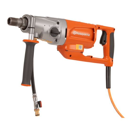
5 Product overview for repair and servicing 5.1 Product overview 1. Drill spindle 2. Front handle 3. Gear selector 4. Carbon brush cover 5. Power switch 6. Rear handle 7. PRCD (Portable Residual Current Device) 1332 - 001 - 04.03.2021 Product overview for repair and servicing - 9... -
Page 10: Repair And Servicing
6 Repair and servicing 6.1 To clean and examine the product parts 3. Remove the 2 screws that hold the carbon brush covers. Remove the carbon brush covers. • Clean and examine all parts fully. You find more instructions in the chapter for each part if special tools or procedures are necessary. - Page 11 5. Remove the 4 screws that hold the motor housing. 6. Put 2 flat screwdrivers in the recesses on the gear Remove the motor housing. housing. Carefully loosen the middle cover. Remove the middle cover together with the rotor. CAUTION: Make sure that the O-ring is not damaged.
-
Page 12: To Assemble The Product
To replace the gear oil on page 14 to replace 7. Tap the rotor shaft carefully with a soft head mallet Refer to to loosen it. the gear oil. 1. Put the middle cover with the rotor on the gear housing. - Page 13 4. Install the carbon brush covers with the 2 screws. CAUTION: Make sure that the O-ring is not damaged. 2. Put the motor housing on the middle cover. Align the screw holes in the gear housing with the holes in the motor housing.
-
Page 14: To Replace The Gear Oil
6.4 To replace the gear oil CAUTION: Make sure that the O-ring is not damaged. Replace the gear oil for the first time after 100 hours of operation. After that, the interval is approximately each 300 hours of operation. 3. Remove the middle cover and the motor housing. 1. -
Page 15: Carbon Brushes
6.6 Gear housing 3. Put the middle cover on 2 spacers. Put gear oil on the surface of the bearing seat in the middle cover. Put a new shaft seal in the bearing seat. Push the 6.6.1 To remove the pinion shaft shaft seal into the bearing seat with the shaft seal 1. - Page 16 6.6.2 To install the pinion shaft 6.6.3 To remove the drill spindle 1. Put the pinion shaft into the gear housing. Tap the Note: Replace the shaft seals if the drill spindle is pinion shaft carefully with a soft head mallet to To replace the shaft seals for the drill removed.
- Page 17 4. Remove the parallel key. 5. Remove the snap ring (A) with circlip pliers. Push CAUTION: Make sure that the metal surface the ball bearing (B) off the drill spindle shaft with the does not become damaged. separator puller tool and a mandrel press. Refer to Servicing tools on page 6 .
- Page 18 6.6.4 To replace the shaft sleeves for the drill 3. Put the first shaft sleeve into the sleeve press tool. Servicing tools on page 6 . Push the first Refer to spindle shaft sleeve onto the drill spindle shaft with the 1.
- Page 19 6.6.5 To install the drill spindle 4. Put the gear wheel into the gear housing. 1. Push the ball bearing onto the drill spindle shaft with Servicing tools on page 6 . a mandrel press. Refer to 5. Put the pin of the gear selector into the groove of the gear wheel.
- Page 20 7. Push the drill spindle into the gear housing with the 6.6.6 To replace the shaft seals for the drill spindle mandrel press. 1. Remove the snap ring (A) with circlip pliers. Note: Push the parts together by hand before you put the assembly in the mandrel press.
- Page 21 3. Use a screwdriver to remove the shaft seal (A). 6. Attach the second shaft seal press tool to the . Put a new shaft seal on the mandrel press. Refer to shaft seal press tool. Push the second shaft seal into the seal seat.
- Page 22 8. Install the washer with a groove (A) as the 10. Install the snap ring (A) with circlip pliers. illustration shows. Install the O-rings (B). Install the washer (C). CAUTION: Make sure that the leak hole does not become blocked. 6.6.7 To remove the ball bearing from the gear housing •...
- Page 23 6.6.8 To install the ball bearing in the gear housing 6.6.9 To remove the needle bearings from the middle cover 1. Put the ball bearing into the bearing seat in the gear housing. 1. Put an inner bearing puller into one of the 2 needle Servicing bearings in the middle cover.
- Page 24 6.6.10 To install the needle bearings in the middle 6.6.11 To remove the gear selector cover • Remove the screw (A), the washer (B) and the bracket (C). Remove the gear selector (D) and the 1. Put the 2 needle bearings into the bearing seats in O-ring (E).
- Page 25 6.6.13 To disassemble the pinion shaft 3. Clean and dry all parts. Examine all parts for wear. Replace damaged parts. 1. Attach the pinion shaft to a vise with soft jaws. 6.6.14 To assemble the pinion shaft 1. Put gear oil on all parts before assembly. Make sure to put gear oil on the two sides of the brake discs.
-
Page 26: Rotor
3. Put the pinion shaft into the pinion shaft holder as 6.7.2 To assemble the rotor the illustration shows. 1. Put the first ball bearing in the first bearing press Servicing tools on page 6 . Put the rotor tool. Refer to shaft into the first ball bearing. -
Page 27: Stator
6.8 Stator 4. Remove the 8 screws that hold the rear handle. 6.8.1 To disassemble the stator To replace the 1. Remove the carbon brushes. Refer to carbon brushes on page 15 . 2. Remove the carbon brush holders. 3. Remove the 5 screws that hold the rear handle. 5. - Page 28 7. Remove the 4 screws that hold the electronic 6.8.2 To assemble the stator module. Remove the electronic module. 1. Put the motor housing onto the 4 pins of the press Servicing tools on tool for motor housing. Refer to page 6 .
- Page 29 3. Install the 2 screws and the air disc. 6. Connect the motor connection wires to the terminal Wiring diagram on of the electronic module. Refer to page 35 . Install the rear handle. 4. Install the electronic module with the 4 screws. CAUTION: Make sure that the wires cannot touch the rotor.
- Page 30 8. Install the 8 screws. 9. Install the carbon brushes. Refer to To replace the carbon brushes on page 15 . 30 - Repair and servicing 1332 - 001 - 04.03.2021...
-
Page 31: Function Test
7 Function test 7.1 Gear housing b) The shaft sleeves must be replaced if the diameter of the groove is smaller than 27.85 mm at the wear area (B). 7.1.1 To do a check of the gear housing and gears •... -
Page 32: Stator
7.3 Stator CAUTION: Replace the first gear wheel if the rotor is replaced as a result of a 7.3.1 To do a check of the stator damaged rotor shaft. • Remove the air disc. 3. Examine the rotor surface (C) for damage. If the rotor is not in the center of the motor housing, the rotor surface can be damaged. -
Page 33: Cables
7.4 Cables 5. Push the "TEST" button. The red indicator goes off. 6. Push the "RESET" button again. The red indicator 7.4.1 To do a check of the power switch and power shows that the current is connected. cord 7.4.3 To examine the electrical cables of the PRCD WARNING: Disconnect the power cord from the power outlet. -
Page 34: To Do A Check Of The Electronics
3. Put the test probes at the connection points as the illustrations show. 7.5 To do a check of the electronics 1. Do a visual check for damaged components. 2. Do a soft start of the motor. Refer to the operator's manual. -
Page 35: Diagrams
8 Diagrams 8.1 Wiring diagram Electronic board Switch Motor strand, 265 mm (pos. 185) Motor strand, 290 mm (pos. 180) 1332 - 001 - 04.03.2021 Diagrams - 35... - Page 36 1142168-26 2021-03-04...