Table of Contents
Quick Links
Table of Contents

Related Manuals for Honeywell 854 ATG Series


Summary of Contents for Honeywell 854 ATG Series
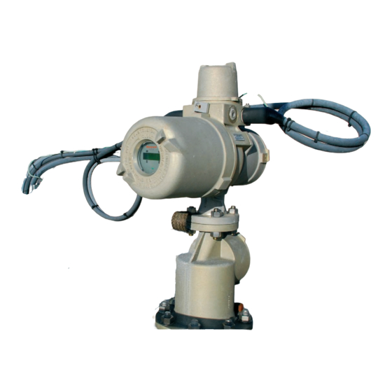
- Page 1 Instruction manual Series 854 ATG level gauge...
- Page 3 September 2013 Part no. 4416.220 Revision 8 Enraf B.V. P.O. Box 812 2600 AV Delft Netherlands Tel. : +31 15 2701 100 : +31 15 2701 111 E-mail : [email protected] Website : www.honeywellenraf.com Instruction manual 854 ATG Page 1...
- Page 4 Copyright 1999 - 2013 Enraf B.V. All rights reserved. Reproduction in any form without the prior consent of Enraf B.V. is not allowed. This manual is for information only. The contents, descriptions and specifications are subject to change without notice. Enraf B.V. accepts no responsibility for any errors that may appear in this manual.
-
Page 5: Preface
Preface Preface This manual is intended for technicians involved with the commissioning and service of the Honeywell Enraf series 854 Advanced Technology Gauge. A description preceding the technical procedures gives the technical information necessary to understand its functioning. It is recommended to read this description prior to performing any of the procedures. -
Page 6: Table Of Contents
Introduction Table of contents Preface ............................... 3 1 Introduction ..............................6 1.1 Principle of measurement ........................7 1.1.1 Level measurement ......................7 1.1.2 Interface between two products .................... 7 1.1.3 Relative density ........................8 1.2 Optional functions ..........................8 1.3 Remote monitoring ..........................8 1.4 Approvals (ATEX / IECEx, FM) ...................... - Page 7 Introduction 5 Maintenance ..............................36 5.1 Preventive maintenance ........................36 5.2 Instrument covers ..........................37 5.3 Drum compartment ........................... 38 5.3.1 Detailed description ......................38 5.3.2 Removing the measuring drum ................... 39 5.3.3 Replacing the drum bearings ....................40 5.4 The electronic compartment......................41 5.4.1 Detailed description ......................
-
Page 8: Introduction
Introduction Introduction The Honeywell Enraf 854 ATG (Advanced Technology Gauge) measures the liquid level and can be programmed to measure two additional interface levels. The 854 ATG has four programmable level alarms, and also provides diagnostic information. This information can be displayed on the internal display, the Portable Enraf Terminal (PET) as well as on remote systems. -
Page 9: Principle Of Measurement
Introduction 1.1 Principle of measurement Figure 1.1 Principle of measurement The principle is based on detection of variations in the buoyancy of a displacer. The displacer is suspended from a strong, flexible measuring wire which is stored on a precisely grooved measuring drum. The shaft of the drum is connected to the stepper motor via a magnetic coupling. -
Page 10: Relative Density
CPI panel indicator. Approvals (ATEX / IECEx, FM) The Honeywell Enraf 854 Advanced Technology Gauges are certified by official testing institutes as KEMA (ATEX) and Factory Mutual to be explosion proof (suitable for zone 0). The gauges are also approved and certified by Weights and Measures (W&M) or Custom and Excise authorities for legal use and custody transfer. -
Page 11: Safety
The 854 ATG is designed to measure the liquid level in storage tanks. The instrument is suitable for flammable liquids (refer to the explosion proof certification data below). For other applications contact Honeywell Enraf. 2.1 Safety aspects of the 854 Advanced Technology Gauge Warning Do not use the instrument for anything else than its intended purpose. -
Page 12: Personal Safety
Safety 2.2 Personal safety Safe execution of the procedures in this manual requires technical experience in handling tools, and knowledge of safety regulations in handling electrical installation in hazardous environments. The sequence of steps in a procedure may also be important from the point of view of personal safety and prevention of damage;... -
Page 13: Commissioning
Commissioning Commissioning Caution Keep screw thread from the compartment covers free from dirt. Grease them lightly with an acid-free grease before closing the instrument. When closing, turn the covers counter-clockwise until the thread clicks into place, then turn clockwise. 3.1 Checks before starting the commissioning Examine the mechanical and electrical installation after the 854 ATG is installed on the tank. -
Page 14: Installation Of Measuring Drum And Displacer
3.2 Installation of measuring drum and displacer 3.2.1 Tools It is recommended to use an 847 PET (Portable Enraf Terminal) to load the different parameters. A tool set for commissioning and maintenance is available from Honeywell Enraf (see figure 3.1). Item Description... -
Page 15: Installation Of Displacer
Use screwdriver for Allen key screws M4 (item 8 of the Honeywell Enraf tool set). • Fix the Allen key screw of the transport bracket. • Check the span wire. It should always be under tension while both ends are correctly positioned in the levers of the motor block and force transducer. -
Page 16: Programming (Configuring) The Gauge
The 847 PET is intrinsically safe and waterproof (IP65) and consists of a full ASCII membrane keyboard and an LCD display (refer to figure 3.5). Alternatively, the Honeywell Enraf service tool Engauge can be used to configure the instrument. The Engauge program runs on a PC under Windows®. - Page 17 Commissioning Protection level 1 Access to items which are not directly measurement related, such as high level alarm (HA), tank identifier (TI), etc. is protected by password 1 (W1). It is possible to modify these data only after entering the correct level 1 password W1=XXXXXX, where XXXXXX is the level 1 password.
-
Page 18: Apply Power To The 854 Atg
Commissioning How to program? When the 847 PET is plugged into the 854 ATG and the instrument is powered, the PET can be switched on. By operating the keyboard, items can be requested and settings can be changed. For example: Item (+ setting) Description (typing in on PET keyboard) -
Page 19: Selecting Dimension And Decimal Separator
Commissioning 3.3.3 Selecting dimension and decimal separator When one of the dimension items are changed, all items with related formats have to be changed and the values must be converted to the new dimension. The same applies for the decimal separator. Note: When the 854 ATG is equipped with an XPU-2 board (can be recognised by requesting the software version item SV reads: XPU ... -
Page 20: Tank And Gauge Data
Commissioning 3.3.4 Tank and gauge data Refer to figure 3.7 for the tank related data. Figure 3.7 Tank related level items Page 18... - Page 21 TA= Transmission address Two digits. The transmission address identifies the gauge on the Honeywell Enraf 2-wire field bus. Each gauge must have a unique address, and hence TA must be programmed differently. When connected to an 858 CIU, please note that the 858 CIU has three...
-
Page 22: Alarm Settings
Exit protection level. 3.3.5 Alarm settings Refer to figure 3.7. The high level alarm (HA) and low level alarm (LA) conditions are transmitted to the host via the 2-wire Honeywell Enraf field bus (or optional RS-channel). Item Name Description Protection level 2 Enter protection level 2 (default level 2 password: ENRAF2). -
Page 23: Ullage Readout
The ullage value is also transmitted to the host via the 2-wire Honeywell Enraf field bus (or optional RS-channel). The ullage, or outage, measurement is referred to a ‘zero’ point at the tank top (upper reference point). -
Page 24: Display Control And Password Protection
Commissioning 3.3.7 Display control and password protection Item Name Description Protection level 2 Enter protection level 2 (default password: ENRAF2) DF= Display format One character. Selects the data which will be shown on the XPU display (refer to Appendix D for a detailed overview). level and temperature level average gas temperature... -
Page 25: Level Calibration
A tank top reference stop is a mechanical device that can hold the displacer at a reproducible position when the displacer is pulled up. This device is placed above the motor limit switch high position. An Honeywell Enraf tank adapter can be provided with such a facility. -
Page 26: Level Calibration Using The Top Of Ball Valve
Commissioning 3.4.3 Level calibration using the top of ball valve If level dipping is not possible, the 854 ATG can be calibrated using the top of a ball valve as reference point. Proceed as follows: Item Name Description Protection level 2 Enter protection level 2 password Calibrate The displacer will be raised until it stops against the flange of the level... -
Page 27: Interface Measurement
Commissioning 3.4.4 Interface measurement Interface 3 (I3) is used as product / water interface measurement (with interface 2 (I2) another interface can be measured). The set point S3 has to be set to such a value that half of the displacer volume is immersed in the water and the other half of the displacer volume is immersed in the product. -
Page 28: Operation
Operation Operation 4.1 Display The 854 ATG has an LCD display consisting of 2 rows of 16 characters each. On the display, one of several formats will appear, depending on the status of the XPU(-2). Immediately after power on the display is blank. Once the power is stable for 20 seconds, the display will show its initializing message. -
Page 29: Xpu Display
Operation 4.1.1 XPU display Display contrast For best readability the viewing angle can be adjusted, using a small potentiometer on the XPU board, on the bottom left (refer to figure). Normally, it is adjusted in the factory for viewing horizontally. Repeatability test If the test magnet (item 7 of the tool kit) is hold for approximately 5 seconds in front of the rectangle block below the display, a repeatability test is performed. - Page 30 Operation Function Additional display and function of other switches switch L Display configuration R display test (blank test / dark test) U display contrast up D display contrast down Display format toggle (formats A - K) U previous display format D next display format NOVRAM item view (all items) R fast forward...
-
Page 31: Repeatability Test
Operation 4.2 Repeatability test With the repeatability test the displacer is raised for approximately 75 mm (3”) and then returns to the product surface. During the test, the level dimension and level type on the display are replaced by exclamation marks (!!! !!!) and the status field (I1) changes to TG. -
Page 32: Freeze And Block Commands
Operation 4.4 Freeze and block commands Both the freeze (FR) and block (BL) commands stops the displacer at the current position. With the freeze command, the displacer remains in its position even when the level reaches the displacer position. Hence, the level can not be followed and the high and high high level alarms can not be generated. The block command stops the displacer, and depending on how the block mode (item BM) is set, the displacer will move up with an increasing level, or the block is cancelled when the level reaches the displacer position. -
Page 33: Interface Measurement
Operation 4.6 Interface measurement The 854 ATG can measure three different interfaces. Interface 1 (I1) is normally used to measure the product level. Interface 3 (I3) can be used to measure the product / water interface. Interface 2 (I2) is a setting for a special measurement (i.e. -
Page 34: Servo Auto Test
Operation 4.8 Servo Auto Test The Servo Auto Test (SAT hereafter) is an automatic safety related function meant to reduce the small risk of tank overfill caused by a failing servo gauge. Immediate after the gauge detects that tank loading has finished a SAT is executed to rule out (or detect) that the gauge is unable to measure the product level due to some failure (e.g. - Page 35 Operation The behaviour of the function responsible for the level movement detection part of the SAT can be influenced by means of 2 configuration parameters. Item Name Description SAT level movement sample interval The movement detector samples the level in the tank at regular intervals.
-
Page 36: Verify Level Calibration
Operation 4.9 Verify level calibration 4.9.1 Verify level calibration against a tank top reference stop When a tank adapter with a tank top reference stop is installed, the level calibration of the 854 ATG can be checked. Proceed as follows: Item Name Description... -
Page 37: Data Items And Operational Commands
Operation 4.10 Data items and operational commands Below a summary of data items, error codes and operational commands. Data items: Item Description Measured data Compensated servo innage*) Servo innage Servo ullage Servo status request Control data Average measured frequency Maximum unbalanced weight Minimum unbalanced weight Average measured weight Frequency request... -
Page 38: Maintenance
Maintenance Maintenance 5.1 Preventive maintenance Whether maintenance is needed can be checked with the following tests: Repeatability test (refer to section 4.2). If repeatability deteriorates (more than 1 mm) the drum bearings should be replaced (refer to section 5.3.3). Balance test The measuring drum unbalance can be measured by the following procedure: Item Name... -
Page 39: Instrument Covers
The 854 ATG is an explosion proof instrument with intrinsically safe output/input circuits. Modification to the instrument may only be carried out by trained personnel which is authorized by Honeywell Enraf. Failure to adhere to this will invalidate the approval certificate. -
Page 40: Drum Compartment
Maintenance 5.3 Drum compartment 5.3.1 Detailed description Figure 5.1 shows the cross-section of the drum compartment of the medium pressure version and identifies the components. Figure 5.2 shows the chemical and high pressure version. The drum shaft, mounted in the drum with a tolerance ring, is inserted into the magnet cap. Two carbon PTFE bearings in the drum shaft bushing support the drum shaft. -
Page 41: Removing The Measuring Drum
Maintenance 5.3.2 Removing the measuring drum Removing the drum from the housing requires no tools. Keep the drum, the outer magnet and the outside of the magnet cap thoroughly clean. To remove the drum proceed as follows: • Issue the CA (calibrate) command to raise the displacer •... -
Page 42: Replacing The Drum Bearings
Maintenance 5.3.3 Replacing the drum bearings • Open the drum cover. • Take out the drum shaft bushing. • Replace the bearings, refer to figure below • Install the bushing. • Install drum and displacer. • Close the cover. Figure 5.3 Replacing the drum shaft bearings Caution Do not grease the carbon PTFE bearings. -
Page 43: The Electronic Compartment
Maintenance 5.4 The electronic compartment 5.4.1 Detailed description The electronic part of the 854 ATG requires no special maintenance. However, a detailed description of the combination of the several parts is given in order to help you in case of software-updates or system enhancements. -
Page 44: Dismantling The Electronic Compartment
Repair of the 854 printed circuit boards Field repair of the electronic boards is not advised. The components that can be replaced in the field are EPROMs and NOVRAM, see section 5.4.3 for updating software versions. Consult the service department of Honeywell Enraf. Page 42... -
Page 45: Replacing Software
When the gauge is powered, issue the IN command by the PET 3 times in sequence. After the first command, use the “↑” key and “enter” key. No other command may interfere in this sequence. Note: To prevent other commands in the initialization sequence, the Honeywell Enraf field bus lines may, temporary, be disconnected. Instruction manual 854 ATG... -
Page 46: Calibrating Force Transducer
Maintenance 5.5 Calibrating force transducer After mounting a new force transducer or another motor-block the force transducer must be calibrated. The frequency of the force transducer must be calibrated with help of a set of accurate test weights of 25 g, 75 g, 150 g and 225 g, all ±0.1 g. Check the mounting of the 854 ATG whether it is stable and horizontal. -
Page 47: Synchronizing The Reference Encoder
Maintenance Do not yet reprogram this value in the gauge. Reprogram all values after completion of all the four calibration measurements. Repeat this calibration from item BT for the other 3 test weight combinations: • for F1 with: (25+75 g), •... -
Page 48: Trouble Shooting
Trouble shooting Trouble shooting The 854 ATG is an instrument with self diagnostics. Detected errors will be shown as status information on the display (refer to Appendix D), or can be requested as items by the PET. The following items contain the error codes of the processor boards: Error XPU(-2) request (communication processor unit) Error SPU request (servo processor unit) These items contain an error code of the last error condition. -
Page 49: Xpu Error Code (Item Ep)
Some XPU error codes of item EP are listed below, with suggestions for solving the problem. For a complete overview, refer to “Item documentation for Honeywell Enraf series 854 ATG” and in the item help of the service tool Engauge. -
Page 50: Spu Status Request (Item Qs)
Trouble shooting 6.4 SPU status request (item QS) The servo status request (item QS) consists of four bytes. Bytes 0, 1 and 2 are bit coded with information about the level alarms, operational mode and general status. Byte 3 is an ASCII character that indicates the active operational command. -
Page 51: Appendix A Article And Part Numbers
Appendix Appendix A Article and part numbers Description Part no. drum with 27 m stainless steel wire + shaft and tolerance ring S0854962 drum with 37 m stainless steel wire + shaft and tolerance ring S0854963 drum with 150 m stainless steel wire S0854325 set screw + ring (6 pc. - Page 52 Appendix Description Part no. pull wire S0854151 force transducer S0854485 electronic compartment cover + window S0854952 anti seize grease S4000015 motor board S0894601 motor assembly S0854957 ball bearing (set of 2 pc.) S2100418 IR connector (chassis part) S0854380 displacer, material PTFE (25% carbon) 25 mm S0815360 45 mm...
- Page 53 Appendix Instruction manual 854 ATG Page 51...
-
Page 54: Appendix B Additional Information On Displacers
Appendix Appendix B Additional information on displacers Displacer type Part number Displacer area (DA) Displacer volume (DV) Displacer weight (DW) Carbon filled PTFE ø 25 mm S0815360 +.10000000E+02 +.10500000E+03 +.22300000E+03 ø 45 mm S0815343 +.16000000E+02 +.10500000E+03 +.22300000E+03 ø 90 mm S0815344 +.64000000E+02 +.10500000E+03... - Page 55 Appendix Instruction manual 854 ATG Page 53...
-
Page 56: Appendix Cascii Table
Appendix Appendix C ASCII table Page 54... -
Page 57: Appendix D Display Formats
Appendix Appendix D Display formats Level and Temperature display (format A) Instruction manual 854 ATG Page 55... - Page 58 Appendix Level display (format B) Average gas temperature display (format C) Page 56...
- Page 59 Appendix Average product temperature display (format D) HIMS density display (format E) Instruction manual 854 ATG Page 57...
- Page 60 Appendix HIMS pressure displays (format F and H) Servo density display (format I) Page 58...
- Page 61 Appendix Analog level output display (format J) Water level display (format K) Instruction manual 854 ATG Page 59...
-
Page 62: Appendix Epcb Layout
Appendix Appendix E PCB layout XPU-2 SPU-II Page 60... -
Page 63: Appendix F Related Documents
Instruction manual 977 Tank Side Indicator Instruction manual 847 Portable Enraf Terminal Instruction manual Engauge service tool Item documentation for Honeywell Enraf series 854 level gauges, 97x SmartRadar and 877 FDI Protocol manual for 854 series level gauges Instruction manual Foundation... -
Page 64: Index
Calibrate ........... 23, 24, 34, 35 Electronic compartment ........42 Carbon PTFE bearings ........38 Encoder disk ............7 Caution ............... 10 Honeywell Enraf field bus........21 CD ............... 27 ENRAF1 .............. 22 CIU ..............19 ENRAF2 ..........16, 17, 19, 22 Commands ........... - Page 65 Index HA ............... 20 Motor block ........13, 41, 42, 45 Hall switches ............27 Motor limit switch high ......... 19 HC ............... 47 position............23 Health ..............10 Motor limit switch low .......... 19 HH ............... 20 Motor shaft ............7 Highway ..............
- Page 66 Index Standard floating point format......17 UN ..........16, 24, 30, 34, 35 Stepper motor ............7 Unlock ......... 16, 24, 30, 34, 35 SV ..............17, 43 Upper reference ..........21 SY ..............32 point ............... 21 System configuration .......... 28 UQ ...............
- Page 68 Honeywell Enraf Delftechpark 39 2628 XJ Delft The Netherlands Tel: +31 (0)15-2701 100 Email: [email protected] 4416220 - Revision 8 September 2013 www.honeywellenraf.com © 2013 Honeywell International Inc.