Table of Contents
DOCUMENT: NBZ0003
INSTRUCTION MANUAL
INSTALLATION – OPERATION - MAINTENANCE
TE Series
Low Voltage
Digital
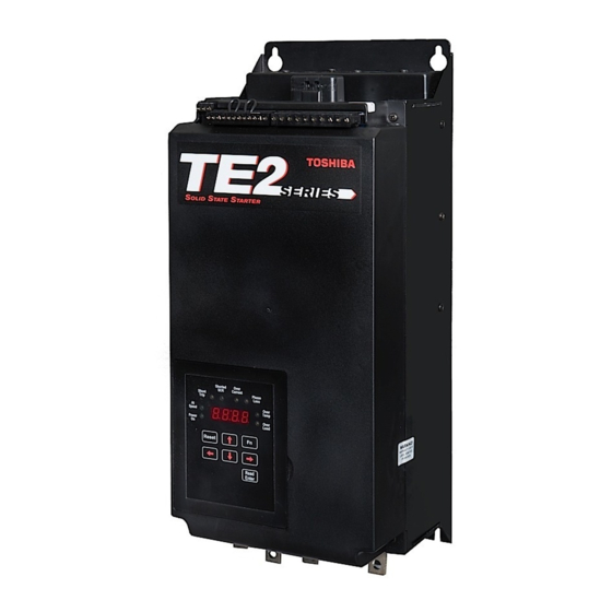
Solid State Soft Starter
18 – 1250A
Issued: 9/12
Firmware Version 4.31
Buy: www.ValinOnline.com | Phone 844-385-3099 | Email: [email protected]
Table of Contents

Related Manuals for Toshiba TE Series


Summary of Contents for Toshiba TE Series
- Page 1 DOCUMENT: NBZ0003 INSTRUCTION MANUAL INSTALLATION – OPERATION - MAINTENANCE TE Series Low Voltage Digital Solid State Soft Starter 18 – 1250A Issued: 9/12 Firmware Version 4.31 Buy: www.ValinOnline.com | Phone 844-385-3099 | Email: [email protected]...
- Page 2 Basic Installation and Operation Guide TE Series Digital Solid State Soft Starters 18 – 1250A Buy: www.ValinOnline.com | Phone 844-385-3099 | Email: [email protected]...
- Page 3 The sales contract contains the entire obligation of Toshiba International Corporation. The warranty contained in the contract between the parties is the sole warranty of Toshiba International Corporation and any statements contained herein do not create new warranties or modify the existing warranty.
- Page 4 Toshiba International Corporation. © Copyright 2012 Toshiba International Corporation. TOSHIBA® is a registered trademark of Toshiba Corporation. All other product or trade references appearing in this manual are registered trademarks of their respective owners.
- Page 5 TE Series Digital Solid State Soft Starters 18 – 1250A Contacting TIC’s Customer Support Center Toshiba International Corporation’s Customer Support Center can be contacted to obtain help in resolving any system problem that you may experience or to provide application information.
- Page 6 Basic Installation and Operation Guide TE Series Digital Solid State Soft Starters 18 – 1250A General Safety Information DO NOT attempt to install, operate, maintain, or dispose of this equipment until you have read and understood all of the product safety information and directions that are contained in this manual.
- Page 7 Basic Installation and Operation Guide TE Series Digital Solid State Soft Starters 18 – 1250A Equipment Warning Labels DO NOT attempt to install, operate, perform maintenance, or dispose of this equipment, until you have read and understood all of the product labels, and user directions, that are contained in this manual.
- Page 8 ONLY. When modifications are required contact your Toshiba Customer Support Center. • Inspections may be required after moving the equipment. • Contact your Toshiba Customer Support Center to report discrepancies or for assistance if required. Handling and Storage • Use proper lifting techniques when moving the breaker; including properly sizing up the load, getting assistance, and using a forklift if required.
-
Page 9: Table Of Contents
Basic Installation and Operation Guide TE Series Digital Solid State Soft Starters 18 – 1250A Table of Contents Page Chapter 1: Introduction General Description …………………… Sizes and Ratings ……………………… Chapter 2 - Installation Receiving and Unpacking …………….. Choosing a Location …………………... -
Page 10: Chapter 1: Introduction
LEDs. Starting torque, ramp time, current limit, dual ramp, and Decel control are standard features on the TE Series. By simply adjusting the unit’s starting torque, ramp time and current limit... - Page 11 Basic Installation and Operation Guide TE Series Digital Solid State Soft Starters 18 – 1250A 1.1.2 Advanced Motor Protection Features A sophisticated Thermal Model of the motor operation is created in the Thermal Model Electronic microprocessor to accurately track all starting, stopping and running conditions Overload Protection thus, providing maximum motor protection.
- Page 12 Basic Installation and Operation Guide TE Series Digital Solid State Soft Starters 18 – 1250A 1.1.3 Design Specifications Type of Load: Three phase AC induction motors. AC Supply Voltage: Universal, 208 - 600VAC ±10%, 50/60 Hz. Power Ratings: 18 - 1250 Amps, 7.5 - 1000 HP @ 460V.
-
Page 13: Sizes And Ratings
Model above the nameplate current rating. If using this Service Number Factor, the TE Series starter must be sized for the total amps Min.- Max. used. For proper selection of the TE Series starter when using SF continuously, multiply the nameplate FLA by the stated... -
Page 14: Chapter 2 - Installation
HP and current rating with which it is to be used. Choosing a Location Proper location of the TE Series is necessary to achieve specified performance and normal operational lifetime. The TE Series should always be installed in an area where the following conditions exist: ... -
Page 15: Service Warning
Basic Installation and Operation Guide TE Series Digital Solid State Soft Starters 18 – 1250A SERVICE WARNING! Do not service equipment with voltage applied! The unit can be the source of fatal electrical shocks! To avoid shock hazard, disconnect main power and control power before working on the unit. Warning labels must be attached to terminals, enclosure and control panel to meet local codes. -
Page 16: Power Terminations
Basic Installation and Operation Guide TE Series Digital Solid State Soft Starters 18 – 1250A WARNING! Remove all sources of power before cleaning the unit. In dirty or contaminated atmospheres, the unit should be cleaned on a regular basis to ensure proper cooling. Do not use any chemicals to clean the unit. - Page 17 Basic Installation and Operation Guide TE Series Digital Solid State Soft Starters 18 – 1250A 2.6 Power Connections (cont.) TE-150 ~ TE-160 Line Load 0.38" (9.64 mm) 1.52" 2.81" (38.58 mm) (71.32 mm) 1.54" (39.09 mm) 0.60" (15.23 mm)
-
Page 18: Remote Keypad Mounting
Basic Installation and Operation Guide TE Series Digital Solid State Soft Starters 18 – 1250A 2.6.1 Power Terminals: Connection points are bus tabs with pre-drilled holes (see below). Use appropriate compression or mechanical lugs for termination to these bus tabs. -
Page 19: Dimensions
Basic Installation and Operation Guide TE Series Digital Solid State Soft Starters 18 – 1250A Dimensions (consult price catalog for enclosed units) Table 2.8: TE Dimensions and Weights Overall Mounting Weight Enclosure Model Number Inches Inches Inches Inches Inches Inches... -
Page 20: Chapter 3 - Motor Overload Protection
Note: All TE Series starters are shipped from the factory with F001 set to a default value of 0000. If F001 is left at the factory default, the unit will not operate. If the user attempts to start the TE Series without entering the motor nameplate FLA, the starter will Fault and the display will read “nFLA”... - Page 21 Series is wired downstream from an existing starter, this feature can be disabled to prevent conflicts with external overload protection devices. When the TE Series is controlling multiple motors, the built-in Overload protection must be disabled and individual thermal overload relays must be installed on the motor leads going to each motor (see appendix 4 for additional details).
-
Page 22: Nema Class Trip Curves
Overload Protection During Bypass When an integral Bypass Contactor is used to shunt power around the SCRs in the TE Series (as in the TE…-BP version), overload protection is maintained as long as the TE Series is directly controlling the contactor. No additional Overload Relay is necessary for normal operation. - Page 23 Basic Installation and Operation Guide TE Series Digital Solid State Soft Starters 18 – 1250A 3.2.3 Running Overload Curve During the Run mode, Overload trip curves are selectable from NEMA Class 5, 10, 15, 20, 25, and 30. Program the appropriate curve according to the characteristics of your motor and load.
-
Page 24: Chapter 4 - Connections
Power Factor Correction Capacitors Power factor correction capacitors can be connected to motors controlled Figure 4.1: by TE Series starters; however they must be off-line during ramping. TE Power Connections Connect PFC capacitors to the Line side of the starter with a separate capacitor control contactor. -
Page 25: Control Connections
TE Series Digital Solid State Soft Starters 18 – 1250A 4.1.4 Testing The TE Series can be tested with a load smaller than the motor it was originally selected to control, however additional steps must be taken to avoid tripping on Phase Current Loss. See section 5.6.8.a under “Phase Loss Protection”... - Page 26 120VAC Separate AC Control Power supply is required to power the electronics Supply of the TE Series starter. 120VAC is standard; order 240VAC (optional) if necessary for your line power supply configuration. The control voltage A1 A2 must be connected to terminals marked A1 and A2 of TB-2 as shown in figure 4.2.1 (these are also Terminal No.’s 21 and 22).
- Page 27 (voltage free) maintained contact closure between terminals 1 and 3 as shown in Figure 4.2.3. When this contact is closed, the TE Series starter will start and run. When it is opened, it is the same as a Stop command.
- Page 28 OPTO Closing a dry (voltage free) contact between TB1, terminals 6 and 7 will enable Ramp 2, and the TE Series starter will respond to the settings for Ramp 2 in F015 - F018. If no contact closure is present, the TE Series starter defaults to the Ramp 1 parameters (F011 –...
- Page 29 Basic Installation and Operation Guide TE Series Digital Solid State Soft Starters 18 – 1250A 4.2.6 PTC Thermistor Input The TE Series starter is provided with input terminals for connecting a RAMP2 OPTO PTC (Positive Temperature Coefficient) Thermistor that may be imbedded in the motor.
- Page 30 4.2.8 Output (Auxiliary) Relay Contacts Three programmable auxiliary relays are on TB2. The TE Series starter comes with three programmable dry relay output contacts. Outputs 1 and Internal Connections 2 are Form C (SPDT), with a Common, N.O. and N.C. Output 3 is a Form A, (SPST), N.O.
- Page 31 No field wiring is necessary to these terminals if this feature is not used. For all other styles of TE Series, the At-Speed signaling can be programmed into any of the three Output relays (section 4.2.8 and Table 5.6.9).
-
Page 32: Chapter 5 - Programming
MUST be set by the user is motor FLA (F001). Digital Interface The TE Series Soft Starter includes a digital keypad with eight LEDs, seven command keys, and an LED display with four alphanumeric digits. Table 5.2: TE Series Display Features Reset Clears the Trip indication and releases the Trip Relay. -
Page 33: Display Modes
Basic Installation and Operation Guide TE Series Digital Solid State Soft Starters 18 – 1250A Display Modes There are three modes of display: The Status Display Mode, the Program Mode, and the Fault Mode. 5.3.1 Status Display Mode (Default Display) The Status Display Mode displays seven “screens”... -
Page 34: Program Mode
Basic Installation and Operation Guide TE Series Digital Solid State Soft Starters 18 – 1250A Program Mode The starter must be OFF in order to enter the Program Mode. Use the Program Mode to view or change Function (Fn) settings. To enter the Program Mode, press the [Fn] key once from the Status Screen described in 5.3.1 above. - Page 35 5.4.2 Enabling Password Protection / Parameter Lock TE Series starter is shipped with the password protection disabled (F070 = 0). If it becomes necessary to prevent parameters from being changed inadvertently, set the password in function F070. See Appendix 3 for details.
- Page 36 Basic Installation and Operation Guide TE Series Digital Solid State Soft Starters 18 – 1250A 5.4.3.a Changing a Value by Increments Although it may be easier to shift the cursor position, it is also possible to increase or decrease values by pressing the UP or DOWN arrow keys successively.
-
Page 37: 5.4.5 Fault Mode
Basic Installation and Operation Guide TE Series Digital Solid State Soft Starters 18 – 1250A 5.4.5 Fault Mode The Fault Mode Display provides information to the operator when a fault occurs and allows the operator to review fault history. Refer to Section 7 for details. - Page 38 5.4.5.c Automatic Reset The TE Series starter provides for automatic reset on certain non- critical faults and Overload. For non-critical fault resets, see section 5.6.8 for program details of F052 and F053. For automatic Overload reset, see section 3.1 and 5.6.1 for programming details.
-
Page 39: The Te Function List
Basic Installation and Operation Guide TE Series Digital Solid State Soft Starters 18 – 1250A The TE Function List 5.5.1 Motor FLA, Service Factor and Overload Protection Functions Setting Factory Fn # Group Function Description Adjustment / Display Range Section... - Page 40 Basic Installation and Operation Guide TE Series Digital Solid State Soft Starters 18 – 1250A 5.5.3 Jog Mode Functions Setting Factory Fn # Group Function Description Adjustment / Display Range Section Increments Setting F019 Voltage Jog 5 – 100% Line Voltage 5.6.3...
- Page 41 Basic Installation and Operation Guide TE Series Digital Solid State Soft Starters 18 – 1250A 5.5.7 Current and Ground Fault Protection Features Setting Factory Fn # Group Function Description Adjustment / Display Range Section Increments Setting 0 = Disabled, or...
- Page 42 Basic Installation and Operation Guide TE Series Digital Solid State Soft Starters 18 – 1250A 5.5.9 Output Relay Programming Features Setting Factory Fn # Group Function Description Adjustment / Display Range Section Increments Setting Operation # 1 – 26: see...
- Page 43 Basic Installation and Operation Guide TE Series Digital Solid State Soft Starters 18 – 1250A 5.5.11 System Settings Setting Factory Fn # Group Function Description Adjustment / Display Range Section Increments Setting 5.6.11 0 – 999 Parameter Lock (displays F070...
- Page 44 Basic Installation and Operation Guide TE Series Digital Solid State Soft Starters 18 – 1250A 5.5.12 Fault History and Run Time Setting Factory Fn # Group Function Description Adjustment / Display Range Section Increments Setting 0 = No fault history, or...
-
Page 45: Function Descriptions
TE Series Digital Solid State Soft Starters 18 – 1250A Function Descriptions Your TE Series starter is set at the factory with typical default settings that perform well in most applications. Following are detailed descriptions of each Function and the factory default settings. - Page 46 If 2-wire control is used, the unit will restart immediately. When set to 2 = Disabled Overload, the TE Series will not trip on Motor Thermal Overload. This is provided for applications where either an external Overload Relay or Motor Protection Relay is used, or where multiple motors are connected and each one requires having an individual Overload Relay.
-
Page 47: Starting Mode
5.6.2 Starting Mode The TE Series is capable of several different starting modes, but is set from the factory for the most common applications. A second ramp profile is available for use should it be required. Unless wired to do so, the TE Series defaults to Ramp 1. - Page 48 Factory Setting = 350% Range = 200 - 600% Sets the maximum motor current that the TE Series starter will allow during Ramp 1. This limit applies to both voltage and current ramping. Current will be limited to this setting until either the motor reaches full speed or the over load protection feature trips (F003).
- Page 49 Factory Setting = 350% Range = 200 - 600% Sets the maximum motor current that the TE Series starter will allow during ramp 2. (This limit applies to both voltage and current-type ramping.) The current will be limited to this setting until either the motor reaches full speed or the over load protection feature trips (F003).
- Page 50 TB1 Terminals 6 and 7. If this input is left open, the TE Series will ignore all Jog settings. Engaging the Jog feature along with the Start / Run Command provides an output from the SCRs, but will not continue ramping to full acceleration.
-
Page 51: 3/4 Jog Mode / Kick Start Mode
Basic Installation and Operation Guide TE Series Digital Solid State Soft Starters 18 – 1250A 5.6.4 Kick Start Mode Kick Start applies a pulse of voltage to the motor producing a momentary Kick Start Normal Ramp “kick” of high torque to break the motor load free from high friction or Voltage Setting frozen components. -
Page 52: Pump-Flex Decel Mode
Decel Mode (F025 through F028) Pump-Flex deceleration is a feature of the TE Series Soft Starter that slowly decreases the applied voltage to the motor when a stop command is given, resulting in a gentle decrease in motor torque. Deceleration provides a way to extend the stopping time so that abrupt stopping does not occur. -
Page 53: Restart Delay
LONGER to stop than if it were simply turned off. 5.6.6 Restart Delay The TE Series can be programmed to delay restarting upon restoration of line power after an outage. This allows multiple units to be programmed to restart at staggered times in an effort to avoid causing additional problems with the power supply system. -
Page 54: Current And Ground Fault Protection
Basic Installation and Operation Guide TE Series Digital Solid State Soft Starters 18 – 1250A 5.6.7 Current and Ground Fault Protection Features F040 – F050 set extended protection features that may be used in the TE Series starter. Percentages shown are all based automatically upon the Motor FLA setting from F001 except Ground Fault, F046. - Page 55 Basic Installation and Operation Guide TE Series Digital Solid State Soft Starters 18 – 1250A of any phase drops below F044 for more than 2 seconds, the starter will trip. 5.6.7.a Ground Fault F046 – F047provides Ground Fault protection for equipment only (a.k.a.
-
Page 56: Lockouts, Reset & Internal Protection
Basic Installation and Operation Guide TE Series Digital Solid State Soft Starters 18 – 1250A 5.6.8 Lockouts, Reset and Internal Protection Features F048 – F050provide lockout protection for motors and equipment that may have potentially damaging consequences from premature restart or with limited duty cycles. - Page 57 Basic Installation and Operation Guide TE Series Digital Solid State Soft Starters 18 – 1250A F050 = Minimum Time Between Starts Lockout Factory Setting = 0 (Disabled) Range = 1 - 60 minutes, or 0 (Disabled) When F050 is set to 1 through 60, the motor cannot be restarted within the time specified after the first start.
- Page 58 TE Series Digital Solid State Soft Starters 18 – 1250A Phase Rotation Protection: The TE Series is set up to monitor an expected phase rotation and will trip if this changes. Control of this feature is divided into two categories: On-Off and Expected Sequence.
- Page 59 TE Series Digital Solid State Soft Starters 18 – 1250A Shunt Trip: Shunt Trip is a feature that will cause an immediate Trip if the TE Series detects current flowing through any phase (or all) while the TE is in the Off state.
- Page 60 Basic Installation and Operation Guide TE Series Digital Solid State Soft Starters 18 – 1250A 5.6.8.a (continued) Function 51: Internal Protection Features Fault Default Protection Decimal Display Description Function Value Code Setting Phase Rotation protection. Phase Phase rotation must match selection in Bit #2...
- Page 61 Factory Setting = 0 (Disabled) Range = 1 - 10 Attempts, or 0 (Disabled) If F053 = 1 through 10, the TE Series will attempt to restart if the Start Command is present for this number of times. If F053 is set to “Zero”, the starter will not attempt to reset automatically.
- Page 62 Basic Installation and Operation Guide TE Series Digital Solid State Soft Starters 18 – 1250A 5.6.8.c Timer Value Readouts for Protection Features F054 – F059 provide display of timer or register values for information only. The user cannot alter them. Upon power loss and restoration, these values are updated for time elapsed.
-
Page 63: Output Relays
Output Relays There are three programmable relays (rated 240VAC, 5A, 1200 VA) in the TE Series. They can be programmed for change of state indication for any one of the 25 conditions identified in the following chart. F060 = Aux Relay 1: Form C (SPDT) -
Page 64: Communications
TE Series Digital Solid State Soft Starters 18 – 1250A 5.6.10 Communications The TE Series starter is shipped from the factory ready to accept RS-485 Serial Communications using Modbus RTU protocol. F065 – F067 are used to set the communications parameters in the starter for use by the adaptor module. -
Page 65: System Settings
Basic Installation and Operation Guide TE Series Digital Solid State Soft Starters 18 – 1250A 5.6.11 System Settings The following functions set operator interface controls and unit programming. Also contained here are the Clock settings used for history functions. Change the Clock settings if accurate time values are important. - Page 66 Read Only. Reserved for Factory Use F074 = CT Ratio: Read Only. This is the primary value of the TE Series internal Current Transformers (CTs) for use in determining the GF trip settings (F046). CTs cannot be used for external metering.
-
Page 67: Fault History And Statistical Data
Basic Installation and Operation Guide TE Series Digital Solid State Soft Starters 18 – 1250A 5.6.12 Fault History and Statistical Data F085 – F097 contain the Fault History and Statistical data for the Run Mode. 5.6.12.a Fault History Fault codes for each of the three latest events are stored with time and date stamps;... - Page 68 Basic Installation and Operation Guide TE Series Digital Solid State Soft Starters 18 – 1250A 5.6.12.b Statistical Data F094 - F097 display information from the Run Time / Elapsed Time meter and Run-Cycle counter. Run Time includes Accel, Run, Decel, and Jog operations.
-
Page 69: Chapter 6 - Start-Up
TE Series Digital Solid State Soft Starters 18 – 1250A Chapter 6 - Start-up Basic Startup Your new TE Series Soft Starter is factory preset for a wide variety of applications and often can be used with minimal adjustment. 6.1.1 Three Step Process 1. -
Page 70: Start-Up Check List
Basic Installation and Operation Guide TE Series Digital Solid State Soft Starters 18 – 1250A Start-up Check List Supply voltage matches the rated supply voltage of the unit. Horsepower and current ratings of the motor and starter have the same rating or the starter has a higher rating. -
Page 71: Testing With A Smaller Motor
Testing with a smaller motor To test the TE Series starter in combination with a motor that draws less than 20% of the starters Max Amp rating, the Phase Current Loss (Running) protection must be disabled as per instructions in section 5.6.8.a. - Page 72 Basic Installation and Operation Guide TE Series Digital Solid State Soft Starters 18 – 1250A Fault Number Fault Display Code used in Code Display Message Description History, Readout Indicator F085, F088 and F091 No Full Load Amps entered into F001...
-
Page 73: Fault Explanation
Basic Installation and Operation Guide TE Series Digital Solid State Soft Starters 18 – 1250A Fault Explanation - Probable Cause - Solution Fault Fault # or Fn List Code / Code Explanation: Probable Cause: Solution Description Motor nameplate Full Load Amps (FLA) was not entered by the None user. -
Page 74: Appendix 1: Ramp Profile Details
TE Series Digital Solid State Soft Starters 18 – 1250A Appendix 1 - Ramp Profile Details The TE Series offers four different types of starting ramp profiles. Simply select the one that best matches your motor / load requirements. In addition, two separate ramps are available that can be selected via contact closure (see section 4.2.5.a), and each one can be set up for any... - Page 75 This feature can be used with or without the Maximum Current Limit setting. To achieve Torque Ramping with the TE Series, set the Ramp Profile (F010) to 0002 or 0004 (Current Ramp), and the Maximum Current Limit setting (F014) to the desired level. Initial Torque setting comes from the Initial Current function F012.
- Page 76 Voltage Ramp (F010=1) and if the motor does not reach full speed while in current limit mode. 2. An “Anti-Oscillation” circuit built-in to the TE Series will shorten the Ramp Time if the motor reaches full speed before end of ramp.
-
Page 77: Appendix 2: Pump-Flex Decel Mode Application Considerations
Check Valve. By this time there is very little energy left in the moving fluid and the Shock Wave is avoided. When the output voltage to Check Valve the motor is low enough to no longer be needed, the TE Series will end Closes Slowly ... - Page 78 Basic Installation and Operation Guide TE Series Digital Solid State Soft Starters 18 – 1250A Setup and Use Pump systems vary greatly. To accommodate this, the Pump- Flex Decel control feature is designed to provide complete flexibility in how the deceleration process takes place by using the following settings.
- Page 79 Basic Installation and Operation Guide TE Series Digital Solid State Soft Starters 18 – 1250A F025 = Begin Decel Level (BDL) Factory Setting = 60% Range = 0 - 100% of line voltage Used to drop voltage to a level where there is a noticeable effect on motor torque during Decel mode.
-
Page 80: Appendix 3: Parameter Lock / User Password Instructions
User Password. Existing passwords are encoded to “hide” them in the display. Caution: DO NOT LOSE YOUR PASSWORD. If the password has been lost or forgotten, contact Toshiba for assistance. 71 | P a g e Buy: www.ValinOnline.com | Phone 844-385-3099 | Email: [email protected]... - Page 81 Basic Installation and Operation Guide TE Series Digital Solid State Soft Starters 18 – 1250A Example: Figure App 3 Enabling Password Protection / Parameter Lock Example: Setting a Password Starting from the Status Display Mode, no previous function number entered, no existing password...
-
Page 82: Appendix 4: External Over Load Relay Application
NC aux contact of the external device so that a fault will still shut down the TE Series and be annunciated on the display. See section 4.7.2.a for more details on using the PTC input. - Page 83 Basic Installation and Operation Guide TE Series Digital Solid State Soft Starters 18 – 1250A TE Bypass Control Terminal Location Diagrams Bypass Control Terminals Bypass Control 18 - 48A Units Terminals with integral 62 - 160A Units with bypass integral bypass Note: Use these terminals only when separate control of the Bypass Contactor is necessary.
- Page 84 TE Series, which begins ramping. When At-Speed status is reached, an internal Bypass Pilot Relay is used to close the Bypass Contactor. While in this mode, the TE Series CPU provides full motor protection, even when the Bypass Contactor closes.
- Page 85 NC auxiliary contact of the external OLR so that a trip will still shut down the TE Series and be annunciated on the display. Multiple OLRs would then be wired in series for the same effect.
- Page 86 (default) is used. If started in Fast, different ramp settings are necessary so Ramp 2 is used. (See section 4.2.5.a for Dual Ramp info.) Either OLR will trip the TE Series, which will display [Ptc] and light the “Overload” LED. 77 | P a g e Buy: www.ValinOnline.com | Phone 844-385-3099 | Email: [email protected]...
-
Page 87: Appendix 5: Soft Starter Settings Record
Basic Installation and Operation Guide TE Series Digital Solid State Soft Starters 18 – 1250A Appendix 5 - Soft Starter Settings Record The following chart may be used to record the changes made to the factory settings. Setting Factory Fn #... - Page 88 Basic Installation and Operation Guide TE Series Digital Solid State Soft Starters 18 – 1250A Appendix 5 (cont.) Soft Starter Settings Record Setting Factory Fn # Group Function Description Adjustment / Display Range Setting Increments Setting 0 = Disabled (coast to stop)
- Page 89 Basic Installation and Operation Guide TE Series Digital Solid State Soft Starters 18 – 1250A Appendix 5 (cont.) Soft Starter Settings Record Setting Factory Fn # Group Function Description Adjustment / Display Range Setting Increments Setting 0 = Disabled, or...
- Page 90 Basic Installation and Operation Guide TE Series Digital Solid State Soft Starters 18 – 1250A Appendix 5 (cont.) Soft Starter Settings Record Setting Factory Fn # Group Function Description Adjustment / Display Range Setting Increments Setting 0 = Disabled F065...
- Page 91 Basic Installation and Operation Guide TE Series Digital Solid State Soft Starters 18 – 1250A Appendix 5 (cont.) Soft Starter Settings Record Setting Factory Fn # Group Function Description Adjustment / Display Range Setting Increments Setting 0 = No fault history, or...