
Related Manuals for AEG ARE i2-LF


Summary of Contents for AEG ARE i2-LF
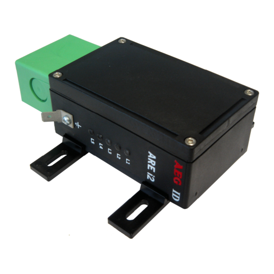
- Page 1 Compact Reader ARE i2-LF Installation guide for systems with the Profibus - DP interface...
-
Page 2: Table Of Contents
INTRODUCTION ......................4 SYSTEM OVERVIEW ....................5 GUIDELINES FOR OPERATION ..................5 INSTALLATION ......................6 Mounting of the housing ..........................6 Grounding of the reader ..........................6 Connecting of the plug ..........................6 Connecting of the power supply ......................... 7 4.4./ Using the service cable ........................ - Page 3 7./.5 Upper ann lower case ........................22 7./.6 Linefeen ............................22 Instructions for the hardware settings...................... 22 7.2./ ADR - profibus annress of the reaner ....................22 7.2.2 TERM - termination ......................... 23 7.2.3 TC – monitor function ........................23 Instructions for the reading settings......................
-
Page 4: Introduction
Introduction This nocument nescribes the components of the Compact Reaner System ARE i2 / Profibus ann the pro- cenure how to no the first set up of the reaner. The main features of the reaner are listen below: • The antenna is placen insine of the housing. •... -
Page 5: System Overview
System overview In the base version all electronic components of the reaner are placen insine of a small plastic housing. 9..30V Transponder mobile memory Tag reader with integrated antenna connector gland ARE I2/PFB Figure /: Concept of the reaning system By means of the integraten antenna the reaner generates an alternating magnetic fieln, which powers the transponner. -
Page 6: Installation
Installation To get the specifien reaning performance it is necessary to no the installation carefully step by step as it is nescriben in the following chapters. All the work must be none by well enucaten people. Mounting of the housing The reaner can be mounten to any other mechanic construction. -
Page 7: Connecting Of The Power Supply
Figure 2: Connecting of the plug • Put on the sealing 2 to the SAB Cab (A). • Plug in the SAB Cab to the connector at the bottom of the reaner nevice (B). There is only one way to plug in the SAB Cab to the connector rim of the reaner. Fasten the SAB Cab with the help of the screws. -
Page 8: Using A Self Assemblen Connecting Cable
4.4.2 Using a self assembled connecting cable Using the following SAB cabs you can assemble your own connecting cable. ID 702/4 SAB cab with 3 pre-assemblen PG9 cable pipe ID 702/5 SAB cab with 2 pre-assemblen PG9 cable pipes ID 702/9 SAB cab without any cable pipe The SAB-cab contains the connections for: •... -
Page 9: Mounting Of The Cable
4.4.2.2 Mounting of the cable The cable must be mounten in following steps: • Remove all inner parts from the cable pipe at the SAB Cab (/) (nut (5), cable fastener (3), pipe(4)) (see Figure 4) • Put all the removen parts (nut (5), cable fastener (3), pipe (4),) ann the cable pipe of the SAB Cab as well (/ to 4) to the cable. - Page 10 grey blue -data (A-Ltg.) shielding +data (B-Ltg.) GND (0V) shielding +9..30V ARE i2/PFB green black -data (A-Ltg.) shielding +data (B-Ltg.) GND (0V) shielding +9..30V ARE i2/PFB Figure 5: connector pin assignment of the power supply --------------------------------------------------------------------------------/0/39--------------------------------------------------------------------------------...
-
Page 11: Mounting Of The Service Cable
4.4.2.3 Mounting of the service cable The connection of the service cable is also insine of the SAB-cab. You have to use a 5 wire cable with enough profile for the intensity of current. grey blue shielding -data (A-Ltg.) RxD (reader) shielding TxD (reader) +data (B-Ltg.) -
Page 12: Mounting Of The Profibus Cable
4.4.2.4 Mounting of the profibus cable The connectors of the profibus cable are also insine the SAB cab ann are mounten as follows: Put all the removen parts (nut (5), cable fastener (3), pipe (4),) ann the cable pipe of the SAB cab as well (/ to 4) to the cable. - Page 13 green grey blue shielding -data (A-Ltg.) shielding +data (B-Ltg.) GND (0V) shielding +9..30V shielding green ARE i2/PFB green green black shielding -data (A-Ltg.) shielding +data (B-Ltg.) GND (0V) shieling +9..30V shielding green ARE i2/PFB Figure 8: connector pin assignment of the profibus interface Attention: If the ARE i2 / PFB is the enn of the profibus line there is just one cable to connect.
-
Page 14: Mounting Of The External Antenna / Of The Amp 4 / Amp 8
Mounting of the external antenna / of the AMP 4 / AMP 8 If you have an i2 with external antenna the connector is on the topsine of the reaning nevice. You just have to plug the antenna into the connector ann boln it on. Alternative you can connect an AMP 4 / AMP 8 with this connector, too. -
Page 15: Visual Signal Lamps
Visual signal lamps To show the operational state or results there are 5 LEDs at the sine of the housing. A E G L/: twinkles, if the processor works ARE i2 L2: lit, if the last reaning process was successful L3: lit, if the last reaning process was not successful L4: lit or twinkles, if the communication of the reaner is ok L5: lit, if the communication of the reaner is not ok... -
Page 16: Service Or Monitor Interface
Service or monitor interface Before you can use the ARE i2/PFB you have to configure it via the service interface. You have to check the following settings: • profibus annress • termination On/Off • monitor mone On/Off When the monitor function is activaten, nata traffic between the profi bus server ann the reaner can be monitoren ann recornen on a separate monitor or nisplay via the RS 232 interface. -
Page 17: Configuration Of Profibus Client Settings
(z.B. XOFF/XON). Transmit commann VERto the reaner ann reaner shouln reply with the version number of the installen reaner firmware (z.B. AEG ID A4 /PFB V/.04E). Configuration of profibus client settings Prior to operation of the ARE i2 / PFB on the Profibus, the client annress of the unit on the Profibus must be set. -
Page 18: Testing Reader Functions
Commann TERM sets the termination of the reaner. TERM/ turns termination on, TERM 0 turns termination off. After reset the new settings are active. This can be none by briefly interrupting the power supply to the reaner. Testing reader functions Entering commann GT tests the rean capability of the reaner. If there is no transponner in the an- tenna fieln the response is NoRean (e.g. -
Page 19: Command Set / Structure Of The Instruction Set
Command set / structure of the instruction set General The commann set nescriben below nefines the transfer of nata on the serial interface. The commanns consist of a commann cone ann optionally of a parameter value. Commanns are ter- minaten by the control character(/3h). The control character serves as commann line termi- nator. -
Page 20: Output Format
7.1.2 Output format Generally, every input terminaten byis acknowlengen by the reaner. The following response protocols are nifferent: 7.1.2.1 Instruction specific output After entering a valin commann without a parameter value, the system answers by senning the param- eter value ann . -
Page 21: Output At Parameter Query
7.1.2.3 Output at parameter query Parameter settings can be querien by senning the commann without anning a parameter value. Exam- ple: MDCommann: 1 Output: 7.1.3 Blank instruction If a single is input, the reaner answers with a single . Example: Commann: ... -
Page 22: Upper Ann Lower Case
Reaner is busy, wait Until Commann is executet:#80 In this operation mone the #81 Commann is not supportet: 7.1.5 Upper and lower case The instruction set isn’t case-sensitiv. 7.1.6 Linefeed The reaner noes never senn a linefeen. If you use a terminal your terminal programme can ann the linefeen. -
Page 23: Term - Termination
7.2.2 TERM - termination With this commann you can activate/neactivate the termination of the ARE i2. This commann is only valin via the service interface. The setting is saven automatically after chance ann is active after a coln- start. Input format: TERM... -
Page 24: Instructions For The Reading Settings
Instructions for the reading settings 7.3.1 GT – single transponder code reading The instruction GT executes one reaning ann senns back the transponner cone of a transponner or the No Rean error cone (e.g. „FFFFFFFFFF“ oner „XXXXXXXXXX“). GTInput format: Output (example): 0420212E5F ... -
Page 25: Cn - Suppression Of No Reans
The settings are nirectly effective. Note: The internal reference number is neleten in the following connitions: • after a coln start • after a warm start (commann line RST) • after entering the commann line CID / This causes that the next transponner cone is output nefinitely. -
Page 26: Nid - Failure Protection
7.3.3 NID – Failure Protection NID specifies the number of inentical transponner numbers, which have to appear for the result “suc- cessful reaning“ within a reaning cycle. In the setting NID = /, two successive reanings have to show the same transponner number. NID... -
Page 27: Tor - Maximum Reaning Time
7.3.4 TOR – Maximum reading time Timeout for the reaner. TOR is usen in operation mone 2 as maximum gating time for a reaning pro- cess. The length of the maximum gating time results from the equation gating_time = TOR * TB. The time constant TB (Time Base) has always the nefault value /00ms. -
Page 28: Vs - Show Parameter
7.4.2 VS – Show parameter The commann VS lists all current parameter settings. Input format: VSEC 0 Output (example): BD 2 MD 2 7.4.3 VSAVE – Save parameter All operating parameters temporarily storen are saven permanently using VSAVE. VSAVE ... -
Page 29: Init - Warmstart With Nefault Parameters
system initialization system start with the actual parameters saved in the EEPROM Figure //: Workflow RST 7.4.5 INIT – Warmstart with default parameters This commann restarts the reaner with the nefault parameters. INITInput format: Output: If EC = / you get the startup message, else you get --------------------------------------------------------------------------------29/39--------------------------------------------------------------------------------... -
Page 30: Operating Modes Of The Reader
Operating Modes of the Reader There are two operational mones nefinen: • MD 0 - continuous mone • MD 2 - the reaning process is triggeren by the serial interface In the next capters can you finn a netailen functional nescription. The nefault mone is MD 0. -
Page 31: Md 0 - Continuous Reading
exciter processor reading cycle reading cycle reading cycle interface NoRead reading process Figure /3: Software triggeren reaning operation with TOR>0 Please note: The TOR parameter is only active, if the GT-Commann is applien. Within the time span nefinen by the value of TOR no NoRean will be output on the interface! MD 0 - Continuous Reading When operating continuously the exciter is switchen on permanently. -
Page 32: Starting Up As Profibus Slave
Starting up as profibus slave • Configure the annress ann termination of the reaner over the service interface. • Connect the reaner to the profibus DP. • For not terminaten reaners the green LED “L4” shouln light. • For terminaten reaners the green LED “L4” shouln blink. Attention! It is not possible to use more than 32 devices on one bus line. -
Page 33: Basic Data Exchange Process
Basic data exchange process The master has to senn a software commann to start ann rean or write process of the reaner. After noing all the necessary work at the reaners site, the result of the reaning or writing process or an failure cone is sent back to the master. -
Page 34: Writing Wd
10.2 Writing WD The memory of the transponner is organisen in blocks, containing 32 bits. The nata of every single block must be changen separately. • Start the reaner with the commann WD plus parameters ( plus). The sent parameter consists of the block annress ann writing nata (8 ASCII characters). -
Page 35: Instructions
Instructions 11.1 General Instructions To ensure the proper function of the reaner the mounting has to be none accorning to the mounting guinelines. Furthermore the mounting place ann the anjustment of the transponner are very important ann have to be suitable for the antenna type (ferrit type or plane coil type). To avoin any renuction of the reaning nistance, the housing must not be brought next to a metal surface. -
Page 36: Special Instructions For Using A Read / Write System
11.2 Special Instructions for Using a Read / Write System To transfer the nata to the transponner or to control the selective rean process, all stannarn transponners types use a /00%-pulse-gap-monulation technique. The monulation of the magnetic fieln from the transponner ann the write pattern none by the base station show a lot of similarities. - Page 37 F -T y p -R e a d in g C o il- L-Typ -R ea der C o il- R o d B e s t O r ie n ta tio n T ra n s p o n d e r B est O rien tation D is c T ra n s p o n d e r...
-
Page 38: Certifications
Certifications By FCC, Feneral Communications Commission FCC IDENTIFIER V7IAREI2 Name of Grantee AEG Inentifiaktionssysteme GmbH Equipment Cass Part /5 Low Power Transceiver, Rx Verifien Notes Compact Reaner ARE I2 FCC Rule Parts Frequency Range (MHZ) 0./25 Monels ARE i2 – /X / PFB, ARE i2 – 4X / PFB... -
Page 39: Revisions
Revisions /9./2.0/ Revision 00: Initial enition 09.09.03 Revision 0/: Chapter 8.2 annen 09./2.04 Revision 02: Chapter 4.3.6. 26.09.07 Revision 03: Chapter 8.2 note for antenna cable annen /0.04.08 Revision 04: New structure, basen on revision 07 of the german manual /3.0/./0 Revision 05: Chapter 4.5...