LG Styler S3RERB Service Engineering Manual
Hide thumbs
Also See for Styler S3RERB:
- Owner's manual (133 pages) ,
- Owner's manual (117 pages) ,
- Owner's manual (46 pages)

Related Manuals for LG Styler S3RERB


Summary of Contents for LG Styler S3RERB
- Page 1 Styler LG Electronics, Service Engineering Manual Caution Make sure that you read this Service Engineering Manual carefully for proper troubleshooting and better service. Model : S3RERB MFL66987013...
- Page 2 Especially, be careful of thin objects (e.g. glass panel). 7. When the heat pump cycle is damaged, you should contact the LG repair shop. (This is to prevent the refrigerant gas inside the cycle from contaminating the house.) 8.
-
Page 3: Table Of Contents
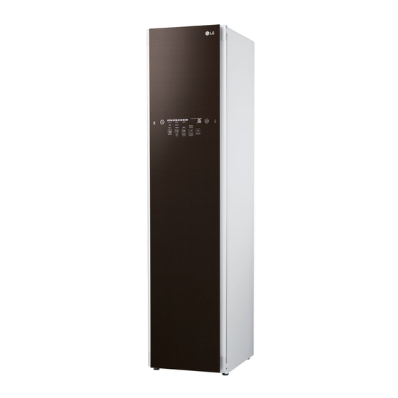
Contents Product Specifications ····················································································· 4 Name and Function of Parts ············································································ 6 Installation and Service Guide ······································································· 16 Styler Cycle and Usable Clothes ···································································· 17 Inspecting the Product ··················································································· 21 Heat Pump Cycle and Refrigerant ································································· 26 Function and Operating Principle of Cycle Components ······························ 36 Circuit Diagram ······························································································... - Page 4 Product Specifications Product name: electronic machine for maintain- ing clothes Rated power: 120V/60Hz Dimensions: 445(W)×585(D) ×1,850(H) Capacity: 4 clothes (top: 3, bottom: 1) Weight: 83Kg Product specifications may be changed by the manufacturer. Model Name Key Features Styling, sterilization, and drying S3RERB Additional Download Courses...
- Page 5 PRODUCT OVERVIEW PARTS interior light hooks for Pants Crease Care moving hanger interior light Pants Crease Care shelf holder door* shelf aroma filter steam nozzle hot air circulation vent water water supply tank drain tank drip tray * The door swing can be reversed by the installer to fit the installation location.
- Page 6 If the fit is too loose, it may result in vibration, noise, and damage to clothing. Note y Contact the store where the product was purchased or LG customer service at 1-800-243-0000 (1-888-542-2623 in Canada) if any accessories are damaged or missing. Accessories can be purchased separately online at http://www.lg.com/us y For your safety and for extended product life, use only authorized components.
- Page 7 Pants Crease Care feature. This cycle can • Clothing should be securely fastened, with be downloaded using the LG Smart Styler zippers and buttons closed, so that it does not app and used as the Downloaded cycle.
- Page 8 THE SHELF CHOOSING STYLER FEATURES Use the shelf when styling clothes or other items item how to style it that are difficult to hang or that may be damaged suit coat, blazer moving hanger by hang drying. coat, jacket (short) moving hanger moving hanger coat (long)
- Page 9 INSTALLATION INSTALLATION OVERVIEW Please read the following installation instructions first after purchasing this product or transporting it to another location. Check and choose the Level the Styler Reverse the door swing proper location (if needed) 100–130V only Connect to grounded outlet PRODUCT SPECIFICATIONS The appearance and specifications listed in this manual may vary due to constant product improvements.
- Page 10 UNPACKING THE STYLER • Remove tape and any temporary labels from the Styler before using. Do not remove any warning labels, the model WarNiNg and serial number label, or the Tech Sheet y Use two or more people to move and that is located under the front of the Styler.
- Page 11 INSTALLATION LOCATION REQUIREMENTS WarNiNg Read all installation instructions completely before installing and operating the Styler. It is important to review this entire manual before installing and using the Styler. The installation requires: y A grounded electrical outlet located within y A sturdy floor to support the total ap- 2 ft.
- Page 12 The following clearances are recommended for the Styler. Although the Styler has been tested for clearances of 1 inch (3 cm) on the sides 7 3/4 in. and rear, recommended clearances should be (20 cm) considered for the following reasons: y Additional space should be considered for ease of installation and servicing.
- Page 13 LEVELING THE STYLER WarNiNg y The Styler is heavy. Use two or more WarNiNg people if installing the rear leveling y To reduce the risk of injury to persons, feet. Failure to do so can result in back adhere to all industry recommended safety injury or other injury.
- Page 14 REVERSING THE DOOR 5 After the spikes have been installed, the Styler may need to be leveled again. It is possible to reverse the direction of the door If the carpet has very deep pile or padding, swing. This should be done by the installer at the the front feet may need to be extended time of installation, if desired.
- Page 15 ASSEMBLING THE DRIP TRAY 3 Place the adhesive side of the non-skid pad on the floor. Before using the Styler, insert the drip tray onto This side up the bottom of the cabinet. Adhesive 1 Hold the tray so the arrow and letter on side the front of the tray face up. Remove backing 2 Insert one side of the tray first, then the other. Push the tray until it slides 4 Recheck the Styler's levelness.
- Page 16 Unpack accessories. Unpack the shelf and hangers. For instructions on installing or using accessories, see Loading the Styler, pages 25-28. Accessories can be purchased separately from the LG Customer Information Center. Call 1-800-243-0000 (USA) or 1-888-542-2623 (Canada). Assemble the drip tray.
- Page 17 USING THE STYLER 1 PREPARE ITEMS • Wash clothes first, if needed. • No heat-sensitive items or items that can be damaged by exposure to water. See Choosing Styler-Safe Clothing, page 21. • Place items on hangers or the shelf. • Fasten buttons and close zippers to keep items on moving hangers and prevent damage.
- Page 18 SORTING LOADS Grouping Similar Items Fabric Care Labels • For best fabric care results, always treat fabrics with similar care requirements together. Most articles of clothing feature fabric care • Different fabrics have different care labels that include instructions for proper care. requirements, and some fabrics cannot be Below are some of the symbols that are relevant treated in certain Styler cycles or should be...
-
Page 19: Product Specifications
FABRIC CARE GUIDE = yes § = check label Refresh cycle Control Lock Control Lock Control Lock Gentle Sanitary fabric clothes comments cycle removing removing cycle wrinkles odors towels, socks, Wrinkles may underwear, remain in 100% jeans, cotton fabrics. cotton ●... - Page 20 FABRIC CARE GUIDE (CONTINUED) = yes § = check label Refresh cycle Gentle Control Lock Control Lock Control Lock Sanitary fabric clothes comments removing removing cycle cycle wrinkles odors suit lining, blouses, acetate ● ● ● ● neckties, pajamas thermal Lay clothes on underwear,...
-
Page 21: Name And Function Of Parts
CHECKING THE FILTERS BEFORE EVERY LOAD Checking the Lint Filter Changing the Aroma Sheet Always make sure the lint filter is clean before Use a dryer fabric softener sheet to add a starting a new load; a clogged lint filter will refreshing aroma to items. - Page 22 CHECKING THE WATER TANKS LOADING THE STYLER Check the water in the water tanks before use. cautioN The water supply tank must be filled with water before using the Styler. The Styler does not y Check all pockets to make sure that they work without water.
- Page 23 Hangers Using the Moving Hanger Insert hangers into slots and pull down to secure the The hangers that come with the Styler are for hook snugly. use with the Styler only. Any plastic or metal Hooks should fit down in the slots snugly to hanger that has a hook less than 5/32 in. (4 mm) prevent noise, vibration, or damage to items thick and hooks snugly into the indentations in during operation.
- Page 24 OPENING AND CLOSING THE PANTS USING THE PANTS CREASE CARE hook HANGER hanger 1 Open the Pants Crease Care by pressing on blades 1 To open, fold the hook down the icon on the side. toward the hanger blades to unlock and separate the blades. hook hook hanger blades hanger blades 2 Once pants are inserted, bring the blades together and rotate the hook up and away from the blades to lock them in place. 2 Hang the pants hanger on the hook above the Pants Crease Care that best fits the Hanging Pants On the Pants Hanger length of the pants being pressed.
- Page 25 Shelf • Hang the shelf on the shelf holder when treating long clothes such as coats or dresses. Use the shelf for clothes and items that cannot be placed on hangers. Do not stack items on the shelf. For best drying performance, use the shelf for a single item or smaller items with space between.
- Page 26 This portion of the display shows which stage of Place an NFC-equipped smart phone over this the styling cycle is currently underway (Preparing, icon to use the LG Smart Styler application using Heating, Steaming, Drying, or Sanitizing). NFC (Near Field Communication) tags. See ...
- Page 27 The default Downloaded cycle is the Ready to Go cycle. Download a new cycle in this position using the LG Smart Styler application on an NFC-equipped smart phone. See Downloading Styler Cycles, page 37. Press and hold for three seconds to activate the Smart Diagnosis™...
- Page 28 CYCLE GUIDE Cycle Processes Est. time Cycle Setting Clothing / Fabric Type Prepare Heat Steam Sanitize in Hr.: Min. suit, coat, school uniform, Normal scarf, wool, knitwear, outdoor/ performance clothing, towels, underwear, t-shirts, socks, jeans, Light jean jackets, lingerie, sportswear, ...
- Page 29 CHOOSING A CYCLE Special Care Night Care Styler cycles are designed to fit a variety of The Night Care cycle is a special extended situations. Select the cycle and setting that best Sanitary Heavy cycle. It runs the Sanitary Heavy match the load contents and desired results for cycle and then dries periodically every hour for an maximum performance and fabric care.
- Page 30 This is normal. • Download and use the LG Smart Styler app • The moving hanger will move even when only on a smart phone to confirm the current the shelf is being used.
-
Page 31: Installation And Service Guide
* Smart Diagnosis™ 2 A tone sounds to confirm the change. Use this function with the LG Smart Styler application on a smart phone or when contacting the LG service center to help diagnose problems with the Styler. See Using Smart Diagnosis™, page 44. -
Page 32: Styler Cycle And Usable Clothes
On function. 1 Look for the Tag On icon next to the Start/ Using Tag On with Apps Pause button on the control panel. Touch an LG Styler’s Tag On logo with an NFC- equipped smart phone, and the LG Smart Styler apps use the Tag On function. LG Smart Styler Install and run the LG Smart Styler app from... - Page 33 Downloading Styler Cycles LG Smart Styler’s Smart Download Cycle app allows you to download a cycle for later use. The cycle is available at the Downloaded cycle position on the control panel until another cycle is downloaded. 1 Install the LG Smart 2 Select the Smart Download 3 Click through the NFC info.
- Page 34 MAINTENANCE Cleaning the Lint Filter Always remove the lint from the filter after every REGULAR CLEANING cycle. See Checking the Lint Filter, page 22. WarNiNg If the lint filter has become very dirty or clogged, wash the lint filter in warm, soapy water and To reduce the risk of fire, electric shock, or allow to dry thoroughly before reinstalling. injury to persons when using this appliance, • Never operate the Styler without the lint filter.
- Page 35 3 Make sure the drainage nozzle connected to the water drain tank and the water supply hole connected to the water supply tank are not clogged. Drainage nozzle Water supply hole 4 Allow the outsides of the tanks to dry completely before reinstalling the tanks.
-
Page 36: Inspecting The Product
Inspecting the Product Pull out the power cord before inspecting the parts of the product. 5-1. Water Supply/Drain Pumps Water drain 1. Function tank 1) Supplying water to AG Water drain : Water supply tank → Water supply pump → AG pump Water supply tank... - Page 37 5-2. Steam Heater 1. Function 1) It heats the water inside the AG for steam injection. 2. Precautions 1) The heater should not be exposed to air (factors such as tilting and vibration should be considered to see if the heater is exposed to air). 2) Do not use the heater that was detached from the AG.
- Page 38 5-3. Main Fan 1. Function 1) Drying: It supplies the air that was heated by heat exchanger into the product and cir- culates it to dry the clothes that are wet. 2. Precautions 1) When the water penetrates into the motor, noise may occur. 2) The product may be damaged due to external impact such as vibration and overload.
- Page 39 5-4. LEV 1. Function 1) The LEV lowers the pressure of the refrigerant so that the refrigerant can evaporate easily from the evaporator, improving the refrigerant efficiency. 2) It adjusts the amount of refrigerant that flows into the evaporator. 2. Precautions 1) If the LEV is deformed due to the heat generated from the welding of LEV to the as- sembly, the LEV may not work properly in the Drying and Refresh modes.
- Page 40 5-5. Pulley Motor(Moving Hanger) 1. Function 1) Product improvement: The pulley motor shakes the clothes that are on the hanger to the left and right, improving the efficiency of wrinkle and odor removal. 2. Precautions 1) When the water penetrates into the motor, noise may occur. 2) The product may be damaged due to external impact such as vibration and overload.
-
Page 41: Heat Pump Cycle And Refrigerant
Heat Pump Cycle and Refrigerant 6-1. Heat Pump Cycle (Principles of Heat Pump/Refrigerant Gas Circulation) 6-1-1. Principles of Heat Pump Heat pump maintains the temperature higher than the ambient temperature. In order to achieve this, it requires insulated space, refrigerant R134a for absorbing heat, and a circulation circuit for controlling phase of the refrigerant (compressor, condenser, evaporator, etc.). - Page 42 6-1-3. Operation of Circulation Circuits Refrigerant gas status (inlet/ Part name Details of operation outlet) Compressor It compresses the refrigerant from low Low pressure gas → High pressure pressure (5 kgf/ ㎠ ) to high pressure (15 ~ 18 kgf/ ㎠ ). Temperature (30 ℃...
- Page 43 6-3. Solving the Product Noise 6-3-1. Reducing the Noise • Blocking the sound: Block the propagation path of the sound with high-density noise insulation mate- rial so that the sound cannot be heard. • (Effective in high-frequency range) • Using sound-absorbing material: It is similar to blocking, but uses styrofoam, glass wool, etc. for absorb- ing noise.
- Page 44 6-4. Conducting Major Repair of Heat Pump Cycle 6-4-1. Repair Work Standards for the Styler that Uses Refrigerant R134a Work Category Unit Work Standards Purpose Remarks Pipe parts: Within 1 hour When it is rainy, reduce the time to Opening time for pipe To prevent water from lower than half of the specified time.
- Page 45 - Vacuum degasification speed: 113 ℓ/min - Measure the cylinder for R134a provided by LG using the electronic Cylinder for R134a, refrigerant scale in vacuum state within ±5 g of the specified volume and inject the R134a, manifold gauge,...
- Page 46 6-4-3. Precautions When Performing Major Repair Category Precautions 1. Using tools Be sure to use the parts and tools that are designed for R134a. 1) Remove the remaining refrigerant at least 5 minutes after you turn off the styler. (Otherwise, the Internal oil may leak.) 2.
- Page 47 Category Precautions High pressure Low pressure 3. Vacuum degasification Key Point - Conduct the vacuum degasification while you operate the compressor when you suck up the refrigerant. (This way, refrigerant injection is easy and error-free.) Pipe connection Connect the red hose to the high pressure side and blue hose to the low pressure side. Vacuum sequence Open the valve and apply vacuum for 40 minutes, then close the valve.
- Page 48 6-4-5 Basic Guidelines for Major Repair 1) Follow the safety guidelines for handling gas. 2) Use the hot grill jig or wet towel when you perform welding so that you don't get burned. 3) Prevent the copper pipe from being oxidized due to overheating when you perform welding. 4) Make sure that the intake pipe and charging pipe are not mixed up when you conduct welding (high- efficiency pump).
- Page 49 6-4-7. Troubleshooting Flowchart Check the Check the The air is Normal rotation of hot air inlet. warm. compressor. The air is a Moisture not pro- little cold. vided LEV malfunction The air is Cycle Capillary tube not warm. clogged clogged LEV mal- Valve housing function...
- Page 50 6-4-8 Precautions When Servicing the Product 1) Cycle clogging and leakage • W hen you replace parts, perform welding, or charge refrigerant due to cycle clogging and leakage, be sure to replace the dryer so that the moisture inside the cycle is removed. Cycle clogging and leakage on the welded part Fix the clogging and perform welding on the leaked area Replace the dryer ...
-
Page 51: Function And Operating Principle Of Cycle Components
Function and Operating Principle of Cycle Components 7-1. Function and Operating Principle of Compressor (Reciprocating Piston Motor Motor-sustaining spring Lubricant Compressor contains lubricant that is applied to the piston part that compresses refrigerant gas from low pressure to high pressure and the motor part that operates the piston part. The lubricant lubricates and cools the piston and motor parts. - Page 52 7-2. Structure and Function of Overload Protection (O.L.P) Relay • Overload protection relay blocks the power that is supplied to the motor and protects the motor wiring when the temperature of compressor rises abnormally or overcurrent is applied to the compressor mo- tor.
- Page 53 7-3. LEV (1) Function - It lowers the pressure of refrigerant, decreasing the temperature of the evaporator. - It improves the efficiency of the compressor cycle. - It adjusts the amount of refrigerant that flows into the evaporator. (2) Operating Structure Hot air flowing Condenser Air coming from the...
-
Page 54
(3) Operating Principle If you adjust the rotating angle of the stepping motor, the outlet of the pipe repeatedly opens and closes due to the valve that is connected to the lower part of the rotor. Stopper Inlet Outlet
... -
Page 55: Circuit Diagram
Circuit Diagram Incorrect wiring may lead to abnormal, risky operation. Check if the product works properly after servicing it. Applied model: S3RERB... - Page 56 Incorrect wiring may lead to abnormal, risky operation. Check if the product works properly after servicing it. 적용 모델 : S3RERB Applied model: S3RERB...
-
Page 57: Things To Check Before Servicing
Things to Check before Servicing Symptoms Checkpoints Instructions “Is there enough water in the water supply Fill the water supply tank with water and put it [Feed Water] icon is tank?” back into the product. flickering. “Is the water supply tank in place?” Put the water supply tank back into the product. - Page 58 "When "Is there any sleeve of the clothes Operate the product again steam or wind comes out that are being styled nipped in the door?" after putting back the clothes stuck in the door. near the door" “Did you press the Power button?” Press the Power button.
-
Page 59: Diagnosis And Error Table
Diagnosis and Error Table 10-1. Diagnosis Approaching Test Mode : Refresh Key + Sanitary Key + Power Key Operate/Pause Things to Check How to Check Remarks U:XX – Main Version(XX) D:XX – Display Version(XX) Enter the LQC test mode. NC error should not occur. C:XX - Inverter Version(XX) Keep '1' on at the 18:88 LED lamp should turn on normally. - Page 60 10-2. Error Table Triggered or not Trigger General Lifetime Duct Out Thermistor Open is detected Duct Out Thermistor General: At Comp On state, temperature Comp Thermistor difference is less than 20 for 10 minutes Duct In Thermistor Open is detected Duct In Thermistor Steam Thermistor Open is detected Steam Thermistor...
-
Page 61: Product Flowchart And Cycle Characteristics
Product Flowchart and Cycle Characteristics 11-1. Product operating FLOW CHART Drain Feed Moving Hanger Tank Tank Feed Inner Case Pump Main Check Valve Valve Steam Comp Nozzle Valve Inlet Drain Comp Sump Duct Pump Water Steam Refrigerant Moving Hanger Assembly Belt Hall Motor... - Page 62 11-2. Cycle Characteristics - Styling Steam Stay Cooling Drying Steam Heat (P180/M1200~ 2(M1050 ~ 1800) 1800) Normal 9 (M 1050) 2 (P180/M1050) 1 (P180/M1800) 2(M1050 ~ Light 4 (M 1050) 1 (P180/M1800) (P180/M1200~ 1800) Heavy 13 (M 1050) 5 (P200/M1050) 3 (P200/M1800) 1800) 2(M1050 ~...
- Page 63 11-2. Cycle Characteristics - Drying Steam Stay Cooling Drying Steam Heat 120 (P120/ Normal M1200~1800) 150 (P120/ Delicates M1600) 30~150 (P120/ Time Dry M1200~1800) Moving hanger Operation: 30 seconds after the cycle started operation Water supply/ Comp Water supply/drain pump drain pump STEAM HEATER MAIN FAN...
- Page 64 11-2. Cycle Characteristics - Sanitary...
- Page 65 11-2. Cycle Characteristics - Download...
-
Page 66: Service Flow For Symptoms
2. Did you use multiple electronic devices at the same time? If you use the LG Styler together with a high-capacitance home appliance (such as a heater, dryer, drum-type washing machine, or an air conditioner), the total amount of electricity in use can exceed the amount of electricity allowed for your house, which in turn causes the breaker to go down. - Page 67 12-2. When Feed Water LED is blinking Is the water supply tank full of water? Fill the water in water supply tank and operate. Is the water supply tank properly connected to the product? Press the water supply tank to check whether it is ※...
- Page 68 Is the water supply pump connector (WH2) properly assembled? Connect the connector. Is there check valve on the AG? Remove the check valve. Product number: G Are the AG water level sensor connectors (WH2, WH1) Connect the connector. connected? Are the main PCB connectors (WH8, YL4, BL12) properly Connect the connector.
- Page 69 12-3. When Discard Water LED is blinking Is the drain outlet of the check valve on the Is the water drain tank full of water? Replace the check valve. water drain tank open? Is the power consumption of water drain pump 10 or above? Press the water supply tank to check whether it is ...
- Page 70 Is the water drain pump connector properly connected? Connect the connector. (Check if it is assembled improperly or not assembled.) Is the lower sump of inlet duct full of water? Replace the water level sensor. Is the sump filter clogged with foreign substances? Remove foreign substances and check again.
- Page 71 12-3. When Discard Water LED is blinking Symptom: Dust is deposited on the sump filter and water is not drained prop- erly. Floater deviates from the detection range of reed switch and the Discard → Water error occurs. Solution: Clean the filter. Replace the filter if it is damaged.
- Page 72 12-4. When Door Open LED is blinking Does the product move a lot when you shake it? Adjust the legs to make the product level and ※ Check if the floor is level. check again. Is the front/rear vent clogged with clothes when you open the door? Remove the clothes and check again.
- Page 73 Is the reed switch at the top of the case in normal position? Attach the reed switch properly. Is the main PCB connector (RD7) properly assembled? Connect the connector. Replace the door ASM.
- Page 74 12-5. Water leak 1) Leakage in the Product Is the tray properly installed? Install the tray properly. Does the leakage occur in water supply tank? Check for the leakage of the water supply tank. Is the gasket of the door ASM properly assembled? Reassemble the gasket and check again.
- Page 75 12-6. Water leak 1) Leakage in Water Supply Tank Does the leakage occur on the fused area when the water is filled to half? Does the leakage occur on the lower part of water tank when the water is filled to half? Is the seal attached to connector hose when you remove the water and detach the hose?
- Page 76 12-7. Deformation of Water Supply/Drain Tanks Is the water supply/drain tanks crushed or deformed? Check the hose condition and replace the hose if necessary. Is the steam outlet hose properly connected without ※ If the hose is clogged, steam flows backward and water bending/twisting/folding? supply/drain tanks are deformed due to the heat.
- Page 77 12-9. Vibration Adjust the height of the product leg to make the product Is the product on the floor level? level. • Be sure to install the product on the firm, flat surface. Install the Are you operating the product after product on hanging an empty hanger? the firm, flat...
- Page 78 12-10. TE1 Are the main PCB connector (BL12) and thermistor connector (WH2) at the top Connect the connector. of the condenser properly assembled? Replace the thermistor. 12-11. TE2 Assemble the thermistor. Is the COMP_THERMISTOR properly assembled? (Insert it to the pipe.) (deviation, etc.) Is the thermistor connector (WH2) properly connected? Connect the connector.
- Page 79 Is the LEV connector (WH5) properly assembled? Connect the connector. Is the comp connector (WH3) properly assembled? Connect the connector. Connect the connector. Are the main PCB connectors (RD3, BL12, NA5) properly connected? Do you feel the vibration of comp 1 minute after starting the Drying cycle? Replace comp and perform repair.
- Page 80 12-12. TE3 Are the main PCB connector (BL12) and thermistor connector (BL2) at the top of Connect the connector. the evaporator properly assembled? Replace the thermistor. 12-13. TE5 Assemble the thermistor. Is the EVAPORATOR_THERMISTOR properly assembled? (Insert it to the pipe.) (deviation, etc.) Connect the connector.
- Page 81 12-14. E1 Replace the thermistor. Is the resistance measured on the AG thermistor 49 kΩ ±8.7 % (25 )? Is the water supply path [water supply hose - water supply pump - water supply Replace the hose and faulty component. valve - AG] properly assembled? (Check if it is clogged.) ※...
- Page 82 12-15. E4 Is the AG thermistor connector (WH2) properly assembled? Connect the connector. Is the resistance on both ends of AG heater 29.5 Ω ± 7 %? Replace the AG. (check if the heater is faulty.) Assemble the wiring properly. Is the main PCB connector (BL12) properly assembled? Replace the main PCB.
- Page 83 12-16. LE Is the main PCB connector (YL3, NA4) and the connector (WH7) related to the Connect the connector. motor properly assembled? Does the interference occur between housing blower and 1. Disassemble the housing blower and check if the impeller? impeller tightening screw (left) is removed.
- Page 84 12-17. LE2 Replace comp and LEV and perform repair. 12-18. AE Is the comp connector (WH3) properly assembled? Connect the connector. (Check if it is disconnected or not connected at all.) Connect the connector. Is the main PCB connector (RD3) properly assembled? Replace the main PCB.
- Page 85 12-19. Moving Hanger not in Proper Position Attach the magnet and check again. Is the magnet properly settled on the pulley idle? ※ Use silicon when mounting the magnet. Is the hall sensor properly settled? Attach the hall sensor. Is the hall sensor connector (RD3) connected? Connect the connector.
- Page 86 12-20. Moving Hanger Does not Move Is the hanger ASM properly assembled? Reassemble the hanger ASM B. Is the V-belt properly assembled? Assemble the V-belt. Is the motor connector (RD3) connected? Connect the connector. Is the motor connector (BL3) connected? Connect the connector.
- Page 87 12-21. Problem with Wrinkle Removal #1 0. First thing you need to check Did you use the hanger supplied with the product? Check if there is any faulty component. Is the thickness of the hanger hook 4 mm or below? Check if there is any faulty component.
- Page 88 You need to use a regular iron to straighten the shirt made of 100 % cotton. LG Styler does not directly apply the heat on the clothing like a regular iron, but uses steam and a moving hanger to remove wrinkles indirectly. So it cannot completely remove the wrinkles on the shirt made with cotton.
- Page 89 You need to use a regular iron to straighten the shirt made of 100 % cotton. • LG St y ler do es not dire c tly apply the heat on the clothing like a re gu - lar iron, but uses steam and a moving hanger to remove wrinkles indirectly.
- Page 90 12-24. Problem with Drying #1 Do you hear noise from the comp 30 - 60 seconds Check the connection of related harness connectors. after turning on the power and starting the Drying Comp connector (WH3), main PCB connector (RD3) course? Does the pipe temperature rise to 60 - 70 ...
- Page 91 12-25. Problem with Drying #2 • Clothing is not completely dry after drying. Moisture remains on the clothing. 1. Use the Drying course only after you completely wrung the water from the clothing. If you do not completely wrung the water from the clothing, time required for drying may be extended, raising the electric bill.
- Page 92 12-26. Problem with Drying #3 • Clothing is not completely dry after drying. Moisture remains on the clothing. In the case of thick clothing such as jeans and blankets, run the Drying course once more after turning the clothing inside out.
- Page 93 12-27. Problem with Drying #4 • The clothes does not dry well. Did you by any chance use the Styling course for drying? Styling course is not intended for drying. It does remove steam moisture used for wrinkle and odor removal for a short time at the beginning, but its purpose is not drying.
- Page 94 Do not reuse the water in the drain tank. Purchasing Aroma Sheet : Aroma sheet can be purchased at KRW 9,900 for 1 box at the LG Best Shop. There are 30 sheets in one box and you can change them once every two or three cycles.
- Page 95 12-29. Problem with Odor Removal #1 • Odor does not go away after Styling. If the clothing is kept for 1 - 2 years inside the wardrobe, odor may penetrate deep into the clothing and the steam may not perfectly remove the odor. Perform the Styling as soon as odor permeates the clothing.
- Page 96 12-30. Problem with Accessories #1 • Why do you give only 2 hangers with the Styler? Can I use commercially available hangers? Hangers provided with the product include one for man and one for woman. However, some clothing such as babywear may not fit on the hanger. In this case, you can use the commercially available hanger, which is why we only provides you with two hangers.
- Page 97 12-31. Problem with Accessories #2 The following accessories can be additionally purchased from the LG Best Shop or LG service center. One hanger: KRW ????? A pair of pants: KRW ????? One shelf: KRW ?????
- Page 98 12-32. Vibration and Noise #1 • The Styler moves left and right when it operates. If the product is not level, it may move left and right due to the movement of the moving hanger and may cause the door to open. In this case, rotate the levelling leg at the bottom of the product to adjust the level.
- Page 99 LG Dios refrigerator I can hear boiling sound when the product operates. The Styler has a 'steam generator' just like a LG washing machine. The steam generator makes the sound to boil water and make steam, which is a normal phenom- enon and not a malfunction.
- Page 100 12-34. Vibration and Noise #3 • I can hear rattling noise when the product operates. Take out unused hangers from the moving hanger and put them on the shelf upside down.. The moving hanger in the Styler performs 200 times of reciprocating motion per minute to improve the performance of the Styler.
- Page 101 12-35. Clothing Deformation #1 • I heard that more steam is produced when I use the Styling-Strong option. Doesn't this damage the cloth- ing? • Doesn't the hot steam damage the clothing? If you select the Styling-Strong option, more steam is produced, but the steam temperature is the same. Therefore, the amount of moisture permeating the clothing increases, but the steam temperature stays the same.
- Page 102 12-36. Clothing Deformation #2 • Clothing is stretched. Moving hanger moves left and right in most of the Styling courses. This is to make more steam particles penetrate into the clothing. Knitwear or wool clothing may stretch more due to the movement of the moving hanger depending on how they are weaved.
- Page 103 12-37. Clothing Deformation #3 • The clothes produce fluffs. / The clothes has shrunk. Hang the hangers on the moving hanger in a way that the hangers face the same direction. If you hang the hangers in a way that they face each other, the clothes may bump into each other as the moving hanger moves, producing fluffs.
-
Page 104: Changing The Door Direction
Changing the Door Direction • Be sure to wear long gloves. Otherwise, it may cause injury. • The door is very heavy. Be careful not to drop it. Otherwise, it may cause injury. • When you work on the ladder, be careful not to fall down. •For the details on the reversible kit, refer to the picture in the last chapter. - Page 105 4. Loosen 5 screws and remove the cover. Cover 5. Remove the connector connected to the display PCB and the red and white connectors connected to the reed switch and remove the cover. 6. Pull out the hinge cap cover at the bottom and re- move it.
- Page 106 9. Loosen 4 screws at the top of the door and detach 2 cap covers from the protective cover. Cap cover Cap cover Protective cover 10. Loosen 2 screws that fix the hinge and detach the hinge from the hinge cap cover. Hinge cap cover 11.
- Page 107 13. Attach the 'L' cap cover for the hinge side and switch the position of the cover on the opposite side in a diagonal direction and attach it. 'L' cap cover 'L' cap cover 14. Press the pants press to open it. 15.
- Page 108 18. Loosen 8 screws and remove the cap covers on both sides. 19. Loosen 4 screws on the hinge side, remove the Hinge bracket hinge bracket, and detach the pants press. Locker 20. Loosen 2 screws on the locker side and remove the locker.
- Page 109 24. Loosen two top hinge fixing screws and two bottom hinge fixing screws completely to Cap cover protrude them approx. 15 mm on the op- posite side. 25. Loosen the screws and attach the cap cover on the opposite side. 26.
- Page 110 28. Insert the wire fixing slider to the hole below the hinge and fix the top/bottom hinge screws. Caution: When you do this, be sure to hold the ※ door firmly. Check if the wiring is pinched or bent when attaching the door. 29.
-
Page 111: Reversable Kit(Svc Loc : Svc01)
33. Assemble the water supply/drain tanks. 34. Move to the top of the product, place the top cover, and tighten 9 screws except for the hinge side. 35. Assemble the 'L' cap cover and tighten the screws. Cap cover (L) 36. -
Page 112: Disassembly
Disassembly • Be sure to pull out the power cord before disassembly. Disassemble main PCB Disassemble machine room → 1. Remove the aroma filter. 2. Remove the antibacterial water supply/drain tanks. 3. Hold both sides of the grille and detach it to remove the filter. - Page 113 4. Loosen 6 screws and remove the connector. 5. Loosen 6 screws and remove the cover. 6. Pull the door decoration and cap cover to detach them. Cover Cap cover Door decoration 7. Remove 4 connectors except for the blue connec- tor.
- Page 114 11. Remove the hose that is connected to the frame. 12. Move to the back side of the product and loosen 6 screws to remove the cover. 13. Remove 2 hoses. 14. Loosen 6 screws. 15. Hold the handle of the ma6chine room, lift it slightly and pull it outside.
- Page 115 • Disassembling main PCB 1. Move to the back side of the product and loosen 6 screws to remove the cover. 2. Remove 2 hoses. 3. Remove 3 connectors that are connected to the generator ASM. 3. Loosen 2 screws and push the generator ASM to the left and pull it back to place it on top of the main PCB.
- Page 116 4. Remove 2 connectors connected to the genera- tor ASM and remove the generator ASM. 5. Loosen 1 screw connected to the power cord holder and remove the power cord to the right. 6. Remove the connector connected to the noise Noise filter filter and loosen the grounding screw.
- Page 117 9. Loosen the fixed wiring and pull out the PCB ASM from the product. 10. Loosen 1 screw and remove the cover. 11. Loosen the hook and open the PCB ASM. 12. Detach all the housings that are connected to the main PCB.
- Page 118 • Detaching moving hanger 1. Push the holder attached to the moving hanger outward and remove the moving hanger. 2. Remove 2 screws. 3. Loosen 10 screws and remove top cover and cap cover. 4. Remove the belt.
- Page 119 5. Loosen the pulley fixing bolt to remove the pul- ley. 6. Remove 2 connectors. 7. Loosen 8 screws and remove the driving compo- nent.
- Page 120 • Detaching display PCB 1. Press and open the pants press. 2. Insert the awl into the gap on the cap cover and re- move the cap cover. 3. Loosen 2 screws at the position where the detached cap cover was. 4.
-
Page 121: Exploded View And Service Part Number
Exploded View and Service Part Number B115 A150 A230 A088 A165 A160 A210 A170 A175 A225 D150 A151 B025 A076 A080 A185 A050 A087 A090 A065 A086 A070 A093 A060 A055 A532 A531 A095 A530 A540... - Page 122 B082 B180 B115 B160 B090 B080 B150 B190 B112 B035 B110 B036 B030 B100 B020 B130 B036 B045 B040 B120 B046 D300 D400 D151 A150 D152 A183 D200 A265 D110 A112...
- Page 123 A115 A100 A120 A240 A110 A250 A125 A195 A188 A190 A105 A200 A260...
- Page 124 A330 A320 A370 A390 P116 A445 A346 P110 A325 P200 A341 P135 P130 P150 P170 P300 P136 P175 P140 P115 A400 A391 A420 A410 A390 A440 P100 P120 A335 A360 A320 A340 A345 A300...
- Page 125 C100 B220 B230 B210 A373 C010 A540 C015 SVC01 C020...
-
Page 126: Refrigerant
M120 M385 A430 M340 M330 M450 M455 S305 M155 S302 S301 M560 M465 M480 M330 M156 M570 S303 M150 M440 M280 S304 M440 M475 M460 M245 M310 M060 M250 M260 M270 M240 M320 M435 M425 D150 *Refrigerant - M135... - Page 127 A135 A140 M080 A220 M390 M405 M295 M195 M290 M196 M180 M235 M165 K351 M230 M175 M105 M155 M400 M130 M140 M430 A145 M160 A485 M225 M550 M200 M170 A130 M226 M085 M345 M420 M090 M125 M110 M115 M410 M485 M145 M375 A500...
-
Page 128: Things To Check After Repair
Things to Check after Repair • If you replaced or repaired any part, be sure to check the followings and conduct test driving (10. refer to the Diagnosis section) to see if the product functions properly. 1) Checking insulation resistance Pull out the power cord from the outlet and check the insulation resistance between the power plug and the ground wire of the main body. - Page 129 MEMO...
- Page 130 MEMO...
- Page 131 MEMO...
- Page 132 MFL66987013...