1
2
3
4
5
6
7
8
9
10
11
12
13
14
15
16
17
18
19
20
21
22
23
24
25
26
27
28
29
30
31
32
33
34
35
36
37
38
39
40
41
42
43
44
45
46
47
48
49
50
51
52
53
54
55
56
57
58
59
60
61
62
63
64
65
66
67
68
69
70
71
72
73
74
75
76
77
78
79
80
81
82
83
84
85
86
87
88
89
90
91
92
93
94
95
96
97
98
99
100
101
102
103
104
105
106
107
108
109
110
111
112
113
114
115
116
117
118
119
120
121
122
123
124
125
126
127
128
129
130
131
132
133
134
135
136
137
138
Quick Links
Honeywell International Inc.
400 Maple Grove Road
Ottawa, Ontario, K2V 1B8
Canada
CAGE: 38473
Telephone: 800-601-3099 (Toll Free U.S.A./Canada)
Telephone: 602-365-3099 (International Direct)
Website:
www.myaerospace.com
System Description, Installation, and Maintenance Manual
This guide provides procedures for installation, configuration, and operation of the equipment listed below.
Model
Low Gain Antenna System
AMT-3500 Intermediate Gain Antenna System
AMT-700 High Gain Antenna System
AMT-3800 High Gain Antenna System
AMT-1800 Intermediate Gain Antenna System
AMT-1800 Intermediate Gain Antenna System with CCU-200
AMT-1800 Intermediate Gain Antenna System with CNX-250
AMT-3500 Intermediate Gain Antenna System with CNX-200
AMT-1800 Intermediate Gain Antenna System with CNX-200
Export Control
These items are controlled by the U.S. government and authorized for export only to the country of ultimate
destination for use by the ultimate consignee or end-user(s) herein identified. They may not be resold, transferred, or
otherwise disposed of, to any other country or to any person other than the authorized ultimate consignee or
end-user(s), either in their original form or after being incorporated into other items, without first obtaining approval
from the U.S. government or as otherwise authorized by U.S. law and regulations.
Publication Number MN-0000042, Revision F
© Honeywell International Inc. Do not copy without express permission of Honeywell.
Legal Notice
ECCN: 7E994.
ASPIRE-200
Part Number
1541-K-1015-01
1541-K-1007-01
1541-K-1006-01
1541-K-1006-02
1541-K-1007-42
1541-K-1007-02
1541-K-1007-32
1541-K-1007-11
1541-K-1007-12
23-15-45
Page T-1
6 May 2011
Revised 28 Feb 2018

Related Manuals for Honeywell ASPIRE-200


Summary of Contents for Honeywell ASPIRE-200
- Page 1 U.S. government or as otherwise authorized by U.S. law and regulations. ECCN: 7E994. 23-15-45 Page T-1 Publication Number MN-0000042, Revision F 6 May 2011 Revised 28 Feb 2018 © Honeywell International Inc. Do not copy without express permission of Honeywell.
- Page 2 1541-K-1006-51 AMT-3800 High Gain Antenna with CNX-200 1541-K-1006-12 AMT-3800 High Gain Antenna with CNX-250 1541-K-1006-32 AMT-3800 High Gain Antenna with CNX-900 1541-K-1006-52 Page T-2 23-15-45 28 Feb 2018 © Honeywell International Inc. Do not copy without express permission of Honeywell.
- Page 3 Materials represents your acceptance of the terms of this License Agreement. 1. License Grant - If you are a party to an applicable written agreement with Honeywell relating to the repair or maintenance of the subject Honeywell Product, subject to your compliance with the terms and conditions of this License Agreement, Honeywell hereby grants you, and you accept, a limited, personal, non-transferrable, non-exclusive license to use these Materials only in accordance with that agreement.
- Page 4 U.S. Government. You may not design or manufacture a Honeywell part or detail of a Honeywell part, to create a repair for a Honeywell part, design or manufacture any part that is similar or identical to a Honeywell part, compare a Honeywell part or design of a Honeywell part to another part design, or apply for FAA PMA or other domestic or foreign governmental approval to manufacture or repair a Honeywell part.
- Page 5 SYSTEM DESCRIPTION, INSTALLATION, AND MAINTENANCE MANUAL Aspire-200 10. Remedies - Honeywell reserves the right to pursue all available remedies and damages resulting from a breach of this License Agreement. 11. Limitation of Liability - Honeywell makes no representations or warranties regarding the use or sufficiency of the Materials.
- Page 6 THE LIFE OF THE COMPONENTS. INCORRECTLY FABRICATED SPECIAL TOOLING OR TEST EQUIPMENT CAN RESULT IN DAMAGE TO THE PRODUCT COMPONENTS OR GIVE UNSATISFACTORY RESULTS. Page T-6 23-15-45 28 Feb 2018 © Honeywell International Inc. Do not copy without express permission of Honeywell.
- Page 7 Our products are under continuous research and development. Any information may therefore be changed without prior notice. Honeywell reserves the right to make improvements or changes in the product described in this manual at any time without notice. While reasonable efforts have been made in the preparation of this document to assure its accuracy, Honeywell assumes no liability resulting from any errors or omissions in this document, or from the use of the information contained herein.
- Page 8 SYSTEM DESCRIPTION, INSTALLATION, AND MAINTENANCE MANUAL Aspire-200 Blank Page Page T-8 23-15-45 28 Feb 2018 © Honeywell International Inc. Do not copy without express permission of Honeywell.
- Page 9 When revisions are received, insert revised pages, record the date, and initial. Revision Issue Date Inserted by Revision Issue Date Inserted by Number Date Inserted (initial) Number Date Inserted (initial) Page 1 23-15-45 28 Feb 2018 © Honeywell International Inc. Do not copy without express permission of Honeywell.
- Page 10 SYSTEM DESCRIPTION, INSTALLATION, AND MAINTENANCE MANUAL Aspire-200 Blank Page Page 2 23-15-45 28 Feb 2018 © Honeywell International Inc. Do not copy without express permission of Honeywell.
- Page 11 Installation, and Maintenance Manual D2014100000 20 Oct 2014 Aspire-200 High Speed Data Unit (HDU), PN 1541-A-3000-01 - Loss of Navigational Data Disabling SwiftBroadband Channel Page SBL-1 23-15-45 28 Feb 2018 © Honeywell International Inc. Do not copy without express permission of Honeywell.
- Page 12 SYSTEM DESCRIPTION, INSTALLATION, AND MAINTENANCE MANUAL Aspire-200 Blank Page Page SBL-2 23-15-45 28 Feb 2018 © Honeywell International Inc. Do not copy without express permission of Honeywell.
- Page 13 * An asterisk indicates pages changed, added, or deleted by the current revision. F indicates a right foldout page with a blank back. Section Page Date 28 Feb 2018 Page LEP-1 23-15-45 28 Feb 2018 © Honeywell International Inc. Do not copy without express permission of Honeywell.
- Page 14 SYSTEM DESCRIPTION, INSTALLATION, AND MAINTENANCE MANUAL Aspire-200 Blank Page Page LEP-2 23-15-45 28 Feb 2018 © Honeywell International Inc. Do not copy without express permission of Honeywell.
- Page 15 EQUIPMENT DRAWINGS 1. HDU-200........................3-1 2. HDU Rear Connector..................... 3-3 3. IPLD ........................3-5 4. SCM ........................3-7 5. Omni Blade Antenna ..................... 3-9 Page TC-1 23-15-45 28 Feb 2018 © Honeywell International Inc. Do not copy without express permission of Honeywell.
- Page 16 (1) Selecting a Location for the CNX-900 Router with Personality Module .......4-6 (2) Cooling Requirements ....................4-6 (3) Clearance and Accessibility Requirements ..............4-7 (4) Installation Notes ......................4-7 H. Blade Antenna ........................4-7 Page TC-2 23-15-45 28 Feb 2018 © Honeywell International Inc. Do not copy without express permission of Honeywell.
- Page 17 D. Configuring the APN ......................5-4 E. Configuring NAV .......................5-5 F. Entering the Antenna Alignment Parameters: ROLL, PITCH, ROTATION ......5-7 2. Configuring Dialers ....................5-9 Page TC-3 23-15-45 28 Feb 2018 © Honeywell International Inc. Do not copy without express permission of Honeywell.
- Page 18 9. CNX-200Series 2 Network Accelerator ..............A- 10. CCU-200 ........................A- 11. CNX-250......................A-12 12. CNX-900......................A-14 APPENDIX B: GLOSSARY ....................... B-1 1. Abbreviations ........................B-1 Page TC-4 23-15-45 28 Feb 2018 © Honeywell International Inc. Do not copy without express permission of Honeywell.
- Page 19 Table 4-1 Carlisle Kits ........................ 4-2 Table 4-2 IPLD Connectors......................4-3 Table 4-3 Cable Shielding and Termination Specifications............4-17 Table 6-1 VT100 Scenario Report Content ................6-4 Page TC-5 23-15-45 28 Feb 2018 © Honeywell International Inc. Do not copy without express permission of Honeywell.
- Page 20 SYSTEM DESCRIPTION, INSTALLATION, AND MAINTENANCE MANUAL Aspire-200 Blank Page Page TC-6 23-15-45 28 Feb 2018 © Honeywell International Inc. Do not copy without express permission of Honeywell.
- Page 21 Figure 6-4 Port Antenna Maintenance Word Report ..............6-6 Figure 6-5 Port Antenna Status Word ..................6-7 Figure 6-6 Channel Card THA Codes Report ................6-7 Page TC-7 23-15-45 28 Feb 2018 © Honeywell International Inc. Do not copy without express permission of Honeywell.
- Page 22 SYSTEM DESCRIPTION, INSTALLATION, AND MAINTENANCE MANUAL Aspire-200 Blank Page Page TC-8 23-15-45 28 Feb 2018 © Honeywell International Inc. Do not copy without express permission of Honeywell.
- Page 23 This manual provides detailed information for avionics technicians about the wiring, installation, and setup of every component of the Aspire-200. The installer is responsible for the approval and certification of system components on the aircraft, and for the installation of wiring in the aircraft.
- Page 24 This manual includes the following sections: • Introduction—information about the Aspire-200, the Inmarsat network and its services • Equipment Drawings—outline drawings of every piece of equipment available with the Aspire-200, and Page 1-2 23-15-45 28 Feb 2018 © Honeywell International Inc. Do not copy without express permission of Honeywell.
- Page 25 System Setup—information and procedures for setting up the system after installation • Troubleshooting—troubleshooting information and where to find it • Specifications—environmental specifications for every piece of equipment available with the Aspire-200 • Glossary. 4. Precautions When working with AMT-1800, AMT-3500, AMT-3800, and AMT-700 antennas, be aware of the following warnings and cautions.
- Page 26 SYSTEM DESCRIPTION, INSTALLATION, AND MAINTENANCE MANUAL Aspire-200 Blank Page Page 1-4 23-15-45 28 Feb 2018 © Honeywell International Inc. Do not copy without express permission of Honeywell.
- Page 27 INTRODUCTION About the Aspire System The Aspire-200 connects to the Inmarsat satellite network and provides data and voice services to the aircraft cabin. You can install the Aspire-200 with various antennas, and each variation of the system provides a different level of service. With higher gain antennas, higher rates of transfer are possible, and you can access information faster and use applications that require higher bandwidth.
- Page 28 “Introduction to the Cabin Network” on page 2-6, “eNfusion® CNX-200 Interfaces” on page 2-8, and the CNX Series 2 Network Administrator’s guide, MN-1110-50348. High data rate (HDR) software is available as an upgrade to the Aspire-200 kit. You can install the HDR software to enhance Inmarsat L-band services. For HGA installations, the upgrade results in up to 650 kbps per SBB channel compared to the previous maximum data rate of up to 432 kbps.
- Page 29 Hardware Table 2-2 provides an overview of specifications for other components of the ASPIRE-200. The documentation for each component provides detailed specifications. Page 2-3 23-15-45 28 Feb 2018 © Honeywell International Inc. Do not copy without express permission of Honeywell.
- Page 30 4.3 pounds (1.95 kg) maximum Power +28 VDC @ 1.25 amps maximum 30 W maximum (Typical 15 W) Software RTCA/DO-178B Level D Page 2-4 23-15-45 28 Feb 2018 © Honeywell International Inc. Do not copy without express permission of Honeywell.
- Page 31 12.7 by 3.7 by 8.5 in. (323 by 94 by 216 mm) including mounting feet Weight 8.6 pounds (3.9 kg) Voltage 28 VDC Page 2-5 23-15-45 28 Feb 2018 © Honeywell International Inc. Do not copy without express permission of Honeywell.
- Page 32 B. Introduction to the Cabin Network The cabin network enables aircraft operators to offer various data and voice services to passengers in the aircraft cabin. The Aspire-200 can distribute the various services to the aircraft cabin and connect the users to ground data and voice networks.
- Page 33 • Each component is a LRU. D. Aspire-200 User Interfaces The Aspire-200 provides various interfaces to users in the cabin and users who set up and maintain the system. • ISDN 64k—access to ISDN services that you can wire directly to a computer or ISDN phone, or distribute through an ISDN router or terminal adapter.
- Page 34 Three Gigabyte Ethernet LAN ports for connectivity with high-performance systems such as CMS or IFE • Two additional Fast Ethernet LAN ports • Three Fast Ethernet ports for WAN connectivity Page 2-8 23-15-45 28 Feb 2018 © Honeywell International Inc. Do not copy without express permission of Honeywell.
- Page 35 80Gb solid state media storage. • Aspire-200 Connections to Aircraft The Aspire-200 communicates with various systems in your aircraft to control the antenna and distribute resources to its subsystems. (1) Power 28V aircraft power supplies the HDU, the IPLD, and all the antennas except the Omni Blade antenna and the AMT-3500 IGA (115 VAC).
- Page 36 Longitude GNSS, Hybrid, or Autonomous 175 or 112 Ground Speed GNSS, Hybrid, or Autonomous 137 or 103 Track Angle True GNSS, or Autonomous Page 2-10 23-15-45 28 Feb 2018 © Honeywell International Inc. Do not copy without express permission of Honeywell.
- Page 37 Inmarsat is an international organization that operates and maintains multiple geostationary satellites and satellite networks. Inmarsat networks provide services for aviation, shipping, and land-mobile terminals. Inmarsat provides information about satellite beam coverage at www.inmarsat.com. Page 2-11 23-15-45 28 Feb 2018 © Honeywell International Inc. Do not copy without express permission of Honeywell.
- Page 38 SYSTEM DESCRIPTION, INSTALLATION, AND MAINTENANCE MANUAL Aspire-200 The Aspire-200 can access services from two of Inmarsat’s satellite networks. The I-3 satellite network provides Swift 64 services, and the I-4 satellite network provides SwiftBroadband (SBB) services. Throughout 2018, Inmarsat will transition Swift64 services to the I-4 network and then decommission the I-3 network.
- Page 39 BlackBerry™ Email Streaming Video NOTE: If you have upgraded your Aspire-200 system with HDR software, data rates increase up to 450 kbps for an IGA installation, and up to 650 kbps for an HGA installation. 6. About Installation and Registration There are several steps to perform before you can use your Aspire-200.
- Page 40 Aspire-200 6. Subscribe to a service plan from a SwiftBroadband or Swift 64 Service Provider. If an HDR upgrade has been installed on the Aspire-200 System, ensure the applicable keys have been provisioned to use the HDR system with the Inmarsat network.
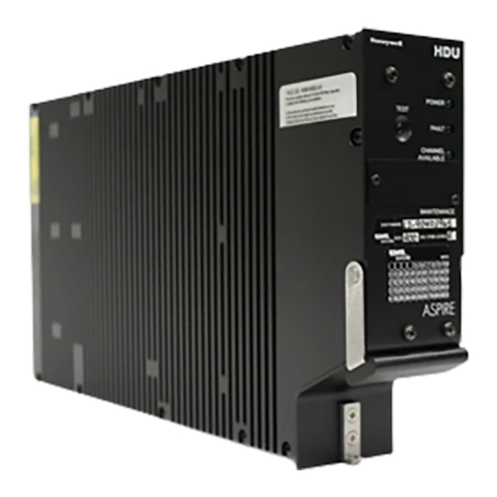
- Page 41 SYSTEM DESCRIPTION, INSTALLATION, AND MAINTENANCE MANUAL Aspire-200 EQUIPMENT DRAWINGS This section includes outline drawings of every component in the Aspire-200. 1. HDU-200 Figure 3-1 HDU Outline Drawing 23-15-45 28 Feb 2018 © Honeywell International Inc. Do not copy without express permission of Honeywell.
- Page 42 SYSTEM DESCRIPTION, INSTALLATION, AND MAINTENANCE MANUAL Aspire-200 Blank Page 23-15-45 28 Feb 2018 © Honeywell International Inc. Do not copy without express permission of Honeywell.
- Page 43 SYSTEM DESCRIPTION, INSTALLATION, AND MAINTENANCE MANUAL Aspire-200 2. HDU Rear Connector Figure 3-2 HDU Rear Connector 23-15-45 28 Feb 2018 © Honeywell International Inc. Do not copy without express permission of Honeywell.
- Page 44 SYSTEM DESCRIPTION, INSTALLATION, AND MAINTENANCE MANUAL Aspire-200 Blank Page 23-15-45 28 Feb 2018 © Honeywell International Inc. Do not copy without express permission of Honeywell.
- Page 45 SYSTEM DESCRIPTION, INSTALLATION, AND MAINTENANCE MANUAL Aspire-200 3. IPLD Figure 3-3 IPLD Outline Drawing 23-15-45 28 Feb 2018 © Honeywell International Inc. Do not copy without express permission of Honeywell.
- Page 46 SYSTEM DESCRIPTION, INSTALLATION, AND MAINTENANCE MANUAL Aspire-200 Blank Page 23-15-45 28 Feb 2018 © Honeywell International Inc. Do not copy without express permission of Honeywell.
- Page 47 SYSTEM DESCRIPTION, INSTALLATION, AND MAINTENANCE MANUAL Aspire-200 4. SCM Figure 3-4 SCM Outline Drawing 23-15-45 28 Feb 2018 © Honeywell International Inc. Do not copy without express permission of Honeywell.
- Page 48 SYSTEM DESCRIPTION, INSTALLATION, AND MAINTENANCE MANUAL Aspire-200 Blank Page 23-15-45 28 Feb 2018 © Honeywell International Inc. Do not copy without express permission of Honeywell.
- Page 49 SYSTEM DESCRIPTION, INSTALLATION, AND MAINTENANCE MANUAL Aspire-200 5. Omni Blade Antenna Figure 3-5 Omni Blade Antenna Outline Drawing 23-15-45 28 Feb 2018 © Honeywell International Inc. Do not copy without express permission of Honeywell.
- Page 50 SYSTEM DESCRIPTION, INSTALLATION, AND MAINTENANCE MANUAL Aspire-200 Blank Page 23-15-45 3-10 28 Feb 2018 © Honeywell International Inc. Do not copy without express permission of Honeywell.
- Page 51 3.743 IN. DIA 1.0 IN. (4 PLACES) (J1) (REF J1) MASTER KEY ESD CAUTION LABEL (REF J2) Figure 3-6 AMT-1800 IGA Outline Drawing 23-15-45 3-11 28 Feb 2018 © Honeywell International Inc. Do not copy without express permission of Honeywell.
- Page 52 SYSTEM DESCRIPTION, INSTALLATION, AND MAINTENANCE MANUAL Aspire-200 Blank Page 23-15-45 3-12 28 Feb 2018 © Honeywell International Inc. Do not copy without express permission of Honeywell.
- Page 53 SYSTEM DESCRIPTION, INSTALLATION, AND MAINTENANCE MANUAL Aspire-200 7. AMT-3500 IGA Figure 3-7 AMT-3500 IGA Outline Drawing 23-15-45 3-13 28 Feb 2018 © Honeywell International Inc. Do not copy without express permission of Honeywell.
- Page 54 SYSTEM DESCRIPTION, INSTALLATION, AND MAINTENANCE MANUAL Aspire-200 Blank Page 23-15-45 3-14 28 Feb 2018 © Honeywell International Inc. Do not copy without express permission of Honeywell.
- Page 55 SYSTEM DESCRIPTION, INSTALLATION, AND MAINTENANCE MANUAL Aspire-200 8. AMT-3800 HGA Figure 3-8 AMT-3800 HGA Outline and Installation Drawing 23-15-45 3-15 28 Feb 2018 © Honeywell International Inc. Do not copy without express permission of Honeywell.
- Page 56 SYSTEM DESCRIPTION, INSTALLATION, AND MAINTENANCE MANUAL Aspire-200 Blank Page 23-15-45 3-16 28 Feb 2018 © Honeywell International Inc. Do not copy without express permission of Honeywell.
- Page 57 SYSTEM DESCRIPTION, INSTALLATION, AND MAINTENANCE MANUAL Aspire-200 9. AMT-700 HGA Figure 3-9 AMT-700 HGA Outline Drawing 23-15-45 3-17 28 Feb 2018 © Honeywell International Inc. Do not copy without express permission of Honeywell.
- Page 58 SYSTEM DESCRIPTION, INSTALLATION, AND MAINTENANCE MANUAL Aspire-200 Blank Page 23-15-45 3-18 28 Feb 2018 © Honeywell International Inc. Do not copy without express permission of Honeywell.
- Page 59 SYSTEM DESCRIPTION, INSTALLATION, AND MAINTENANCE MANUAL Aspire-200 10. CCU-200 Figure 3-10 CCU-200 Outline and Installation Drawing 23-15-45 3-19 28 Feb 2018 © Honeywell International Inc. Do not copy without express permission of Honeywell.
- Page 60 SYSTEM DESCRIPTION, INSTALLATION, AND MAINTENANCE MANUAL Aspire-200 Blank Page 23-15-45 3-20 28 Feb 2018 © Honeywell International Inc. Do not copy without express permission of Honeywell.
- Page 61 SYSTEM DESCRIPTION, INSTALLATION, AND MAINTENANCE MANUAL Aspire-200 11. CNX-200 Figure 3-11 CNX-200 Outline and Installation Drawing 23-15-45 3-21 28 Feb 2018 © Honeywell International Inc. Do not copy without express permission of Honeywell.
- Page 62 SYSTEM DESCRIPTION, INSTALLATION, AND MAINTENANCE MANUAL Aspire-200 Blank Page 23-15-45 3-22 28 Feb 2018 © Honeywell International Inc. Do not copy without express permission of Honeywell.
- Page 63 SYSTEM DESCRIPTION, INSTALLATION, AND MAINTENANCE MANUAL Aspire-200 12. CNX-250 Figure 3-12 CNX-250 23-15-45 3-23 28 Feb 2018 © Honeywell International Inc. Do not copy without express permission of Honeywell.
- Page 64 SYSTEM DESCRIPTION, INSTALLATION, AND MAINTENANCE MANUAL Aspire-200 Blank Page 23-15-45 3-24 28 Feb 2018 © Honeywell International Inc. Do not copy without express permission of Honeywell.
- Page 65 SYSTEM DESCRIPTION, INSTALLATION, AND MAINTENANCE MANUAL Aspire-200 13. CNX-900 Figure 3-13 CNX-900 23-15-45 3-25 28 Feb 2018 © Honeywell International Inc. Do not copy without express permission of Honeywell.
- Page 66 SYSTEM DESCRIPTION, INSTALLATION, AND MAINTENANCE MANUAL Aspire-200 Blank Page 23-15-45 3-26 28 Feb 2018 © Honeywell International Inc. Do not copy without express permission of Honeywell.
- Page 67 SYSTEM DESCRIPTION, INSTALLATION, AND MAINTENANCE MANUAL Aspire-200 14. CNX-900 Personality Module Figure 3-14 CNX-900 Personality Module 23-15-45 3-27 28 Feb 2018 © Honeywell International Inc. Do not copy without express permission of Honeywell.
- Page 68 SYSTEM DESCRIPTION, INSTALLATION, AND MAINTENANCE MANUAL Aspire-200 Blank Page 23-15-45 3-28 28 Feb 2018 © Honeywell International Inc. Do not copy without express permission of Honeywell.
- Page 69 • Optional router. The first four LRUs of the core Aspire system provide all the functions and services described in “Aspire-200 Features” on page 2-7 and “Aspire-200 User Interfaces” on page 2-7. The router provides additional features that can create a network or office for users in the aircraft cabin.
- Page 70 SYSTEM DESCRIPTION, INSTALLATION, AND MAINTENANCE MANUAL Aspire-200 3. Mechanical Installation This section includes information about installing the equipment in the core Aspire-200. Contact Honeywell about installation kits that include mating connectors and cables. A. HDU Install the HDU in a standard 2-MCU rack. The Aspire-200 ships only the equipment in the core system.
- Page 71 You can install the SCM in any orientation. The outline drawing in “Equipment Drawings on page 3-1 provide mounting information. There are no clearance requirements for the SCM. Page 4-3 23-15-45 28 Feb 2018 © Honeywell International Inc. Do not copy without express permission of Honeywell.
- Page 72 Figure 3-10 on page 3-19. Use sixteen (16) screws (MS81957-28B) and washers (NAS620C6LP) to attach the fasteners to the unit and installation mounting holes. Page 4-4 23-15-45 28 Feb 2018 © Honeywell International Inc. Do not copy without express permission of Honeywell.
- Page 73 Honeywell Qualification Test Procedure, Aircraft Systems Susceptibility to Transmitting Portable Electronic Devices (TS-1110-50373), or equivalent, may be used to support applications for operational approval with the appropriate regulatory authorities. Page 4-5 23-15-45 28 Feb 2018 © Honeywell International Inc. Do not copy without express permission of Honeywell.
- Page 74 CNX-900 unit. Forced air-cooling is required for operation outside of the pressure and temperature controlled areas. Page 4-6 23-15-45 28 Feb 2018 © Honeywell International Inc. Do not copy without express permission of Honeywell.
- Page 75 To prevent interference with GPS systems, the GPS antenna should adhere to C144 TSO and physical placement should be in accordance with section 2.3.3.13 of ARINC 741: Page 4-7 23-15-45 28 Feb 2018 © Honeywell International Inc. Do not copy without express permission of Honeywell.
- Page 76 Clean the faying surfaces of the AMT-1800 IGA and the fuselage using approved avionics solvents.(such as IPA) prior to installation of the gasket. Page 4-8 23-15-45 28 Feb 2018 © Honeywell International Inc. Do not copy without express permission of Honeywell.
- Page 77 SYSTEM DESCRIPTION, INSTALLATION, AND MAINTENANCE MANUAL Aspire-200 Page 4-9 23-15-45 28 Feb 2018 © Honeywell International Inc. Do not copy without express permission of Honeywell.
- Page 78 Setup Section 1F. This is the preferred method for applying any antenna installation offsets. Optionally, software in the AMT-1800 can accommodate an Page 4-10 23-15-45 28 Feb 2018 © Honeywell International Inc. Do not copy without express permission of Honeywell.
- Page 79 The principal axes are illustrated in Figure 3-6 on page 3-11. The connector access cover on the radome is towards the aft of the aircraft. In Page 4-11 23-15-45 28 Feb 2018 © Honeywell International Inc. Do not copy without express permission of Honeywell.
- Page 80 NOTE: The screws shown below are longer than the standard mounting screws. NOTE: Do not torque the aftmost bolt over the recommended 20–21 in-lbs. Page 4-12 23-15-45 28 Feb 2018 © Honeywell International Inc. Do not copy without express permission of Honeywell.
- Page 81 NOTE: The aft cover interfaces do not require sealing. 8. Test the satellite communication equipment as specified by the manufacturer. Honeywell recommends towing the aircraft in a figure eight pattern or 360 degrees while monitoring the signal strength. K. AMT-3800 HGA...
- Page 82 5. Connect all cables to the antenna assembly. 6. Install the aft cover with #6 screws, 1242-K-0105-56 (SCREW PFH.138-32 X 9/16L CRES), and 14–16 in-lbs of torque. Page 4-14 23-15-45 28 Feb 2018 © Honeywell International Inc. Do not copy without express permission of Honeywell.
- Page 83 (both not required) on the aircraft/interface mount in four (4) locations. NOTE: Do not make power connections at this time. Page 4-15 23-15-45 28 Feb 2018 © Honeywell International Inc. Do not copy without express permission of Honeywell.
- Page 84 6. Connect the +28 VDC supply cable to A1-J1 and A2-J4. Perform manufacturer-specific satellite communication avionics tests. Honeywell recommends towing the aircraft in a figure eight pattern or 360° circle while monitoring signal strength received by the Aspire-200 to verify the antenna operation.
- Page 85 Point Coverage by Shield Power Lines Single conductor, stranded Serial Data (RS-232) Twisted pair, stranded Ethernet Data Twisted pair, stranded ISDN Data Page 4-17 23-15-45 28 Feb 2018 © Honeywell International Inc. Do not copy without express permission of Honeywell.
- Page 86 • For +28 VDC (J4-Z), +28 VDC RTN GND (J4-W), use 16 AWG • Unless otherwise specified, for signaling, use 22 AWG. Page 4-18 23-15-45 28 Feb 2018 © Honeywell International Inc. Do not copy without express permission of Honeywell.
- Page 87 SYSTEM DESCRIPTION, INSTALLATION, AND MAINTENANCE MANUAL Aspire-200 Figure 4-3 ASPIRE-200 Interconnect Drawing, 1541-B-1000 Rev D00 23-15-45 4-19 28 Feb 2018 © Honeywell International Inc. Do not copy without express permission of Honeywell.
- Page 88 SYSTEM DESCRIPTION, INSTALLATION, AND MAINTENANCE MANUAL Aspire-200 Blank Page 23-15-45 4-20 28 Feb 2018 © Honeywell International Inc. Do not copy without express permission of Honeywell.
- Page 89 SYSTEM DESCRIPTION, INSTALLATION, AND MAINTENANCE MANUAL Aspire-200 Figure 4-4 ASPIRE-200 Interconnect Drawing, 1541-B-1000 Rev D00 23-15-45 4-21 28 Feb 2018 © Honeywell International Inc. Do not copy without express permission of Honeywell.
- Page 90 SYSTEM DESCRIPTION, INSTALLATION, AND MAINTENANCE MANUAL Aspire-200 Blank Page 23-15-45 4-22 28 Feb 2018 © Honeywell International Inc. Do not copy without express permission of Honeywell.
- Page 91 SYSTEM DESCRIPTION, INSTALLATION, AND MAINTENANCE MANUAL Aspire-200 Figure 4-5 ASPIRE-200 Interconnect Drawing, 1541-B-1000 Rev D00 23-15-45 4-23 28 Feb 2018 © Honeywell International Inc. Do not copy without express permission of Honeywell.
- Page 92 SYSTEM DESCRIPTION, INSTALLATION, AND MAINTENANCE MANUAL Aspire-200 Blank Page 23-15-45 4-24 28 Feb 2018 © Honeywell International Inc. Do not copy without express permission of Honeywell.
- Page 93 SYSTEM DESCRIPTION, INSTALLATION, AND MAINTENANCE MANUAL Aspire-200 Figure 4-6 ASPIRE-200 Interconnect Drawing, 1541-B-1000 Rev D00 23-15-45 4-25 28 Feb 2018 © Honeywell International Inc. Do not copy without express permission of Honeywell.
- Page 94 SYSTEM DESCRIPTION, INSTALLATION, AND MAINTENANCE MANUAL Aspire-200 Blank Page 23-15-45 4-26 28 Feb 2018 © Honeywell International Inc. Do not copy without express permission of Honeywell.
- Page 95 SYSTEM DESCRIPTION, INSTALLATION, AND MAINTENANCE MANUAL Aspire-200 SYSTEM SETUP 1. Setting up Operational Parameters After the Aspire-200 is installed in the aircraft, you must configure fundamental parameters in order to operate the system: • Cable losses • LES IDs •...
- Page 96 SYSTEM DESCRIPTION, INSTALLATION, AND MAINTENANCE MANUAL Aspire-200 To configure cable loss parameters: 1. Connect to the HDU maintenance port—see “Connecting to the Aspire-200 Maintenance Port” on page 1. 2. In the maintenance menus, press CTRL + N to navigate to menu 3.
- Page 97 The Terrestrial Network ID prompt appears. TERRESTRIAL NETWORK ID (TNID) [0] ? 8. To accept the existing value, press ENTER. The Satellite Services prompt appears. Page 5-3 23-15-45 28 Feb 2018 © Honeywell International Inc. Do not copy without express permission of Honeywell.
- Page 98 You can restart the HDU using menu 2, option Z. To configure an LES ID for all Ocean Regions: 1. Connect to the HDU maintenance port—see “Connecting to the Aspire-200 Maintenance Port” on page 1. 2. In the maintenance menus, press CTRL + N to navigate to menu 3.
- Page 99 You can restart the HDU using menu 2, option Z. E. Configuring NAV The Aspire-200 uses information from the aircraft’s navigation system to steer the antenna. To operate the system, you must configure the type of navigational information available to the HDU and the transmission speed of NAV buses..
- Page 100 9. To set the interface to high speed, press 1, and to set the interface to low-speed, press 0. 10. Restart the HDU. You can restart the HDU using menu 2, option Z. Page 5-6 23-15-45 28 Feb 2018 © Honeywell International Inc. Do not copy without express permission of Honeywell.
- Page 101 SYSTEM DESCRIPTION, INSTALLATION, AND MAINTENANCE MANUAL Aspire-200 F. Entering the Antenna Alignment Parameters: ROLL, PITCH, ROTATION 1. Ensure the terminal emulation program is connected to the Aspire-200 maintenance console (see section A). 2. Navigate to menu 3 select option m. At this point the MISCELLANEOUS PARAMETERS submenu will be displayed.
-
Page 102
N for next page ANTENNA MOUNTING ANGLE (ROTATION) 0.0 DEG [ROTATION IS POSITIVE CCW LOOKING DOWN ON ANTENNA] ROTATION = ?-1.1 EEPROM UPDATED Page 5-8 23-15-45 28 Feb 2018 © Honeywell International Inc. Do not copy without express permission of Honeywell. - Page 103 1. Click the Start button, point to Settings, and then click Control Panel. The Control Panel window appears. 2. Double-click Network Connections. The Network Connections window appears. Page 5-9 23-15-45 28 Feb 2018 © Honeywell International Inc. Do not copy without express permission of Honeywell.
- Page 104 4. Click Next. The Network Connection Type page appears. 5. Click Connect to the Internet, and then click Next. The Getting Ready page appears. Page 5-10 23-15-45 28 Feb 2018 © Honeywell International Inc. Do not copy without express permission of Honeywell.
- Page 105 7. Click Connect using a broadband connection that requires a user name and password, and then click Next. The Connection Name page appears. Page 5-11 23-15-45 28 Feb 2018 © Honeywell International Inc. Do not copy without express permission of Honeywell.
- Page 106 The Connection Availability page appears. 9. Click Anyone's use or My use only, and then click Next. The Internet Account Information page appears. Page 5-12 23-15-45 28 Feb 2018 © Honeywell International Inc. Do not copy without express permission of Honeywell.
- Page 107 12. Click Next. The Completing the New Connection Wizard page appears. 13. To complete the connection setup, click Finish. The Connect dialog box appears. Page 5-13 23-15-45 28 Feb 2018 © Honeywell International Inc. Do not copy without express permission of Honeywell.
- Page 108 NOTE: Each parameter of the service name is independent and if you do not type it in the service name, the system uses the value from it’s configuration. Page 5-14 23-15-45 28 Feb 2018 © Honeywell International Inc. Do not copy without express permission of Honeywell.
- Page 109 The Set up a Connection or Network window appears. 3. Click Connect to the Internet, and then click Next. The Connect to the Internet dialog box appears. Page 5-15 23-15-45 28 Feb 2018 © Honeywell International Inc. Do not copy without express permission of Honeywell.
- Page 110 A list of connection parameters appears. 6. In the User name and Password fields, type the username and password assigned by your service provider. Page 5-16 23-15-45 28 Feb 2018 © Honeywell International Inc. Do not copy without express permission of Honeywell.
- Page 111 The name you enter is the name that appears in the list of connections available on your computer. 8. Click Connect. The Connection to the Internet page appears. The connection is ready for use. Page 5-17 23-15-45 28 Feb 2018 © Honeywell International Inc. Do not copy without express permission of Honeywell.
- Page 112 SYSTEM DESCRIPTION, INSTALLATION, AND MAINTENANCE MANUAL Aspire-200 Blank Page Page 5-18 23-15-45 28 Feb 2018 © Honeywell International Inc. Do not copy without express permission of Honeywell.
- Page 113 TROUBLESHOOTING This chapter provides information and procedures to help users diagnose and repair common problems. NOTE: If you have a computer connected to the internet, Honeywell product support engineers can help troubleshoot your terminal using a remote desktop application. 1. Basic Equipment Checks When the Aspire-200 is not functioning as it should, you should verify the following: •...
- Page 114 64 mode. If the system is operating in SBB, the MPU displays the IMSI number. To view the strapped FWD ID from the MPU menu: 1. Connect to the HDU maintenance port—see “Connecting to the Aspire-200 Maintenance Port” on page 1.
- Page 115 The list of parameters appears. DATA I/O APN ?[bgan.inmarsat.com = ? 2. Checking System Reports The Aspire-200 MPU provides diagnostic reports that display information about various system functions. A. Viewing System Reports To view a report: 1. Connect to the HDU maintenance port—see “Connecting to the Aspire-200 Maintenance Port”...
- Page 116 150 ft Altitude 19:26:15 Time based on the system real time clock DOP=-50 Doppler frequency offset Page 6-4 23-15-45 4 Dec 2015 © Honeywell International Inc. Do not copy without express permission of Honeywell.
- Page 117 NO TEMPERATURE FAULT NO CC OVERTEMP CC ENABLED DATALOADER NOT CONNECTED PSU OK OCXO READY POWER GOOD SYS-CONFIG='10 -- AMT-700 (HGA,SBB class 6, S64)' Page 6-5 23-15-45 4 Dec 2015 © Honeywell International Inc. Do not copy without express permission of Honeywell.
- Page 118 SYSTEM DESCRIPTION, INSTALLATION, AND MAINTENANCE MANUAL Aspire-200 Figure 6-2 System Config Strapping Report D. Antenna Reports Three reports provide information about the status and operation of the Aspire-200 antenna. • port antenna arinc input • port antenna maintenance word •...
- Page 119 2. To navigate to menu 3, press CTRL + N. 3. To view logs, press s. 4. To view all log entries, press 0. The log entries appear. Page 6-7 23-15-45 4 Dec 2015 © Honeywell International Inc. Do not copy without express permission of Honeywell.
- Page 120 “Connecting to the Aspire-200 Maintenance Port on page 1. 2. To navigate to menu 3, press CTRL + N. 3. To view logs, press y. Page 6-8 23-15-45 4 Dec 2015 © Honeywell International Inc. Do not copy without express permission of Honeywell.
- Page 121 This section presents the instructions for continued airworthiness, as per FAR 25.1529, of the equipment in the Aspire-200 system. Installation of the Aspire-200 system on an aircraft by supplemental type certificate (STC) or Form 337 obligates the aircraft operator to include the maintenance information supplied by this manual in the operator's Aircraft Maintenance manual and the operator's Aircraft Scheduled Maintenance Program.
- Page 122 SYSTEM DESCRIPTION, INSTALLATION, AND MAINTENANCE MANUAL Aspire-200 Blank Page Page 6-10 23-15-45 4 Dec 2015 © Honeywell International Inc. Do not copy without express permission of Honeywell.
- Page 123 Magnetic Effect Power Input Voltage Spike Emissions of RF Energy Lightning Direct Effects X—not required Icing X—not required Fire, Flammability X—not required Page A-1 23-15-45 28 Feb 2018 © Honeywell International Inc. Do not copy without express permission of Honeywell.
- Page 124 Radio Frequency Susceptibility Emissions of RF Energy Lightning Induced Transient Susceptibility A3J33 Lightning Direct Effects X—not required Icing Electrostatic Discharge A—Modified Fire, Flammability Page A-2 23-15-45 28 Feb 2018 © Honeywell International Inc. Do not copy without express permission of Honeywell.
- Page 125 Emissions of RF Energy Lightning Induced Transient Susceptibility A3J33 Lightning Direct Effects X—not required Icing X—not required Electrostatic Discharge Fire, Flammability X—not required Page A-3 23-15-45 28 Feb 2018 © Honeywell International Inc. Do not copy without express permission of Honeywell.
- Page 126 Emissions of RF Energy X—not required Lightning Induced Transient Susceptibility X—not required Lightning Direct Effects Icing Electrostatic Discharge A, C Fire, Flammability Page A-4 23-15-45 28 Feb 2018 © Honeywell International Inc. Do not copy without express permission of Honeywell.
- Page 127 Radio Frequency Susceptibility Emissions of RF Energy Lightning Induced Transient Susceptibility A3J33 Lightning Direct Effects Icing Electrostatic Discharge Fire, Flammability X—not required Page A-5 23-15-45 28 Feb 2018 © Honeywell International Inc. Do not copy without express permission of Honeywell.
- Page 128 Power Input A[A(WF)X] Voltage Spike Audio Frequency Conducted Susceptibility—Power R[R(WF)X] Inputs Induced Signal Susceptibility [(ZC)(ZW)] Radio Frequency Susceptibility Emissions of RF Energy Page A-6 23-15-45 28 Feb 2018 © Honeywell International Inc. Do not copy without express permission of Honeywell.
- Page 129 SYSTEM DESCRIPTION, INSTALLATION, AND MAINTENANCE MANUAL Aspire-200 Section Condition DO-160E Category Lightning Induced Transient Susceptibility A3J33 Lightning Direct Effects Icing Electrostatic Discharge Fire, Flammability X—not required Page A-7 23-15-45 28 Feb 2018 © Honeywell International Inc. Do not copy without express permission of Honeywell.
- Page 130 Emissions of RF Energy Lightning Induced Transient Susceptibility A3C3J33 Lightning Direct Effects X—not required Icing X—not required Electrostatic Discharge Fire, Flammability X—not required Page A-8 23-15-45 28 Feb 2018 © Honeywell International Inc. Do not copy without express permission of Honeywell.
- Page 131 Emissions of RF Energy Lightning Induced Transient Susceptibility A3C3J33 Lightning Direct Effects X—not required Icing X—not required Electrostatic Discharge Fire, Flammability X—not required Page A-9 23-15-45 28 Feb 2018 © Honeywell International Inc. Do not copy without express permission of Honeywell.
- Page 132 Lightning Induced Transient Susceptibility X—not required 23.0 Lightning Direct X—not required 24.0 Icing X—not required 25.0 Electrostatic Discharge (ESD) 26.0 Fire, Flammability Page A-10 23-15-45 28 Feb 2018 © Honeywell International Inc. Do not copy without express permission of Honeywell.
- Page 133 Emission of Radio Frequency Energy Lightning Induced Transient Susceptibility X—not required Lightning Direct Effects X—not required Icing X—not required Electrostatic Discharge (ESD) Fire, Flammability X—not required Page A-11 23-15-45 28 Feb 2018 © Honeywell International Inc. Do not copy without express permission of Honeywell.
- Page 134 0.3 m) Power Input Cat Z for DC powered equipment (100 ms momentary power interruption) Voltage Spike Cat B Page A-12 23-15-45 28 Feb 2018 © Honeywell International Inc. Do not copy without express permission of Honeywell.
- Page 135 Emission of RF Energy Cat M Lightning Induced Transient Susceptibility Lightning Direct Effects Icing Electrostatic Discharge Cat A Fire, Flammability Cat C Page A-13 23-15-45 28 Feb 2018 © Honeywell International Inc. Do not copy without express permission of Honeywell.
- Page 136 Induced Signal Susceptibility Radio Frequency Susceptibility Emission of Radio Frequency Energy Lightning Induced Transient Susceptibility Lightning Direct Effects Icing Electrostatic Discharge (ESD) Fire, Flammability Page A-14 23-15-45 28 Feb 2018 © Honeywell International Inc. Do not copy without express permission of Honeywell.
- Page 137 Volts, direct current VoIP Voice over IP Virtual Private Network XStream A high bandwidth (up to 384 kbps) service available with SBB Page B-1 23-15-45 28 Feb 2018 © Honeywell International Inc. Do not copy without express permission of Honeywell.
- Page 138 SYSTEM DESCRIPTION, INSTALLATION, AND MAINTENANCE MANUAL Aspire-200 Blank Page Page B-2 23-15-45 28 Feb 2018 © Honeywell International Inc. Do not copy without express permission of Honeywell.