Mitsubishi Electric 800 Series Instruction Manual
Hide thumbs
Also See for 800 Series:
- Instruction manual (727 pages) ,
- Instruction manual (function (534 pages) ,
- Manual (183 pages)
Table of Contents
Quick Links
Table of Contents

Related Manuals for Mitsubishi Electric 800 Series


Summary of Contents for Mitsubishi Electric 800 Series
- Page 1 PRE-OPERATION INSTRUCTIONS INVERTER Plug-in option INSTALLATION FR-A8NC E KIT WIRING INSTRUCTION MANUAL INVERTER SETTING communication function FUNCTION OVERVIEW I/O SIGNAL LIST DETAILS OF INPUT AND OUTPUT SIGNALS PROGRAMMING EXAMPLES HOW TO CHECK FOR ERROR USING THE LEDS...
-
Page 2: Safety Instructions
Safety instructions Thank you for choosing this Mitsubishi Electric inverter plug-in option. This Instruction Manual provides handling information and precautions for use of this product. Incorrect handling might cause an unexpected fault. Before using this product, read all relevant instruction manuals carefully to ensure proper use. - Page 3 Additional instructions The following instructions must be also followed. If this product is handled incorrectly, it may cause unexpected fault, an injury, or an electric shock. CAUTION Transportation and installation Do not install or operate this product if it is damaged or has parts missing. ...
-
Page 4: Table Of Contents
─ CONTENTS ─ Safety instructions 1 PRE-OPERATION INSTRUCTIONS Unpacking and product confirmation..........................7 Component names ................................8 Inverter option specifications............................9 CC-Link version ................................10 1.4.1 CC-Link Ver. 1.10 ................................10 1.4.2 CC-Link Ver. 2 ..................................11 2 INSTALLATION Pre-installation instructions ............................12 Installation procedure ..............................12 Setting of the terminating resistor selection switch ....................20 3 WIRING Connecting the CC-Link dedicated cable........................21... - Page 5 4.2.1 Operation mode switching and communication startup mode (Pr.79, Pr.340)..............34 Operation at communication error occurrence ......................37 4.3.1 Operation selection at communication error occurrence (Pr.500 to Pr.502, Pr.779) ............37 4.3.2 Fault and measures ................................42 Inverter reset ..................................43 CC-Link function setting ...............................45 4.5.1 Station number setting (Pr.542) ............................
- Page 6 7.2.2 Remote register (inverter (FR-A8NC) to master module) ....................69 7.2.3 Instruction codes ................................. 73 7.2.4 Monitor codes ..................................77 Torque command / torque limit by CC-Link communication ..................78 8 PROGRAMMING EXAMPLES Program example for reading the inverter status.......................84 Program example for setting the operation mode......................85 Program example for setting the operation commands ....................86 Program example for monitoring the output frequency ....................87 Program example for parameter reading ........................88...
- Page 7 REVISIONS...
-
Page 8: Pre-Operation Instructions
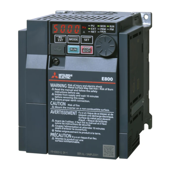
PRE-OPERATION INSTRUCTIONS Unpacking and product confirmation Take the plug-in option out of the package, check the product name, and confirm that the product is as you ordered and intact. This product is a plug-in option made for the FR-E800 series inverters. ... -
Page 9: Component Names
Component names Rear view Front view Pin assignment DG DB SD L.RUN RD L.ERR Connector 1 Connector 2 Refer Symbol Name Description to page Mounting hole Used to fix this product to the inverter by inserting a mounting screw or a spacer. CC-Link communication can be performed with the CC-Link communication CC-Link communication connector connector. -
Page 10: Inverter Option Specifications
Operation status indication LED Item Description L.RUN Lit when refresh data is properly received. Turns off when a data transmission is stopped for a certain period of time. • Lit when a communication error occurs in the own station and flickers when settings of switch, etc. are changed while power is on. L.ERR •... -
Page 11: Cc-Link Version
CC-Link version 1.4.1 CC-Link Ver. 1.10 The conventional CC-Link products, whose inter-station cable lengths have equally been changed to 20 cm or more to improve the inter-station cable length restriction, are defined as CC-Link Ver. 1.10. In comparison, the conventional products are defined as CC-Link Ver. -
Page 12: Cc-Link Ver.2
1.4.2 CC-Link Ver. 2 The FR-A8NC is compatible with CC-Link Ver.2. Master station (CC-Link Ver.1) Master station (CC-Link Ver.2) When using the CC-Link Ver.2 setting with the FR-A8NC, the master station needs to be compatible with the CC-Link Ver.2. For CC-Link Ver.2, double, quadruple and octuple settings can be used to increase the CC-Link Ver.1 CC-Link Ver.1... -
Page 13: Installation
INSTALLATION Pre-installation instructions Check that the inverter's input power and the control circuit power are both OFF. CAUTION • Do not install or remove this product while the inverter power is ON. Doing so may damage the inverter or this product. •... - Page 14 For the FR-E820-0175 (3.7K) or lower, FR-E840-0170 (7.5K) or lower, and FR-E860-0120 (7.5K) or lower Remove the inverter front cover. (Refer to the FR-E800 Instruction Manual (Connection) for instructions to remove the cover.) Use a nipper or the like to cut off the bottom of the front cover for plug-in option. Ensure no burr is left.
- Page 15 Install the hexagon spacers to the inverter. Fit the junction connector, which has been connected to the plug-in option, to the guide of the option connector on the inverter, and insert the junction connector as far as it goes. Fasten this product to the inverter using the two mounting screws through the holes on either side (tightening torque 0.33 to 0.40 N·m).
- Page 16 For the FR-E820-0240(5.5K) or higher Remove the upper front cover and the lower front cover from the inverter. (Refer to the FR-E800 Instruction Manual (Connection) for instructions to remove the covers.) Use a nipper or the like to cut off the dummy cover of the lower front cover in order to install the option small cover. Upper front cover Dummy cover Ensure no burr is left.
- Page 17 Install the hexagon spacers to the inverter. Fit the junction connector, which has been connected to the plug-in option, to the guide of the option connector on the inverter, and insert the junction connector as far as it goes. Fasten this product to the inverter using the two mounting screws through the holes on either side (tightening torque 0.33 to 0.40 N·m).
- Page 18 Install the lower front cover to the inverter. 6. Plug-in option 7. Mounting 4. Hexagon spacer screw 10. Front cover for plug-in option 4. Junction connector 9. Recessed neck screw 7. Mounting screw 4. Straight spacer 10. Option small cover 11.
- Page 19 Insertion positions for screws and spacers Mounting screw Straight spacer Connector L-shaped spacer Mounting screw Insertion positions for screws and spacers INSTALLATION...
- Page 20 NOTE • When the junction connector is installed to the plug-in option, the option is fixed with the hooks of the connector. The junction connector cannot be removed from the plug-in option. • When removing the front cover for plug-in option from the inverter, note that the recessed neck screw cannot be removed from the front cover for plug-in option.
-
Page 21: Setting Of The Terminating Resistor Selection Switch
Setting of the terminating resistor selection switch Always set the terminating resistor selection switch (refer to page 8) or connect the one-touch connector plug with terminating resistor (refer to page 27) to the inverter that is the end station (FR-A8NC) in advance. The following table lists the specifications of the terminating resistor selection switch. -
Page 22: Wiring
Manufacturer FANC-110SBH Kuramo Electric Co., Ltd. CS-110 Dyden Corporation Mitsubishi Electric Engineering FA-CBL200PSBH Co., Ltd. NOTE • For the specifications of the CC-Link dedicated cable, refer to the website of the CC-Link Partner Association. (Website of the CC-Link Partner Association http://www.cc-link.org/) - Page 23 Cable-end treatment Apply the following treatment at wire end of the CC-Link dedicated cable that is inserted to a CC-Link communication one-touch connector plug (accessory). 2. Separate shielding wires from the drain wire. Cut the shielding wires. 1. Cut the sheath. Drain wire Shielding wires 4.
- Page 24 • CC-Link communication one-touch connector plug (as of October 2018) (The product may be changed without notice.) If purchasing a CC-Link communication one-touch connector plug separately, refer to the plugs in the following list. Model Manufacturer A6CON-L5P Mitsubishi Electric Corporation 35505-6000-B0M GF 3M Japan Limited WIRING...
- Page 25 Cable insertion Lift up the back of the plug cover, and insert the cable until it reaches the end. Insert each signal cable into the CC-Link communication one-touch connector plug as shown in the following figure. 5 4 3 2 1 Signal name DA (Blue) DB (White)
- Page 26 Crimping the plug cover Push the plug cover onto the plug with a tool such as pliers. After crimping, check that the plug cover is securely snapped into the plug as shown in the following figure. NOTE • Misaligned latches between the plug cover and the plug may keep the cover lifted. The plug cover is not sufficiently crimped in this condition.
-
Page 27: Connection To The Connector
3.1.2 Connection to the connector Connect the CC-Link dedicated cable to the CC-Link communication connector. CC-Link communication connector CC-Link dedicated cable CAUTION • Take caution not to subject the cables to stress. • After wiring, do not leave wire offcuts in the inverter. Doing so may cause an alarm, failure or malfunction. WIRING... -
Page 28: Unit Replacement While Online
3.1.3 Unit replacement while online Connect an online communication connector to the CC-Link communication connector. The online communication connector enables a unit replacement without interrupting the communication. Always connect the online communication connector to connector 1 (front side) of the CC-Link communication connector. (Do not connect it to connector 2 (back side) of the CC-Link communication connector. - Page 29 Mitsubishi Electric Corporation NOTE • Do not use the online communication connector A6CON-LJ5P (Mitsubishi Electric Corporation) and 35720-L200-B00 AK (3M Japan Limited) for this product. Doing so will cause a failure or breakage of the inverter and the connectors. WIRING...
-
Page 30: System Configuration Example
System configuration example Programmable controller side Load the "RJ61BT11", "QJ61BT11N", "L26CPU-BT", "L26CPU-PBT", "LJ61BT11", "A1SJ61QBT11" or "A1SJ61BT11" type CC-Link system master/local module on the main or extension base unit having the programmable controller CPU used as the master station. Inverter side Mount the plug-in option (FR-A8NC) on the inverter. -
Page 31: Connection Of Several Inverters
Connection of several inverters An inverter can join the link system as a CC-Link remote device station, and such device stations can be controlled and monitored with a user program of a programmable controller. These devices can be useful components of an automated factory. - Page 32 Maximum number of units connected to one master station (CC-Link Ver.2.00) 42 units (when connections are inverter only) If any other units are included, the number of stations occupied depends on the unit and therefore the following conditions must be satisfied: •...
-
Page 33: Inverter Setting
INVERTER SETTING Parameter list The following parameters are used for the plug-in option (FR-A8NC). Set the values according to need. Minimum Initial Refer to Pr. group Name Setting range setting value page increments D000 Operation mode selection 0 to 4, 6, 7 DO0 output selection M410 DO1 output selection... - Page 34 Minimum Initial Refer to Pr. group Name Setting range setting value page increments 0, 1, 12, 14, 18, 100, 112, *1*2 *1*2 CC-Link extended setting N103 114, 118 NET mode operation command source 0, 2, 5, 9999 9999 D012 selection Operation frequency during communication N014 0 to 590 Hz, 9999...
-
Page 35: Operation Mode Setting
Operation mode setting 4.2.1 Operation mode switching and communication startup mode (Pr.79, Pr.340) Operation mode switching conditions Check the following before switching the operation mode. • The inverter is at a stop. • Both the STF and STR signals are off. •... - Page 36 Pr.340 Pr.79 Operation mode at power ON or Operation mode switchover setting setting power restoration Switching among the External, PU, and NET operation mode is 0 (initial External operation mode *1*4 value) enabled. PU operation mode PU operation mode fixed Switching between the External and Net operation mode is External operation mode enabled.
- Page 37 Pr.340 Pr.79 Operation mode at power ON or Operation mode switchover setting setting power restoration Switching between the PU and NET operation mode is enabled. NET operation mode *3*4 PU operation mode Same as when Pr.340 = "0" NET operation mode NET operation mode fixed 3, 4 External/PU combined operation mode...
-
Page 38: Operation At Communication Error Occurrence
Operation at communication error occurrence 4.3.1 Operation selection at communication error occurrence (Pr.500 to Pr.502, Pr.779) You can select operations at communication error occurrences by setting Pr.500 to Pr.502, Pr.779 under network operation. Waiting time for the communication line error output after a communication error Waiting time for the communication error output after a communication line error occurrence can be set. - Page 39 Displaying and clearing the communication error count The cumulative count of communication error occurrences can be displayed. Write "0" to clear this cumulative count. Minimum setting Name Setting range Initial value increments Communication error occurrence count display Normal Error Normal Error Count timing depending on...
- Page 40 About setting • Operation at an error occurrence Fault description Pr.502 setting Operation Indication Fault output Communication line Continued Normal Not output Output shutoff "E. 1" Provided Output to decelerate and stop 1, 2 "E. 1" after stop Provided after stop Communication option the motor Operation continued at the set...
- Page 41 • Operation at error removal Fault description Pr.502 setting Operation Indication Fault output Output stop status continues. "E.OP1" kept Kept provided Communication line Restart Normal Not output Normal Output stop status continues. "E. 1" kept Kept provided Communication option 1, 2 itself Operation continued at the set "CF"...
- Page 42 NOTE • The protective function [E.OP1 (fault data: HA1)] is activated at error occurrences on the communication line. The protective function [E.1 (fault data: HF1)] is activated at error occurrences in the communication circuit inside the option. • Fault output indicates the fault (ALM) signal and fault bit output. •...
-
Page 43: Fault And Measures
4.3.2 Fault and measures Inverter operation in each operation mode at error occurrences Operation mode Location Status Network operation External operation PU operation Inverter operation Output shutoff Output shutoff Output shutoff Inverter Data communication Continued Continued Continued Inverter operation Continued Continued Output shutoff... -
Page 44: Inverter Reset
Inverter reset Operation conditions of inverter reset Which resetting method is allowed or not allowed in each operation mode is described below. Operation mode Resetting method Network External operation operation operation Allowed Disallowed Disallowed Inverter reset (Refer to page 73.) Reset from the Pr.349 = 0... - Page 45 Error reset operation selection at inverter fault An error reset command from communication option can be invalid in the External operation mode or PU operation mode. Use RY1A for an error reset command from network. (Refer to page 61.) Initial Name Setting range...
-
Page 46: Cc-Link Function Setting
CC-Link function setting 4.5.1 Station number setting (Pr.542) Use Pr.542 Communication station number (CC-Link) to set station number of the inverter. Set this parameter within the range of 1 to 64. Name Initial value Setting range Communication station number (CC-Link) 1 to 64 NOTE •... - Page 47 NOTE • Set consecutive numbers for the station numbers. (Do not skip a number in sequence like "station number 1 - station number 2- station number 4".) The station number does not have to match with the physical connection sequence. (There is no problem with having the physical connection sequence like "station number 1 - station number 3 - station number 4 - station number 2".) •...
-
Page 48: Baud Rate Setting (Pr.543)
4.5.2 Baud rate setting (Pr.543) Set the transmission speed. (Refer to the manual for the CC-Link master module for details of transmission speed.) Name Initial value Setting range Transmission speed 156 kbps 625 kbps Baud rate selection (CC-Link) 2.5 Mbps 5 Mbps 10 Mbps NOTE... - Page 49 Speed setting using Pr.541 Sign Setting range Actual frequency command Pr.37 and Pr.53 setting Not used 0 to 59000 0 to 590.00 Hz Not used -32768 to 32767 With -327.68 to 327.67 Hz (two's complement) Not used 0 to 65535 It depends on Pr.37, Pr.53 With -32768 to 32767...
-
Page 50: Function Overview
FUNCTION OVERVIEW Function block diagram Using function blocks, this section explains I/O data transfer to/from an inverter in CC-Link: • Link refresh is continuously executed between the master station and inverter in the CC-Link system at intervals of 1.1 ms to 141 ms (per station). -
Page 51: Output From The Inverter To The Network
Output from the inverter to the network Main items which can be output from the inverter to the master and their descriptions are explained below. Item Description Refer to page Inverter status monitor The output terminal status of the inverter can be monitored. Output frequency monitor The output frequency can be monitored. -
Page 52: Input To The Inverter From The Network
Input to the inverter from the network Main items which can be commanded from the master to the inverter and their descriptions are explained below. Item Description Refer to page Forward rotation command Give the forward rotation command. Reverse rotation command Give the reverse rotation command. -
Page 53: O Signal List
I/O SIGNAL LIST CC-Link extended setting (Pr.544) Remote register function can be extended. Initial Setting CC-Link Name Description Refer to page value range Ver. Occupies one station (FR-A5NC compatible) Occupies one station Occupies one station double Occupies one station quadruple CC-Link extended Occupies one station octuple setting... -
Page 54: I/O Signal List
I/O signal list 6.2.1 I/O signal when CC-Link Ver.1 one station (FR-A5NC compatible) is occupied (Pr.544 = 0) Remote I/O (32 points) Refer Refer Signal Signal Device no. Device no. page page RYn0 RXn0 Forward running Forward rotation command RYn1 RXn1 Reverse running... - Page 55 Refer Refer Signal Signal Device no. Device no. page page RYnD Frequency setting command (RAM) RXnD Frequency setting completion (RAM) Frequency setting command (RAM, Frequency setting completion (RAM, RYnE RXnE EEPROM) EEPROM) RYnF Instruction code execution request RXnF Instruction code execution completion RX(n+1)0 Reserved ─...
- Page 56 Output signal can be assigned using Pr.313 to Pr.315. The settings of Pr.313 to Pr.315 are the same as those of Pr.190 to Pr.196 (output terminal function selection). For the details of Pr.190 to Pr.196, refer to the FR-E800 Instruction Manual (Function). "n"...
-
Page 57: I/O Signal When Cc-Link Ver.1 One Station Is Occupied (Pr.544 = 1)
6.2.2 I/O signal when CC-Link Ver.1 one station is occupied (Pr.544 = 1) Remote I/O (32 points) Same as when Pr.544 = 0 (Refer to page Remote register Description Refer Description Refer Address Address Upper 8 bits Lower 8 bits Upper 8 bits Lower 8 bits page... -
Page 58: I/O Signal When Cc-Link Ver.2 Double Setting Is Selected (Pr.544 = 12)
6.2.3 I/O signal when CC-Link Ver.2 double setting is selected (Pr.544 = 12) Remote I/O (32 points) Same as when Pr.544 = 0 (Refer to page Remote register Description Refer Description Refer Address Address Upper 8 bits Lower 8 bits Upper 8 bits Lower 8 bits page... -
Page 59: I/O Signal When Cc-Link Ver.2 Quadruple Setting Is Selected (Pr.544 = 14)
6.2.4 I/O signal when CC-Link Ver.2 quadruple setting is selected (Pr.544 = 14) Remote I/O (32 points (64 points occupied)) Same as when Pr.544 = 0 (Refer to page Remote register Description Refer Description Refer Address Address Upper 8 bits Lower 8 bits Upper 8 bits Lower 8 bits... -
Page 60: I/O Signal When Cc-Link Ver.2 Octuple Setting Is Selected (Pr.544 = 18)
6.2.5 I/O signal when CC-Link Ver.2 octuple setting is selected (Pr.544 = 18) Remote I/O (32 points (128 points occupied)) Same as when Pr.544 = 0 (Refer to page Remote register Description Refer Description Refer Address Address Upper 8 bits Lower 8 bits Upper 8 bits Lower 8 bits... - Page 61 Description Refer Description Refer Address Address Upper 8 bits Lower 8 bits Upper 8 bits Lower 8 bits page page Link parameter RWwn+12 Instruction code RWrn+12 Reply code extended setting RWwn+13 Write data RWrn+13 Read data Link parameter RWwn+14 Instruction code RWrn+14 Reply code extended setting...
-
Page 62: Details Of Input And Output Signals
DETAILS OF INPUT AND OUTPUT SIGNALS The following device No. are those for station 1. For stations 2 and later, the device No. are different. (Refer to the master module manual for correspondence between the device No. and station number) Details of remote input and output signals 7.1.1 Output signals (master module to inverter (FR-A8NC)) - Page 63 Device no. Signal Description The function assigned to terminal RES is activated. Reset (RES terminal function) When "1" is set in RYC, the monitored value is set in the remote register RWr0, 1, 4 Monitor command to 7, and "1" is set in the monitoring (RXC). While "1" is set in RYC, the monitored data is always updated.
- Page 64 controlled via network. For details of Pr.180 to Pr.189, Pr.338, and Pr.339, refer to the FR-E800 Instruction Manual (Function). The signals are fixed. They cannot be changed using parameters. While "1" is set in the frequency setting command (RYD), the set frequency (RWw1) is always applied. If "1"...
-
Page 65: Input Signals (Inverter (Fr-A8Nc) To Master Module)
7.1.2 Input signals (inverter (FR-A8NC) to master module) The input signals to the master module are indicated. (Output signals from inverter) Device no. Signal Description 0: Other than forward running (during stop or reverse rotation) Forward running 1: Forward running 0: Other than reverse running (during stop or forward rotation) Reverse running 1: Reverse running... - Page 66 Device no. Signal Description After "1" is set in the frequency setting command/torque command (RYE) and the frequency setting command/torque command is written to the inverter RAM and EEPROM, "1" is set in this signal. When "0" is set in the frequency setting command/ Frequency setting completion/torque torque command (RYE), "0"...
-
Page 67: Details Of Remote Register
Details of remote register 7.2.1 Remote register (master module to inverter (FR-A8NC)) Remote register definition Device no. Signal Description Set the monitor code to be referenced (Refer to page 77). When "1" is set in RYC, data of RWw0 Monitor code 1, 2 specified monitored items will be stored in RWr0, RWr1. - Page 68 Device no. Signal Description Set how many fault records in past to be read. Back to ten fault records in past can be read (lower 8 bits is H00). RWw8 Fault record No. Upper 8 bits: H00 (latest fault) to H09 (ten faults in past) When H0A to HFF is set to the upper 8 bits, the fault record becomes an undetermined value.
- Page 69 Setting range: -327.68 Hz to 327.67 Hz (-327.68 to 327.67) 0.01 Hz increments For details refer to page When Pr.128 = "50, 51, 60, 61", they are valid. If the data outside the range is set, the previous setting is retained. For the details of Pr.128, refer to the FR-E800 Instruction Manual (Function).
-
Page 70: Remote Register (Inverter (Fr-A8Nc) To Master Module)
7.2.2 Remote register (inverter (FR-A8NC) to master module) Remote register definition Device no. Signal Description When "1" is set in RYC, the specified monitored data is set to the lower 8 bits of the monitor code RWr0 First monitor value (RWw0). - Page 71 Device no. Signal Description Fault record RWrC Energization time of the fault record No. specified in RWw8 is stored. (energization time) When "1" is set in RYF, the reply codes corresponding to the instruction code RWw10, 12, 14, 16, Reply code and 18 are set.
- Page 72 Data Item Alarm definition Remarks No error (normal completion of instruction code Normal execution) Parameter write was attempted during operation Write mode error other than a stop in the network operation mode. Reply code 1 Frequency command / torque command / The value outside the range is set.
- Page 73 The contents of the reply code 1 are changed when torque commands are given or the torque is limited (when Pr.544 = "14 or 18"). The upper 4 bits of the reply code 1 are used as the reply code to the torque command / torque limit, and the lower 4 bits are used as the reply code to the frequency command.
-
Page 74: Instruction Codes
7.2.3 Instruction codes Instruction code definition Set the instruction code using a remote register (RWw) (Refer to page 66.) The definition read by the instruction code is stored in the remote register (RWr). (Refer to page 69.) Read/ Instruction Item Description write... - Page 75 Read/ Instruction Item Description write code H0000 to HFFFF: Two fault records per code. b8 b7 For instruction code H74, read data H30A0 Second latest fault Latest fault b8 b7 Fourth latest fault Third latest fault 1 0 0 0 0 Sixth latest fault Fifth latest fault Second fault...
- Page 76 Read/ Instruction Item Description write code • Refer to the instruction codes in the FR-E800 Instruction Manual (Function) to read/ write parameters as required. Read H00 to H63 Write to Pr.77 and Pr.79 is disabled. When setting Pr.100 and later, set link parameter extended setting. •...
- Page 77 Read/ Instruction Item Description write code Read or write of bias and gain parameters. For the details of setting values, refer to the Read calibration parameter list of the FR-E800 Instruction Manual (Function). Second parameter H00: Frequency changing H01: Analog value set in parameters Write H02: Analog value input from the terminal When "100"...
-
Page 78: Monitor Codes
7.2.4 Monitor codes Information about the inverter can be monitored by setting the special monitor selection No. of the instruction code and monitor code using the remote registers, RWw0 and RWw4 to 7. • For the monitor code (RWw0), select the first monitor description (RWr0) from the lower 8 bits and the second monitor description (RWr1) from the upper 8 bits. -
Page 79: Torque Command / Torque Limit By Cc-Link Communication
Torque command / torque limit by CC-Link communication Torque commands can be given or the torque can be limited by CC-Link communication under Real sensorless vector control, or PM sensorless vector control. The value is used to limit the torque during speed control, and to give a torque command during torque control. - Page 80 When a negative value is set as the torque limit, the torque is limited by the absolute value. Available only when the FR-A8AX is installed. For details, refer to the FR-A8AX E kit Instruction Manual. List of I/O devices whose function is changed according to the parameter settings and the control method Real sensorless vector control / V/F control /...
- Page 81 Torque command setting method and parameter for speed limit Parameter Pr.804 Pr.544 Torque command setting method for speed setting setting (Any method below can be chosen) limit • Set the torque command value in RWwn+1, and "1" in RYD or RYE. •...
-
Page 82: Programming Examples
PROGRAMMING EXAMPLES This chapter provides programming examples which control the inverter with sequence programs. Refer to Item Program example page Reading the inverter status Reading the inverter status from the buffer memory of the master station Setting the operation mode Selecting the network operation mode Setting the operation commands Commanding the forward rotation and middle speed signals... - Page 83 Network parameter setting of the master station Network parameters are set as below. Item Setting conditions Item Setting conditions Start I/O No. 0000 Remote register (RWw) W100 Data link alarm station Input clear Special relay (SB) Operation setting settings Setting at CPU stop Refresh Special resister (SW)
- Page 84 • The relation between the device of the programmable controller CPU • The relation between the device of the programmable controller CPU and remote I/O (RX, RY) of the remote device station is as follows: and remote register (RWw, RWr) of the remote device station is as The devices used actually are indicated in shaded regions.
-
Page 85: Program Example For Reading The Inverter Status
Program example for reading the inverter status The following program turns on Y00 of the output unit when station 1 inverter is running SW80.0 Check the data link status of the station 1 X1002 Turn on the output unit (Y00) Inverter running (RX02) X100F X1000... -
Page 86: Program Example For Setting The Operation Mode
Program example for setting the operation mode The following explains a program to write various data to the inverter. The following explains a program to change the operation mode of station 1 inverter to network operation. • Operation mode write code: HFB (hexadecimal) •... -
Page 87: Program Example For Setting The Operation Commands
Program example for setting the operation commands The following program gives a forward command and middle speed command to station 1 inverter SW80.0 Check the data link status of the station 1 Y1000 Forward rotation command (RY00) Y1003 Middle speed operation command (RY03) Y100F Y1000 RY0F to RY00... -
Page 88: Program Example For Monitoring The Output Frequency
Program example for monitoring the output frequency The following explains a program to read monitor functions of the inverter. The following program reads the output frequency of station 1 inverter to D1. Output frequency read code: H0001 (hexadecimal) Refer to page 77 for the monitor codes. -
Page 89: Program Example For Parameter Reading
Program example for parameter reading The following program reads Pr.7 Acceleration time of station 1 inverter to D1. • Pr.7 Acceleration time reading instruction code: H07 (hexadecimal) • For the instruction codes of parameters, refer to the FR-E800 Instruction Manual (Function). •... -
Page 90: Program Example For Parameter Writing
Program example for parameter writing The following program changes the setting of Pr.7 Acceleration time of station 1 inverter to 3.0 s. • Acceleration time writing instruction code: H87 (hexadecimal) • Acceleration time set data: K30 (decimal) For the instruction codes of parameters, refer to the FR-E800 Instruction Manual (Function). The reply code at the time of instruction code execution is set to D2. -
Page 91: Program Example For Setting The Running Frequency
Program example for setting the running frequency • The following program example changes the running frequency of station 1 inverter to 50.00 Hz Set frequency: K5000 decimal The reply code at the time of instruction code execution is set to D2. (Refer to page SW80.0 Check the data link status of the station 1... - Page 92 • To continuously change the running frequency from the programmable controller When the frequency (speed) setting completion (example: X100D) switches on, make sure that the reply code in the remote register is H0000 and change the set data (example: W101) continuously. •...
-
Page 93: Program Example For Fault Record Reading
Program example for fault record reading The following program reads fault records of station 1 inverter to D1. • Fault record No. 1, No. 2 reading instruction code: H74 (hexadecimal) For the error codes, refer to the FR-E800 Instruction Manual (Maintenance). The reply code at the time of instruction code execution is set to D2. -
Page 94: Program Example For Resetting The Inverter At Inverter Error
Program example for resetting the inverter at inverter error The following is a program example for resetting station 1 inverter. SW80.0 Check the data link status of the station 1 M0 X101A X20 Turn on the error reset request flag (RY1A) Y101A Turn off the error reset request flag (RY1A) Error status flag... -
Page 95: 8.10 Instructions
8.10 Instructions Programming instructions • Since the buffer memory data of the master station is kept transferred (refreshed) to/from the inverters, the TO instruction need not be executed every scan in response to data write or read requests. The execution of the TO instruction every scan does not pose any problem. - Page 96 Troubleshooting Description Check point Check that the option unit (FR-A8NC) and CC-Link dedicated cables are fitted properly. (Check for contact fault, break in the cable, etc.) Pr.542 Communication station number (CC-Link) setting switches are set to the correct positions. Operation mode does not switch to the (Check that the station number matches the program, the station numbers are not repeated, and network operation mode...
-
Page 97: How To Check For Error Using The Leds
HOW TO CHECK FOR ERROR USING THE LEDS When one inverter is connected The following diagram shows the system configuration with one inverter. The diagram indicates how the cause of the fault can be checked with the LED status of the inverter communication option (FR-A8NC). (In this example, assume SW, M/S, and PRM LEDs of the master module are OFF (master module is in normal operation).) Master Power... - Page 98 LED status Cause L.RUN L.ERR ● ● Normal communication is made but CRC error has occurred due to noise. ● ● ○ Normal communication ● ● ○ Hardware fault ● ● ○ ○...
-
Page 99: When Two Or More Inverters Are Connected
When two or more inverters are connected The following system configuration shows how the cause of a fault can be checked with the LED status of the inverter communication option (FR-A8NC) and countermeasures for the fault. (In this example, assume SW, M/S, and PRM LEDs of the master module are OFF (master module is in normal operation).) Power Master Station 1... - Page 100 LED status Inverters (FR-A8NC) Cause Corrective action Master unit Station 1 Station 2 Station 3 RUN● RUN● RUN● Since the L.RUN LEDs of the FR-A8NC on L.RUN● L.RUN○ L.RUN○ station 2 and later are off, the CC-Link Referring to the LED "on" SD●...
-
Page 101: Communication Stops During Operation
Communication stops during operation • Check that the option unit (FR-A8NC) and CC-Link dedicated cables are fitted properly. (Check for contact fault, break in the cable, etc.) • Check that the programmable controller program is executed properly. • Check that data communication has not stopped due to an instantaneous power failure, etc. LED status Inverters (FR-A8NC) Cause... - Page 102 LED status Inverters (FR-A8NC) Cause Corrective action Master unit Station 1 Station 2 Station 3 RUN● RUN● RUN● Since the L.ERR LED of the FR-A8NC on L.RUN● L.RUN● L.RUN● station 2 is on, the FR-A8NC itself on station 1 Securely earth (ground) each SD●...
-
Page 103: Appendix
CE marking. • The authorized representative in the EU The authorized representative in the EU is shown below. Name: Mitsubishi Electric Europe B.V. Address: Mitsubishi-Electric-Platz 1, 40882 Ratingen, Germany EMC Directive We declare that this product conforms with the EMC Directive when installed in a compatible inverter, and affix the CE marking on the packaging plate. -
Page 104: Appendix 2 Instructions For Eac
Year, and the Month is indicated by 1 to 9, X (October), Y (November), or Z (December). • Authorized sales representative (importer) in the CU area The authorized sales representative (importer) in the CU area is shown below. Name: Mitsubishi Electric (Russia) LLC Address: 52, bld 1 Kosmodamianskaya Nab 115054, Moscow, Russia Phone: +7 (495) 721-2070... -
Page 105: Appendix 3 Restricted Use Of Hazardous Substances In Electronic And Electrical Products
Appendix 3 Restricted Use of Hazardous Substances in Electronic and Electrical Products The mark of restricted use of hazardous substances in electronic and electrical products is applied to the product as follows based on the “Management Methods for the Restriction of the Use of Hazardous Substances in Electrical and Electronic Products”... -
Page 106: Appendix 4 Referenced Standard (Requirement Of Chinese Standardized Law)
Appendix 4 Referenced Standard (Requirement of Chinese standardized law) This Product is designed and manufactured accordance with following Chinese standards. EMC: GB/T 12668.3 APPENDIX... - Page 107 REVISIONS *The manual number is given on the bottom left of the back cover. Revision *Manual number Revision date Dec. 2019 IB(NA)-0600886ENG-A First edition IB(NA)-0600886ENG-A...
- Page 108 INVERTER HEAD OFFICE: TOKYO BUILDING 2-7-3, MARUNOUCHI, CHIYODA-KU, TOKYO 100-8310, JAPAN IB(NA)-0600886ENG-A(1912) MEE Printed in Japan Specifications subject to change without notice.