Siemens SENTRON 7KN POWERCENTER 3000 Manual
Iot data platforms
Hide thumbs
Also See for SENTRON 7KN POWERCENTER 3000:
- Manual (102 pages) ,
- Quick install manual (2 pages) ,
- Manual (112 pages)
Table of Contents
Table of Contents

Related Manuals for Siemens SENTRON 7KN POWERCENTER 3000


Summary of Contents for Siemens SENTRON 7KN POWERCENTER 3000
- Page 3 Introduction Safety information SENTRON Description Installing, connecting, commissioning IoT data platforms 7KN POWERCENTER 3000 Functions Application examples Equipment Manual Service and maintenance FAQs Technical data Dimensional drawings Appendix Technical support V1.2 07/2020 L1V30579222003-03...
- Page 4 Note the following: WARNING Siemens products may only be used for the applications described in the catalog and in the relevant technical documentation. If products and components from other manufacturers are used, these must be recommended or approved by Siemens. Proper transport, storage, installation, assembly, commissioning, operation and maintenance are required to ensure that the products operate safely and without any problems.
-
Page 5: Table Of Contents
Table of contents Introduction ............................7 Reference documents ......................7 Advanced training courses ....................8 Technical Support ........................ 8 Safety information ..........................9 General safety information ....................9 Security information ......................11 Information on use ......................11 Open Source Software ....................... 12 Description ............................ - Page 6 Table of contents Interfaces of the 7KN POWERCENTER 3000 ................. 35 4.6.1 Internal Ethernet interface for the smart assembly network ..........35 4.6.1.1 Performance features of the smart assembly interface ............35 4.6.2 External Ethernet interface with the intranet ..............37 4.6.2.1 Performance features of the external Ethernet interface .............
- Page 7 Table of contents Modbus devices ......................... 81 5.9.1 Creating and configuring a Modbus device ................. 82 5.9.1.1 Example for addressing a data point ................... 84 5.9.1.2 Supported data formats ..................... 85 5.9.2 Integrating the Modbus device into the communication ............. 86 5.9.3 Displaying a Modbus device with powerconfig ..............
- Page 8 Table of contents FAQs ..............................119 No firmware update via powerconfig ................119 Version management between powerconfig and 7KN POWERCENTER 3000 ...... 119 Special aspects of powerconfig V3.15 ................120 Modifications in smart assembly networks ............... 121 Technical data ........................... 123 General technical data .....................
-
Page 9: Introduction
The following editions of the manual have been published so far: Edition Comment 08/2019 First edition 03/2020 Version 02 Reference documents You can find further details in the following documents: Title Article number Quick Installation Guide 7KN POWERCENTER 3000 L1V30579222002 (https://support.industry.siemens.com/cs/ww/en/view/109766001) 7KN POWERCENTER 3000 Equipment Manual, 07/2020, L1V30579222003-03... -
Page 10: Advanced Training Courses
1.2 Advanced training courses Advanced training courses Find out about training courses on offer on the following link. Training for Industry (https://www.siemens.de/sitrain-lowvoltage) Here you can choose from: • Web-based training courses (online, informative, free) • Classroom training courses (course attendance, comprehensive, subject to fee) You also have the possibility of compiling your own training portfolio via Learning paths. -
Page 11: Safety Information
Safety information General safety information WARNING The safety of a system in which the device is integrated is the responsibility of those who install the system. There is danger of a malfunction resulting in death of serious injury. • Ensure only qualified personnel perform work. WARNING Lethal voltage when the control cabinet is open. - Page 12 Safety information 2.1 General safety information Battery WARNING Danger of explosion and danger of release of harmful substances Improper handling of lithium batteries can result in explosion of the batteries. Explosion of the batteries and the resulting release of harmful substances can result in serious injury.
-
Page 13: Security Information
To keep up to date with all the latest product updates, subscribe to the Siemens Industrial Security RSS Feed at (https://www.siemens.com/industrialsecurity). Information on use... -
Page 14: Open Source Software
Product or any OSS components contained in it if they are modified or used in any manner not specified by SIEMENS. The license conditions may contain disclaimers that apply between you and the respective licensor. -
Page 15: Description
Description Product description Overview The 7KN Powercenter 3000 has high industrial functionality. • Compact dimensions • Highly robust 7KN POWERCENTER 3000 Equipment Manual, 07/2020, L1V30579222003-03... -
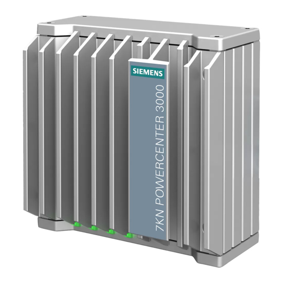
Page 16: Design Of The Devices
Description 3.2 Design of the devices Design of the devices Interfaces and connections ① Ground connection ② Connection for the 24 V DC power supply ③ 2 x USB 3.0 port, high current ④ Not used ⑤ 2 x RJ45 Ethernet port X1P1 and X2P1 for 10/100/1000 Mbps ⑥... -
Page 17: Operating Displays Of The Devices
Description 3.2 Design of the devices 3.2.1 Operating displays of the devices LED name Status Description PC ON/WD No voltage Green BIOS active Flashing green / yellow (4 Hz) Power ON self-test Yellow Idle state / shutdown Flashing red (4 Hz) Fault monitoring has triggered L1 RUN/STOP Not used... -
Page 18: Accessories
Upright mounting for the 6AG4021-0AA20-0AA3 7KN Powercenter 3000 Upright mounting on DIN rails 6AG4021-0AA20-0AA5 Lithium battery A5E44491494 You will find further information on the Internet at: • Service & Support (https://support.industry.siemens.com/cs/ww/en/) Hardware description 3.4.1 Data interfaces Interface overview Interface Description X1P1... - Page 19 Description 3.4 Hardware description Ethernet interface Short code Meaning LED 1 Off: 10 Mbps Lights up green: 100 Mbps Lights up yellow: 1000 Mbps LED 2 Lights up yellow: Connection established Flashing: Activity 7KN POWERCENTER 3000 Equipment Manual, 07/2020, L1V30579222003-03...
- Page 20 Description 3.4 Hardware description 7KN POWERCENTER 3000 Equipment Manual, 07/2020, L1V30579222003-03...
-
Page 21: Installing, Connecting, Commissioning
Installing, connecting, commissioning Preparing installation 4.1.1 Checking delivery Procedure 1. When you receive the delivery, check the packaging for visible damage in transit. 2. If you discover damage in transit, lodge a complaint with the carrier responsible. Have the carrier confirm the damage in transit immediately. 3. - Page 22 Installing, connecting, commissioning 4.1 Preparing installation NOTICE Damaged device • Ensure that the damaged device is not installed and commissioned. • Label the damaged device and keep it locked away. • Send the device for repair immediately. NOTICE Damage due to condensation If the device has been exposed to low temperatures or extreme temperature fluctuations during transportation, e.g.
-
Page 23: Identification Data Of The Device
Installing, connecting, commissioning 4.1 Preparing installation 4.1.2 Identification data of the device The identification data can be used to uniquely identify the device in case of repair or theft. Enter the identification data of your rating plate in the following table. Order number 7KN1310-0MC00-0AA8 Production version (FS) -
Page 24: Permissible Mounting Positions
Installing, connecting, commissioning 4.1 Preparing installation 4.1.3 Permissible mounting positions The following mounting positions are permitted: • Upright mounting • Upright mounting on DIN rails • Wall mounting • Mounting on DIN rails Pay attention to the permissible temperature range for operation depending on the mounting position as stated in Technical data (Page 123). -
Page 25: Upright Mounting
Installing, connecting, commissioning 4.1 Preparing installation 4.1.3.1 Upright mounting The upright mounting is suitable for vertical mounting of the device. The mounting bracket provided for this permits space-saving installation with DIN rail and wall mounting. Requirements • Mounting bracket Note Use only the screws supplied to mount the mounting bracket. -
Page 26: Upright Mounting On Din Rails
Installing, connecting, commissioning 4.1 Preparing installation 4.1.3.2 Upright mounting on DIN rails Upright mounting on DIN rails is suitable for vertical mounting of the device. The mounting bracket for this permits space-saving installation with wall mounting. Requirements • Mounting bracket Note Use only the screws supplied to mount the mounting bracket. -
Page 27: Wall Mounting
Installing, connecting, commissioning 4.1 Preparing installation 4.1.3.3 Wall mounting The wall mounting is suitable for horizontal mounting of the device. Requirements • Mounting bracket Note Use only the screws supplied to mount the mounting bracket. Longer screws can damage the interior of the device •... -
Page 28: Mounting On Din Rails
Mounting on DIN rails The standard rail mounting is suitable for horizontal and vertical mounting of the device. Requirements • A SIEMENS 35-mm DIN rail TH35-15 in accordance with EN 60715:2001 The DIN rail is mounted. • A DIN rail clip Note Use only the screws supplied to mount the DIN rail clip. -
Page 29: Mounting The Device
Installing, connecting, commissioning 4.2 Mounting the device Mounting the device 4.2.1 Mounting instructions Note the following: • The device is only approved for operation in closed rooms. Mounting tips for power distribution boards: • Maintain the largest possible clearance from the main circuit, e.g. mounting in the cross- wiring compartment. -
Page 30: Connecting The Device
Installing, connecting, commissioning 4.3 Connecting the device Connecting the device 4.3.1 Instructions for connection WARNING Danger of fire and danger due to electric shock The ON/OFF switch does not disconnect the device from the power supply. Danger of electric shock on incorrect opening of the device and on a device nonconformance. If the device or the connecting cables are damaged, there is also a danger of fire. - Page 31 Installing, connecting, commissioning 4.3 Connecting the device NOTICE Fault due to peripheral devices/USB V3.0 devices Connection of peripheral devices can result in faults on the device. This can result in personal injury and damage to the machine or plant. Note the following when connecting peripheral devices/USB V3.0 devices: •...
-
Page 32: Connecting The Ground Conductor
Installing, connecting, commissioning 4.3 Connecting the device 4.3.2 Connecting the ground conductor A connected ground conductor conducts potentially hazardous electrical charges to the metal enclosure. The current flowing through the ground conductor in such a case trips the line- side fusing device that disconnects the device from the power supply. Moreover, the ground conductor improves the conduction of interference that is transmitted via external power supply cables, signal cables, or cables to peripheral devices. -
Page 33: Connecting The Power Supply
Installing, connecting, commissioning 4.3 Connecting the device Procedure 1. Connect the cable lug to the ground conductor. 2. Connect the cable lug with the M4 thread firmly to the ground connection on the device (see marked position). 3. Connect the ground conductor to the ground connection for the cabinet or the equipment in which the device is installed. - Page 34 Installing, connecting, commissioning 4.3 Connecting the device Note The 24 VDC power supply must meet the voltage requirements specified in Technical data (Page 123). Requirements • The ground conductor has been connected. • You are using the terminal provided. • A two-wire cable with a conductor cross-section for the 24 V DC connection of 0.75 mm to 2.5 mm (18 - 12 AWG).
-
Page 35: Connecting The Device To Networks
Installing, connecting, commissioning 4.4 Connecting the device to networks Connecting the device to networks For integration into existing or planned system environments and networks, the following options are available. Ethernet You can use the integrated Ethernet interfaces (10/100/1000 Mbps) for communication with the devices and applications stated in Application examples (Page 89). -
Page 36: Switching The Device On/Off
Installing, connecting, commissioning 4.5 Commissioning a device 4.5.2 Switching the device on/off Procedure - switching the device on The device starts as soon as 24 VDC is applied. Note The LED "PC ON/WD" lights up green. You will find more information on the LEDs in Operating displays of the devices (Page 15). Procedure - switching the device off 7KN Powercenter 3000 can be switched off with the ON/OFF switch (see Design of the devices (Page 14)) using a narrow object, e.g. -
Page 37: Interfaces Of The 7Kn Powercenter 3000
• powerconfig (optional) • Web user interface, e.g. HMI Panel. The default IP address on X2P1 is: 192.168.1.2 You will find further devices in the Download information (https://support.industry.siemens.com/cs/ww/en/view/109762951) of the firmware update. 4.6.1.1 Performance features of the smart assembly interface •... - Page 38 Installing, connecting, commissioning 4.6 Interfaces of the 7KN POWERCENTER 3000 • Communication over Modbus TCP • Interface with web browsers. Various browser types are supported. Typical devices of a smart assembly network The interface must be multiplied for the individual devices using an industrial-type Ethernet switch, e.g.
-
Page 39: External Ethernet Interface With The Intranet
• Interface with web browsers. Various browser types are supported. • Interface with MindSphere, the Siemens operating system for the Internet of Things (IoT). • Support of application on other cloud systems. -
Page 40: Security Features
Installing, connecting, commissioning 4.7 Security features Security features The security features of a central communication device, such as the 7KN Powercenter 3000, provide protection against unauthorized access and require specific attention during use. In the same way that a lock on a door provides protection and is also an obstacle that can be overcome with the matching key. -
Page 41: Security Features Of The 7Kn Powercenter 3000
Security features of the 7KN POWERCENTER 3000. • Signed firmware: The 7KN Powercenter 3000 can only be operated with firmware signed by SIEMENS. This makes operation with corrupted or manipulated firmware impossible. Downgrading to firmware that may be faulty is not possible either. -
Page 42: Further Recommended Security Measures
4.7 Security features • Continuous vulnerability management: For 7KN Powercenter 3000 as for many other Siemens devices, continuous vulnerability management is set up. This means that if security vulnerabilities are found in individual program sections, they are published via Siemens ProductCERT and rectified as soon as possible in a firmware update. - Page 43 Installing, connecting, commissioning 4.7 Security features • VPN: VPN is the abbreviation for "virtual private network" and refers to a logically self- contained network. A VPN connects a few known network nodes via encrypted communication via a larger, potentially insecure network, e.g. Internet. If the web user interface of the 7KN Powercenter 3000 can be accessed via the Internet, we strongly recommend establishing a VPN connection between the web client (device on which the web browser is running) and the router.
-
Page 45: Functions
Functions As energy, operating and investment costs steadily increase, it is important for operators to keep track of actual power consumption and the status of the power distribution board. 7KN Powercenter 3000 provides numerous important functions for this. For greater clarity, these functions can be assigned to one or several types of application: Function overview of the 7KN POWERCENTER 3000 Digital documentation •... - Page 46 Functions 7KN Powercenter 3000 provides a secure and universal communication interface for all stated functions. The external and internal communication interfaces have been deliberately separated to ensure the security and functional independence. The device types mentioned in "Internal Ethernet interface for the smart assembly network (Page 35)"...
-
Page 47: Commissioning With Powerconfig
Functions 5.1 Commissioning with powerconfig Commissioning with powerconfig 7KN Powercenter 3000 is commissioned like the other communication-capable SENTRON devices with powerconfig. In principle, commissioning is possible with powerconfig. You will find further information in FAQs (Page 119). 5.1.1 First commissioning On first commissioning, powerconfig is connected to the internal network (X2 P1, default IP address: 192.168.1.2) of the smart assembly. -
Page 48: Web User Interface
Functions 5.2 Web user interface Web user interface Note The web user interface must only be used in compliance with Security features (Page 38). 7KN Powercenter 3000 provides web user interfaces for following display options: • on a PC • on a tablet •... -
Page 49: Contents Of The Web User Interface
Functions 5.2 Web user interface 5.2.1 Contents of the Web user interface The essential elements of the Web user interface are explained below. An overview of the entire application, e.g. of a smart switchgear assembly, is automatically created from the project (*.splx). The standard view can be further adapted to the particular requirements. -
Page 50: Toolbar
Functions 5.2 Web user interface 5.2.1.1 Toolbar Depending on the area or device selected in the navigation area, a toolbar is displayed. Area-specific or device-specific views are selected via the corresponding menu items. • The bell icon ① displays the event messages since the last selection. By clicking on the icon, the messages are displayed in the project. -
Page 51: Widgets
Functions 5.2 Web user interface 5.2.1.2 Widgets Widgets are display elements that can be added, modified and deleted. Their size and position can be modified with the following symbol. The layout can be modified by movement of the widgets. The changes are retained after the page has been exited. - Page 52 Functions 5.2 Web user interface Messages are available both for devices and in an overview. By clicking a message, details are made visible, if available. 7KN POWERCENTER 3000 Equipment Manual, 07/2020, L1V30579222003-03...
-
Page 53: Settings Via The Web User Interface
Functions 5.2 Web user interface 5.2.2 Settings via the web user interface The 7KN Powercenter 3000 is the first SENTRON device to provide a way of making important parameter settings via the web user interface, alongside the option provided via powerconfig. -
Page 54: Write Protection In The Web User Interface
Functions 5.2 Web user interface • Settings relating to the current application are grouped together under "General". Services can be activated or deliberately deactivated, for example, for security reasons. • Related settings of the communication interfaces are to be found in "Communication". These are active immediately after they have been saved. -
Page 55: Exporting Recorded Data
Functions 5.3 Exporting recorded data Exporting recorded data With 7KN Powercenter 3000 • Energy counters up to 14 months, • 15-minute average values (average values 2) up to 14 months and • 10-second average values (average values 1) up to one period of 24 hours can be recorded and archived. -
Page 56: Explicit Export Of Energy Data For Iso 50001
Functions 5.3 Exporting recorded data • The archiving function for the variables measured every 15 minutes can be checked via the web user interface, see "Service overview" in chapter Toolbar (Page 48). • The period for display and export with the archive chart can be configured user-defined or in time units, e.g. -
Page 57: Periodic Export Of Energy Data For Iso 50001
Functions 5.3 Exporting recorded data 1. Select the relevant time period 2. Select the desired export format, zip or directly csv. 3. Select the desired export by email or direct data storage. If sent by email, the zip or csv file is sent as an attachment to the email address defined under "Settings →... - Page 58 Functions 5.3 Exporting recorded data Each job must be activated and an energy counter and a cycle (daily, weekly, monthly, yearly) must be selected. Note The export job is executed at the end of the defined cycle. • The first execution is performed at the end of the first cycle, for example, for "Daily", the energy values are exported from the time of setup until 24:00, at around 0:00.
-
Page 59: Display And Export With The Archive Chart
Functions 5.3 Exporting recorded data 5.3.4 Display and export with the archive chart With the archive chart, archived measured variables can be visualized and exported in the web user interface of 7KN Powercenter 3000. The precondition for this is that archiving (see Settings → General → Communication: Autostart archive service) was activated. -
Page 60: Designation And Content Of The Exported Energy Data
Functions 5.3 Exporting recorded data 5.3.5 Designation and content of the exported energy data The exported energy data are intended for further processing with a spreadsheet program, such as Excel. The file name starts with • the time of generation •... -
Page 61: Display And Export Of Daily Trends
Functions 5.4 Display and export of daily trends Display and export of daily trends Recording and exporting of daily trends The recording of certain values of the connected devices can be activated in the 7KN Powercenter 3000. Average values 1 of the devices can be used to track the trend of the respective measured variable over a period of 24 hours at a cycle duration of 10 seconds. -
Page 62: Communication With Mindsphere
Benefits: MindSphere (https://new.siemens.com/global/en/products/software/mindsphere.html) is a cloud-based, open IoT (Internet of Things) operating system from Siemens, with which you connect your low-voltage power distribution system to the digital world. With 7KN Powercenter 3000, data of the smart switchgear assembly, e.g. energy values or states, are transferred into MindSphere in settable cycles. -
Page 63: Communication With Sentron Powermind
SENTRON powermind, and displayed in dashboards, curves and comparisons. Further details on SENTRON powermind and ordering are available in the MindSphere Store (DEX - Digital EXchange (https://www.dex.siemens.com/mindsphere/Applications)): There you will also find further details on the open cloud-based Eco system of Siemens. 7KN POWERCENTER 3000 Equipment Manual, 07/2020, L1V30579222003-03... -
Page 64: Setting The Sentron Mindsphere Application With 7Kn Powercenter 3000
Functions 5.5 Communication with MindSphere 5.5.1.1 Setting the SENTRON MindSphere application with 7KN POWERCENTER 3000 The current setup of 7KN Powercenter 3000 (system structure and device parameterization) is saved in a file (*.json) via the web user interface "Settings → Cloud → MindSphere → Export project data for SENTRON MindSphere Application". -
Page 65: Mindsphere Application Support
These can be performed in definable cycles (1 s, 5 s, 15 s, 30 s, 1 min, 5 min, 15 min, 30 min, 1 h, 4 h, 12 h, 24 h). MindSphere requirements: To do this, the requirements defined in chapter "Onboarding of MindConnect Elements" of manual Getting connected to MindSphere (https://support.industry.siemens.com/cs/ww/en/view/109755908), must be met. 7KN POWERCENTER 3000 Equipment Manual, 07/2020, L1V30579222003-03... -
Page 66: Grouping The Information
Functions 5.5 Communication with MindSphere 5.5.2.1 Grouping the information To prepare them, the data of the individual devices must be grouped in powerconfig in the "Cloud" view and be given a name and transmission cycle. These groupings are handed over to the 7KN Powercenter 3000 via the splx file to be imported (see First commissioning (Page 45)). -
Page 67: Onboarding With 7Kn Powercenter 3000
Make sure that the key generation SHARED_SECRET is set. Note Generating the onboarding key Proceed as described in "Onboarding of MindConnect Elements" in "Getting connected to MindSphere (https://support.industry.siemens.com/cs/ww/en/view/109755908)" to generate the onboarding key. 7KN POWERCENTER 3000 Equipment Manual, 07/2020, L1V30579222003-03... - Page 68 Functions 5.5 Communication with MindSphere 1. In the web user interface, select "Settings → Cloud → MindSphere" and open the onboard dialog box under "MindSphere connection state". 2. Copy the generated onboarding key from MindSphere to the cursor position. 3. Close the dialog box with OK. The tenant and the asset ID are displayed. 7KN POWERCENTER 3000 Equipment Manual, 07/2020, L1V30579222003-03...
-
Page 69: Transferring The Manual Settings In Mindsphere
After transferring the manual settings, the data points must be assigned individually to Aspects & Types in the MindSphere asset manager. See chapter Configuring data in the Asset Manager (https://support.industry.siemens.com/cs/ww/en/view/109755908). 5.5.3 Starting MindSphere data transfer Data transfer to MindSphere can be started via "Web user interface → Settings → Cloud →... -
Page 70: Cloud Service With Mqtt
Functions 5.6 Cloud service with MQTT Cloud service with MQTT The digitalization environment is very varied. For this reason, 7KN Powercenter 3000 supports integration of the communication-capable SENTRON devices and other Modbus devices (see chapter Modbus devices (Page 81)) in Cloud systems that provide an MQTT interface. -
Page 71: Value Selection For The Cloud
Functions 5.6 Cloud service with MQTT 5.6.1 Value selection for the cloud. Create a project in powerconfig in the normal way with 7KN Powercenter 3000 and the associated devices. Group the data points to be provided by the 7KN Powercenter 3000 for the individual devices in the powerconfig "Cloud"... -
Page 72: Connecting 7Kn Powercenter 3000 To The Cloud
Functions 5.6 Cloud service with MQTT 5.6.2 Connecting 7KN POWERCENTER 3000 to the cloud Parameter settings are made via the web user interface "Settings → Cloud → MQTT". In the upper part, the parameters relating to communication are set. Including: •... -
Page 73: Analysis Of The Database
Functions 5.6 Cloud service with MQTT In the lower part of the setting range, forwarding of information is defined. • The topic to which the measured variables are to be pushed as the payload in the described format. The topics may by cloud-specific: –... - Page 74 Functions 5.6 Cloud service with MQTT The following analysis methods are recommended: "count": 32, "total": 32, "_links": { "self": { "href": "/api/v1/items", "method": "GET" "_embedded": { "item": [ "id": "81969b12-4725-47b5-8e9c-0a5736fd64cd", "type_name": "Project", "name": "B166", "address": "", "parent_id": "00000000-0000-0000-0000-000000000000", "child_ids": [ "659be757-222b-485c-964a-8dda6c42412d"...
- Page 75 Functions 5.6 Cloud service with MQTT "parent_id": "659be757-222b-485c-964a-8dda6c42412d", "child_ids": [ "a51ea5dc-d0f6-4150-8dd5-f3a8851473e9", "de87cd09-f9df-4b96-8484-6e5dfaff3a83", "f0d651ac-3746-483b-9738-bac29c9220c8", "52e81910-810c-4036-bb41-852c70b2cdb4" "_links": { "self": { "href": "/api/v1/items/afd63aa4-c685-4a77-8208-c3ce26c0b3ec" "id": "a51ea5dc-d0f6-4150-8dd5-f3a8851473e9", "type_name": "PAC2200", "name": "F1.AirCon PAC2200", "plant_id": "B166.F1.AirCon", "address": "192.168.2.61:502", "mbgw_address": "192.168.2.36:502/1", "monitoring": { "state": "connected" "parent_id": "afd63aa4-c685-4a77-8208-c3ce26c0b3ec", "child_ids": [], "_links": { "self": { "href": "/api/v1/items/a51ea5dc-d0f6-4150-8dd5-f3a8851473e9"...
-
Page 76: Structure Of The 7Kn Powercenter 3000 Data Points
Functions 5.6 Cloud service with MQTT 5.6.4 Structure of the 7KN POWERCENTER 3000 data points The subscribed data points are supplied with the following structure: "item_id": "ea86dfb4-cf6b-47c6-8261-8b215efcd1f3", "count": 1, "total": 1, "_embedded": { "item": [ "name": "active_power", "id": 80, "internal_name": "Power/W/Inst/Value/Sum", "display_name": "Total active power", "display_value": "906.3 W", "value": "906.315",... -
Page 77: Notification Of Exceptional Situations
Functions 5.7 Notification of exceptional situations Notification of exceptional situations Notification of an event is helpful if it is performed • at the right place • in a timely manner and • in the right dosage. 7KN Powercenter 3000 provides notification signaling via the web user interface and via email. -
Page 78: Connecting To An Email Server
Functions 5.7 Notification of exceptional situations 5.7.2 Connecting to an email server Messages can be acquired with 7KN Powercenter 3000 (see Messages (Page 49)). These messages can be forwarded by email. For this purpose, 7KN Powercenter 3000 must be set up as a mail client for a mail server. This can be done either with powerconfig or in the web user interface under "Settings →... -
Page 79: Selection Of Events To Be Reported
Functions 5.7 Notification of exceptional situations 5.7.3 Selection of events to be reported The dosage of events to be reported is controlled by means of several steps. 1. For the individual branches of a power distribution system, the events to be reported can be set according to cause and priority on the SENTRON devices in powerconfig using the "View"... -
Page 80: 7Kn Powercenter 3000 As A Modbus Gateway
Benefits: At many locations, there are software applications that obtain and process information via Modbus TCP, either from SIEMENS, such as powermanager, or from other vendors. Communication access with an IP address is offered to these applications with 7KN Powercenter 3000. -
Page 81: Addressing Via The 7Kn Powercenter 3000 Gateway
Functions 5.8 7KN POWERCENTER 3000 as a Modbus gateway 5.8.1 Addressing via the 7KN POWERCENTER 3000 gateway In powerconfig, an "External Identifier" can be assigned to each device that is connected to 7KN Powercenter 3000. This identifier identifies the device independent of its network address, such as switch address for 3VA, internal IP address for COM800, or Modbus RTU on RS485 networks. -
Page 82: Method Of Operation Of The 7Kn Powercenter 3000 Modbus Tcp Gateway
Functions 5.8 7KN POWERCENTER 3000 as a Modbus gateway On a 7KN Powercenter 3000, identifiers can be assigned in the value range 1 to 247. The number of devices actually supported on a 7KN Powercenter 3000 is shown in the technical data. -
Page 83: Modbus Devices
Functions 5.9 Modbus devices Modbus devices In low-voltage power distribution systems, not only SENTRON devices but other Modbus devices are frequently used, either because they are already installed, or because they provide more additional functions, such as inputs/outputs or motor control functions. 7KN Powercenter 3000 provides integrated services for the devices of a low-voltage power distribution system. -
Page 84: Creating And Configuring A Modbus Device
Functions 5.9 Modbus devices 5.9.1 Creating and configuring a Modbus device Create a Modbus device from the device library below the 7KN Powercenter 3000. The properties of a Modbus device are defined via categories and data points. Data points are the readable registers of a Modbus device, typically measured variables. - Page 85 Functions 5.9 Modbus devices The data points are the measured variables of the Modbus device. The attributes relevant for integrated services can be set with powerconfig. Description of a data point Attributes of a data Description Notes point Language-specific In the 7KN Powercenter 3000, data points are handled in various lan- name guages, e.g.
-
Page 86: Example For Addressing A Data Point
Functions 5.9 Modbus devices Byte ordering with big-endian data transmission Register FP32 Register address High byte 0x00 High data byte 1st data byte 1st data byte (sign bit) Low byte Data byte Low data byte 2nd data byte 2nd data byte Register address + 1 High byte 3rd data byte... -
Page 87: Supported Data Formats
Functions 5.9 Modbus devices 5.9.1.2 Supported data formats Value Description format Unsigned Depending on the number of bytes or bits If both values = 0, the entire number of registers (one register is equal to two bytes) is interpreted as unsigned Signed Depending on the number of bytes or bits If both values = 0, the entire number of registers is interpreted as signed... -
Page 88: Integrating The Modbus Device Into The Communication
Functions 5.9 Modbus devices 5.9.2 Integrating the Modbus device into the communication In the "Communication" view, the IP address, the TCP port and the external identifiers are set. If a future version of the Modbus device is to be operated on a RS485 network, a Modbus address is required. -
Page 89: Displaying A Modbus Device With Powerconfig
Functions 5.9 Modbus devices 5.9.3 Displaying a Modbus device with powerconfig The individual measured variables of the Modbus devices are displayed as a 2-level tree in powerconfig in the Measurements view. This option should be used as the first test of the ability to function of the communication. 3. -
Page 90: Time Synchronization
Functions 5.10 Time synchronization 5.10 Time synchronization Time is the basis of all information. For this reason, 7KN Powercenter 3000 offers various possibilities to synchronize time or set the respective time zone. • Setup takes place via the web user interface: "Settings → General → Date / time". •... -
Page 91: Application Examples
• The communication interface with software applications on site, e.g. powermanager or powerconfig, or even SCADA systems (Supervisory Control and Data Acquisition) • Cloud-based application, e.g. in the Siemens MindSphere with the SENTRON powermind application • Other cloud systems •... -
Page 92: Network Environments
Application examples 6.1 Network environments Network environments So far, the devices of the low-voltage power distribution board have been operated in separate, protected networks. This means that, for further expansion, additional network concepts are required. 7KN Powercenter 3000 differs from previous SENTRON devices in that these external network structures are actively used. -
Page 93: Internet Communication
Application examples 6.1 Network environments 6.1.1 Internal communication It is assumed that the smart assembly network is a physically protected network installed in the switchboard that is only accessible via the 7KN Powercenter 3000. In particular, routers to additional networks are not recommended. 7KN POWERCENTER 3000 in the smart assembly network The devices are networked with an Ethernet switch, e.g. - Page 94 Application examples 6.1 Network environments To commission the SENTRON devices, a free Ethernet interface should be used for a PC with powerconfig on the smart assembly network. The splx file produced in SENTRON powerconfig during commissioning is transferred in full to the 7KN Powercenter 3000.
-
Page 95: External Communication
Application examples 6.1 Network environments 6.1.2 External communication 7KN POWERCENTER 3000 is used as a router from the smart assembly network to the external network The 7KN Powercenter 3000 should only be operated in a well-defined intranet. An intranet is characterized by the fact that only trusted network nodes are connected or should be connected. - Page 96 Application examples 6.1 Network environments ① 7KN Powercenter 3000 is connected to a router via the external Ethernet interface X1P1. This router, e.g. SCALANCE XM408-4C, represents the intranet. ② If access via wireless LAN (WLAN, WiFi) is enabled, e.g. for SENTRON powerconfig, this WLAN should only be used for this purpose and be accessible to a restricted range of nodes.
- Page 97 Application examples 6.1 Network environments Note At the external interface, all services, e.g. web user interface, are deactivated by default and have to be activated to be used. We recommend that only the services that are actually required are activated (= hardening). See "Settings → Actions → Services". See also Connecting to an email server (Page 76) Further recommended security measures (Page 40)
-
Page 98: Web-Based Applications
Application examples 6.2 Web-based applications Web-based applications A web browser is already installed on many PCs and tablets and can be activated and operated with minimal IT skills. The web user interface is especially suitable for temporary applications because it is usually unnecessary to install any software. It is enough to enter the IP address or the hostname (see "Settings →... -
Page 99: Entry Into Energy Management In Accordance With Iso 50001
These csv files can be stored for documentation and evaluated individually as required. They can be displayed as curves using standard tools, e.g. Excel. Siemens also provides more advanced energy monitoring systems with powermanager and SENTRON powermind. 7KN Powercenter 3000 supports both powermanager via the function Modbus Gateway (Page 78) and SENTRON powermind (Page 61). -
Page 100: Mindsphere For Smart Assembly Network
For this purpose, the information must be recorded and evaluated over a long time (e.g. one year). For this, Siemens offers a cloud-based, open IoT (Internet of Things) operating system MindSphere (https://new.siemens.com/global/en/products/software/mindsphere.html). -
Page 101: Other Mindsphere Applications
Application examples 6.4 MindSphere for smart assembly network 6.4.2 Other MindSphere applications In addition to SENTRON powermind, there are many other MindSphere applications, e.g. Fleet-Manager, which is included in MindSphere as standard. These applications can also be supplied with data from 7KN Powercenter 3000. To do this, proceed as described in "MindSphere application support (Page 63)". -
Page 102: Integrating Existing Power Distribution Systems Into The Digitalization
Application examples 6.5 Integrating existing power distribution systems into the digitalization Integrating existing power distribution systems into the digitalization Low-voltage power distribution systems are very long-lived. They are expanded, converted and must be integrated into digitalization solutions that already exist or came about in another way. 7KN Powercenter 3000 provides the following options for both upward (North Bound) and downward (South Bound) integration. -
Page 103: Integrating Other Modbus Devices Into The Digitalization
Application examples 6.5 Integrating existing power distribution systems into the digitalization 6.5.2 Integrating other Modbus devices into the digitalization Because of the long life of low-voltage power distribution systems, an installation often consists of a collection of the most diverse devices. Effective integration into the digitalization, be it a web user interface or the cloud connection, requires common, integrated structuring of the information. -
Page 104: Synchronized Time Of Day, As The Basis For Digitalization
Application examples 6.6 Synchronized time of day, as the basis for digitalization Synchronized time of day, as the basis for digitalization Acquired information can only be evaluated correctly if the time reference to reality is unambiguous. For example, it is important to know when load peaks occur because only than can causes be discovered and remedied. -
Page 105: Identifying And Eliminating Exceptional Situations
Application examples 6.7 Identifying and eliminating exceptional situations Identifying and eliminating exceptional situations An essential advantage of digitalization is the timely identification and response to exceptional situations, like those that repeatedly occur in electrical installations, before any damage occurs. This significantly increases the availability of the installation. To acquire sporadic exceptional situations, i.e. -
Page 106: Modbus Tcp Communication With Higher-Level Applications
Application examples 6.8 Modbus TCP communication with higher-level applications Modbus TCP communication with higher-level applications Via 7KN Powercenter 3000, multiple higher-level applications can communicate with the connected devices via IP networks with Modbus TCP. See 7KN POWERCENTER 3000 as Modbus gateway (Page 78). 6.8.1 Security aspects of the 7KN POWERCENTER 3000 as a gateway The gateway function enables 7KN Powercenter 3000 and the connected devices to be... -
Page 107: Interface With A Wireless Lan Interface
To achieve this, the antenna equipment is best mounted on the outside of the switchboard. You will find further information in the brochure "Wireless networking with SCALANCE W!" (https://support.industry.siemens.com/cs/ww/en/view/109766393) 6.9.1 Security aspects of the wireless LAN interface It is much easier for unauthorized parties to access a wireless LAN than a cabled Ethernet. -
Page 108: Interface With A Cellular Network
VPN node. This node can be either a remote router or a SOFTNET Security Client if only one PC is to have access. See Overview document: Secure remote access with VPN (https://support.industry.siemens.com/cs/ww/en/view/26662448) Specific implementation of a mobile wireless interface is described in Getting Started "Industrial Remote Communication Remote Networks SCALANCE M-800"... - Page 109 Application examples 6.10 Interface with a cellular network 7KN POWERCENTER 3000 Equipment Manual, 07/2020, L1V30579222003-03...
-
Page 111: Service And Maintenance
Service and maintenance Repair instructions This device cannot be repaired. However, a nonconforming device should be returned to Siemens because only then is it possible to issue a credit note. The device can be ordered as a spare part. You will find details of the repair service on the Internet (https://support.industry.siemens.com/cs/ww/en/sc/2154). -
Page 112: Fault Rectification
Service and maintenance 7.2 Fault rectification Fault rectification The complexity of digitalization requires that faults are handled in a specific way. Here, you will find some instructions. Fault Possible measures Device is not working (LEDs off). • Check the 24 V DC supply •... - Page 113 Service and maintenance 7.2 Fault rectification Fault Possible measures No gateway function • Modbus gateway activated at the relevant interface? See Web user interface → Toolbar → Service overview (gearwheels), if necessary, activate the service under Web user interface → Settings → General. •...
-
Page 114: Diagnostic Data
Services may not always function as desired. Therefore, 7KN Powercenter 3000 provides an encrypted zip file named diagnostics.zip which can be sent by email to Siemens Support for interpretation. The level of detail of the diagnostic data can be set via "Settings → General → Diagnostics". -
Page 115: Firmware Update
Finding the update in SIOS The firmware of the 7KN Powercenter 3000 can be found in the Industry Online Support (https://support.industry.siemens.com/cs/ww/en/view/109762951). For the download, registration in SIOS is required by legal regulations. 1. Read the current download information to find out about the innovations. -
Page 116: Replacing The Backup Battery
Service and maintenance 7.4 Replacing the backup battery Replacing the backup battery Prior to replacement WARNING Danger of explosion and danger of release of harmful substances Improper handling of lithium batteries can result in explosion of the batteries. Explosion of the batteries and the resulting release of harmful substances can result in serious injury. - Page 117 Service and maintenance 7.4 Replacing the backup battery Tools Replacement of the batteries can be performed using the following tools: • T20 screwdriver • T8 screwdriver • Wrench, width across flats 1.5 mm Replacing the backup battery NOTICE Deletion of time setting If the battery replacement takes longer than 30 s, the time setting is deleted.
- Page 118 Service and maintenance 7.4 Replacing the backup battery 6. Remove the connector of the battery cable. 7. Remove the battery from the Velcro strap. Installing the backup battery Proceed as follows to install the new backup battery: 1. Insert the new battery by placing it on the Velcro strap. Note Make sure that the cable connection points towards the board.
-
Page 119: Recycling And Disposal
Service and maintenance 7.5 Recycling and disposal Recycling and disposal Disposal of waste electronic equipment Waste electronic equipment must not be disposed of as unsorted municipal waste, e.g. household waste. When disposing of waste electronic equipment, the current local national/international regulations must be observed. Disposal of batteries Batteries must not be disposed of as unsorted municipal waste, e.g. - Page 120 Service and maintenance 7.5 Recycling and disposal 7KN POWERCENTER 3000 Equipment Manual, 07/2020, L1V30579222003-03...
-
Page 121: Faqs
FAQs No firmware update via powerconfig With powerconfig V3.12, V3.13, V3.14 and V3.15, no firmware update is offered for 7KN Powercenter 3000. The firmware can be updated via the web user interface. See Web user interface (Page 46). Version management between powerconfig and 7KN POWERCENTER 3000 The functional scope of both 7KN Powercenter 3000 and powerconfig is constantly increasing. -
Page 122: Special Aspects Of Powerconfig V3.15
FAQs 8.3 Special aspects of powerconfig V3.15 It is however not possible to reset 7KN Powercenter 3000 V1.0 with powerconfig V3.14 via the device menu. In this case, this must be done via the Web user interface "Settings → Actions". Special aspects of powerconfig V3.15 For powerconfig V3.15, the following functions are restricted: 1. -
Page 123: Modifications In Smart Assembly Networks
FAQs 8.4 Modifications in smart assembly networks Modifications in smart assembly networks In smart assembly networks, devices can be added and deleted, and communication parameters can be modified. Note After adding or deleting devices or after modifying the communication parameters ①, the setup file must be saved in powerconfig and updated in 7KN Powercenter 3000 ②. - Page 124 FAQs 8.4 Modifications in smart assembly networks 7KN POWERCENTER 3000 Equipment Manual, 07/2020, L1V30579222003-03...
-
Page 125: Technical Data
Technical data General technical data Article number See order documents Weight without mounting bracket Standard: approx. 482 g (1 lb.) with DIN rail adapter Power supply 24 V DC (19.2 … 28.8 V) Short voltage interruption Up to 5 ms backup time at full load Max. -
Page 126: Funktionsumfang Des 7Kn Powercenter 3000
Technical data 9.2 Functional scope of 7KN POWERCENTER 3000 Electromagnetic compatibility Interference immunity to con- ± 2 kV according to IEC 61000-4-4; burst ducted interference on power ± 0.5 kV according to IEC 61000-4-5; surge symmetrical cables ± 1 kV according to IEC 61000-4-5; surge asymmetrical Interference immunity on signal ±... -
Page 127: Environmental Conditions
Technical data 9.3 Environmental conditions Environmental conditions The temperature values were checked in accordance with IEC 60068-2-1, IEC 60068-2-2, and IEC 60068-2-14. You will find the permissible mounting positions in Permissible mounting positions (Page 22). Operation Standard rail mounting (interfaces above / below) 0 °C to 50 °C / 55 °C (32 °F to 122 °F / 131 °F) * Storage / shipping -20 …... -
Page 128: Current Requirement Of The Components
Technical data 9.4 Current requirement of the components Current requirement of the components Maximum permissible current consumption on additional components Additional component Maximum permissible cur- Max. total power rent consumption + 5 V USB device 3.0 High current 900 mA 5 W (for all USB devices) Note Device can overheat... -
Page 129: Dimensional Drawings
Dimensional drawings 10.1 Dimensional drawing of basic device Note The mounting holes on the device are arranged symmetrically. The mounting parts can be mounted in all orientations of the device based on your requirements. Mounting on DIN rails All dimensions in mm (inch) 7KN POWERCENTER 3000 Equipment Manual, 07/2020, L1V30579222003-03... - Page 130 Dimensional drawings 10.1 Dimensional drawing of basic device 7KN POWERCENTER 3000 Equipment Manual, 07/2020, L1V30579222003-03...
-
Page 131: Appendix
Appendix List of abbreviations Abbreviations amazon web services Extensible Firmware Interface Integrated Graphics Device Local Area Network Measuring Instruments Directive Message Queuing Telemetry Transport MQTT Media Redundancy Protocol Network Time Protocol SCADA Supervisory Control and Data Acquisition Virtual Private Networks ESD guidelines A.2.1 Electrostatic sensitive devices (ESD) - Page 132 Appendix A.2 ESD guidelines ESD Guidelines NOTICE Electrostatic sensitive devices Electronic modules contain components that can be damaged by electrostatic discharge as a result of improper handling. • You must discharge your body electrostatically immediately before touching an electronic module. To do this, touch a conductive, grounded object, e.g., a bare metal part of a switch cabinet or the water pipe.
- Page 133 Appendix A.2 ESD guidelines ESD seat ESD standing position ESD seat and ESD standing position Protective measures Conductive floor ESD table ESD footwear ESD smock ESD bracelet Cubicle ground connection 7KN POWERCENTER 3000 Equipment Manual, 07/2020, L1V30579222003-03...
-
Page 134: Labels And Symbols
ON/OFF switch, without electrical isolation Ejecting CD/DVD ON/OFF pushbutton, without electrical isola- tion A.3.4 Certificates, approvals and labels You will find all available certificates, approvals and labels in the Siemens Industry Online Support (https://support.industry.siemens.com/cs/ww/en/ps/cert). 7KN POWERCENTER 3000 Equipment Manual, 07/2020, L1V30579222003-03... -
Page 135: Technical Support
Service and support You will find further information and support on the described products in the Internet at the following address: • Technical support (https://support.industry.siemens.com/cs/ww/en) • Industry Mall (https://mall.industry.siemens.com) Current documentation Always use the current documentation for your product. You will find the current edition of this manual and additional important documents by searching for the article number of your device in the Internet. - Page 136 Technical support B.1 Service and support 7KN POWERCENTER 3000 Equipment Manual, 07/2020, L1V30579222003-03...
-
Page 137: Glossary
Glossary Asset An asset is a digital representation of a machine or an automation system with one or more automation devices (e.g. PLCs) connected to MindSphere. MindSphere data collection and data provisioning is based on so-called (virtual) assets. An asset can be any element, e.g. a pump, a motor, a PLC, a complete machine tool, a production line, a robot, a crane, a vehicle, a wind turbine, etc. - Page 138 Glossary Cold restart A start operation that is started by switching on the computer. On a cold restart, the system typically performs a few basic hardware tests and then loads the operating system from the hard disk into the RAM -> Booting. Controller Built-in hardware and software that controls the mode of operation of a certain internal or peripheral device (e.g.
- Page 139 Glossary Extensible Firmware Interface Describes the central interface between the firmware and the individual components of a computer and the operating system. The EFI is logically located under the operating system and is the successor of the PC-BIOS, mainly for 64-bit systems. Fleet-Manager Fleet-Manager is a visualization tool that offers an overview of the available assets and information (asset name, name of the customer, location).
- Page 140 The devices connected to a LAN are called nodes. Networks are used to share the use of files, printers, or other resources. License key License key is the electronic license stamp of a license. Siemens AG issues a license key for license-protected software. Low-voltage directive EC directive for the safety of products operated with low voltage (50 to 1000 V AC, 70 to 1500 V DC) that do not come under other directives.
- Page 141 Glossary Power management The power management of a modern PC is able to control the power consumption of the most important components of the computer (e.g. screen, hard disk, and CPU) individually by restricting their activity depending on the current load of the system or the component. The power management in laptop computers is especially important.
- Page 142 Glossary S.M.A.R.T Self-Monitoring, Analysis and Reporting Technology (SMART or S.M.A.R.T.) is an industry standard that is incorporated in storage media. It enables permanent monitoring of important parameters and therefore early detection of incipient faults. SATA Serial ATA. An interface for hard disk drives and optical disk drives with serial data transmission.
-
Page 143: Index
Index Cloud applications Applications, 100 Cloud connection Function, 69 7KN POWERCENTER 3000 Commissioning Performance features, 60 powerconfig, 45 Requirements, 33 Communication MindSphere, 60 Abbreviations, 129 Modbus TCP, 78 Access protection SENTRON powermind, 61 Physical, 41 Conductive floor, 131 Additional components Connection, 32 Power consumption, 126 Ground conductor, 30... - Page 144 Index Functions, 43 Assignment of function, 44 Electromagnetic compatibility Modbus devices, 81 Technical data, 124 Electrostatic sensitive devices, 129 Email server, 76 Encrypted communication, 39 Energy data Gateway Archiving, 53 Addressing, 79 Exporting, 53 Security aspects, 104 Recording, 53 Ground conductor Environmental conditions, 125 Connection, 30 Mechanical, 125...
- Page 145 Index Security aspects, 99 Power consumption Transferring the settings, 67 Additional components, 126 Mobile service interface DC power supply, 126 Interface, 106 Power supply, 32 Modbus devices Connection, 32 Functions, 81 Requirements, 32 Modbus TCP, 35 powerconfig Communication, 78 Commissioning, 45 Modbus TCP gateway Procedure Operating principle, 80...
- Page 146 Index Security aspects Gateway, 104 Update MindSphere, 99 Firmware, 119 Wireless LAN, 105 Upright mounting Security features, 38 Procedure, 23 Security functions, 11 Requirements, 23 Security measures, 40 Upright mounting on DIN rails SENTRON powermind Procedure, 24 Communication, 61 Requirements, 24 Setting Events, 77 Notifications, 75...