Panasonic WX-SA250P Operating Instructions Manual
Wireless antenna
Hide thumbs
Also See for WX-SA250P:
- Operating instructions manual (92 pages) ,
- Operating instructions manual (56 pages) ,
- Operating instructions manual (30 pages)
Table of Contents
Available languages
Available languages
Quick Links
Chapters
Table of Contents

Related Manuals for Panasonic WX-SA250P


Summary of Contents for Panasonic WX-SA250P
- Page 1 Operating Instructions Included Installation Instructions Wireless Antenna WX-SA250P Model No. Before attempting to connect or operate this product, please read these instructions carefully and save this manual for future use. The model number is abbreviated in some descriptions in this manual.
-
Page 2: Safety Precautions
The installation shall be carried out in accordance with all applicable installation rules. This product has no power switch. Unplug the LAN cable to turn off the product. Operating near 1.9 GHz electrical appliances may cause interference. Move away from the electrical appliances. This device complies with Part 15 of the FCC Rules and Innovation, Science and Economic Development Canada’s licence-exempt RSS(s). Operation is subject to the following two conditions: (1) This device may not cause harmful interference, and (2) this device must accept any interference received, including interference that may cause undesired operation. This transmitter must not be co-located or operated in conjunction with any other antenna or transmitter. MEDICAL: Consult the manufacturer of any personal medical devices, such as pacemakers, to determine if they are adequately shielded from external RF (radio frequency) energy. (The unit operates in the frequency range of 1.92 GHz to 1.93 GHz, and the power output level is 115mW (max.) For U.S.A. For U.S.A. FCC Caution: Supplier’s Declaration of Changes or modifications not expressly conformity approved by the party responsible for Trade Name: Panasonic compliance could void the user’s authority Model No.: WX-SA250P to operate the equipment. Responsible Party: P anasonic Corporation of North America Two Riverfront Plaza, Newark, NJ 07102-5490 Support Contact: 1-800-528-6747... - Page 3 For U.S.A. For U.S.A. NOTE: This equipment has been tested The model number and serial number of and found to comply with the limits for a this product may be found on the surface Class A digital device, pursuant to part 15 of the unit. of the FCC Rules. These limits are You should note the model number and designed to provide reasonable protection serial number of this unit in the space against harmful interference when the provided and retain this book as a equipment is operated in a commercial permanent record of your purchase to aid environment. This equipment generates, identification in the event of theft. uses, and can radiate radio frequency Model No. ________________________ energy and, if not installed and used in Serial No. ________________________ accordance with the instruction manual, For U.S.A. may cause harmful interference to radio CAUTION: communications. Operation of this The FCC ID number for this radio equipment in a residential area is likely to equipment is listed below. cause harmful interference in which case the user will be required to correct the FCC ID: ACJ9TAWX-SA250P. interference at his own expense. CAUTION: A READILY ACCESSIBLE DISCONNECT DEVICE SHALL BE INCORPORATED TO THE EQUIPMENT POWERED BY DC24V...
- Page 4 Safety precautions For Canada. RSS-Gen Under Industry Canada regulations, this radio transmitter may only operate using an antenna of a type and maximum (or lesser) gain approved for the transmitter by Industry Canada. To reduce potential radio interference to other users, the antenna type and its gain should be so chosen that the equivalent isotropically radiated power (e.i.r.p.) is not more than that necessary for successful communication. This device contains licence-exempt transmitter(s)/receiver(s) that comply with Innovation, Science and Economic Development Canada’s licence-exempt RSS(s). Operation is subject to the following two conditions: 1. This device may not cause interference. 2. T his device must accept any interference, including interference that may cause undesired operation of the device. IMPORTANT SAFETY INSTRUCTIONS 1) Read these instructions. 2) Keep these instructions. 3) Heed all warnings. 4) Follow all instructions. 5) Do not use this apparatus near water. 6) Clean only with dry cloth. 7) D o not install near any heat sources such as radiators, heat registers, stoves, or other apparatus (including amplifiers) that produce heat. 8) Only use attachments/accessories specified by the manufacturer. 9) U se only with the cart, stand, tripod, bracket, or table specified by the manufacturer, or sold with the apparatus. When a cart is used, use caution when moving the cart/apparatus combination to avoid injury from...
-
Page 5: Product Overview
Product overview This product is a wireless antenna to be used with a wireless microphone (WX-ST200P or WX-ST400P, both sold separately). It connects to a wireless receiver (WX-SR202P: sold separately) to function. It uses a system based on the 1.9 GHz DECT* standard to achieve a stable connection over a wide area which makes for a clear audio with little interference. * D ECT (Digital Enhanced Cordless Telecommunications) is a digital cordless communication standard. Installation is easy and can be performed on the ceiling, on a wall, or on a microphone stand. This product can also be installed outdoors (IPx4, splash resistance). It can be placed in any location where it will not be directly subjected to rain (eg: under an eave). Limitation of liability THIS PUBLICATION IS PROVIDED "AS IS" WITHOUT WARRANTY OF ANY KIND, EITHER EXPRESS OR IMPLIED, INCLUDING BUT NOT LIMITED TO, THE IMPLIED WARRANTIES OF MERCHANTABILITY, FITNESS FOR ANY PARTICULAR PURPOSE, OR NON-INFRINGEMENT OF THE THIRD PARTY’S RIGHT. THIS PUBLICATION COULD INCLUDE TECHNICAL INACCURACIES OR TYPOGRAPHICAL ERRORS. CHANGES ARE ADDED TO THE INFORMATION HEREIN, AT ANY TIME, FOR THE IMPROVEMENTS OF THIS PUBLICATION AND/OR THE CORRESPONDING PRODUCT(S). -
Page 6: Disclaimer Of Warranty
Safety precautions Disclaimer of Warranty IN NO EVENT SHALL Panasonic Corporation BE LIABLE TO ANY PARTY OR ANY PERSON, EXCEPT FOR REPLACEMENT OR REASONABLE MAINTENANCE OF THE PRODUCT, FOR THE CASES, INCLUDING BUT NOT LIMITED TO BELOW: A A NY LOSS OR DAMAGE, INCLUDING WITHOUT LIMITATION, DIRECT OR INDIRECT, SPECIAL, CONSEQUENTIAL OR EXEMPLARY, ARISING OUT OF OR RELATING TO THE PRODUCT; B A NY INCONVENIENCE, LOSS, OR DAMAGE CAUSED BY INAPPROPRIATE USE OR NEGLIGENT OPERATION OF THE USER; C A LL MALFUNCTIONS OR TROUBLES FROM UNAUTHORIZED DISASSEMBLY, REPAIR OR MODIFICATION OF THE PRODUCT BY THE USER, REGARDLESS OF THE CAUSE OF THE MALFUNCTION OR TROUBLE; D A NY PROBLEM CAUSING FAILED SIGNAL TRANSMISSION RESULTING IN CONSEQUENTIAL INCONVENIENCE, LOSS OR DAMAGE, ARISING OUT OF CAUSES SUCH AS SYSTEM MALFUNCTION, FAULT, SET UP OR INSTALLATION. E A NY PROBLEM, CONSEQUENTIAL INCONVENIENCE, OR LOSS OR DAMAGE, ARISING OUT OF THE SYSTEM COMBINED BY THE DEVICES OF THIRD PARTY. F I MPOSSIBILITY TO USE THE PRODUCT OR ANY INCONVENIENCE, LOSS, OR DAMAGE ARISING OUT OF THE IMPOSSIBILITY TO USE THE PRODUCT BECAUSE OF RADIO WAVES BROADCAST BY THIRD PARTIES. -
Page 7: Abbreviations
Abbreviations This manual uses the following abbreviations. “Wireless Antenna (WX-SA250P: sold separately)” is referred to as “this product” or “antenna”. “Wireless Microphone (WX-ST200P or WX-ST400P, both sold separately)” is referred to as “microphone”. “Wireless Receiver (WX-SR202P: sold separately)" is referred to as "wireless receiver” or “receiver”. “Personal computer” is referred to as “PC”. All information on separately-sold products contained in this manual is up-to-date as of June 2019. Refer to a retailer for the latest information. -
Page 8: Table Of Contents
Table of contents Safety precautions ……………………… 2 Product overview ………………………… 5 Limitation of liability ……………………… 5 Disclaimer of Warranty ………………… 6 Copyright ………………………………… 6 Abbreviations …………………………… 7 Precautions ……………………………… 9 Usage precautions ……………………… 11 Parts and their names ………………… 12 Installation ……………………………… 14 Installation precautions ………………… 14 Ceiling installation ………………………... -
Page 9: Precautions
Precautions Tighten screws and bolts with the specified tools Failing to do so may cause parts to fall leading to accidents and injuries. Install the product so that its weight is properly supported Failing to do so may cause the antenna to fall leading to accidents and injuries. Make sure that your chosen installation method offers enough support before installing the antenna. Properly install the antenna to either the ceiling, a wall, or a microphone stand according to the installation directions. Failing to do so may lead to accidents and injuries. - Page 10 Precautions Do not install the product where there is a risk of damage from seawater or corrosive gases This may cause the mounting unit to deteriorate, leading to accidents and injuries. Do not let foreign substances into the product Water or metals entering the antenna may lead to fires or electric shocks. Immediately turn the product OFF and contact the retailer. Do not replace parts while the product is installed This may cause parts to fall leading to accidents. Do not install the product if the fixing bracket is deformed or the outer shell is damaged This may cause parts to fall leading to accidents.
-
Page 11: Usage Precautions
Usage precautions Other than the aforementioned “Precautions”, make sure to follow the points below. Use this product with care This product contains delicate components which may be damaged by improper use or storage. Repair or replace any damaged components. The operating temperature range is Between -10 °C (50 °F) and +50 °C (122 °F). Using the product outside of this range may cause it to malfunction or to be damaged. Power The antenna does not have a power switch. Unplug the LAN cable (page 16) to turn OFF the antenna. If the cable cannot easily be unplugged because of the way in which the antenna is installed, and the antenna is connected to a receiver, turn the power switch on the receiver to OFF or unplug the power cable of the receiver. If the operations described above cannot be performed because of the way in which the components are installed, connect the receiver to a power outlet with a panelboard with an integrated circuit breaker or to a power control unit. Interception This product uses a difficult to intercept digital signal, but, as it uses radio waves, it might be possible for a third party to willfully intercept the transmission of the product. Written specifications Specifications about the identification, powering, etc. of the antenna are written on the front and rear of the antenna. Maintenance Turn OFF the power and clean the product with a dry cloth. ... -
Page 12: Parts And Their Names
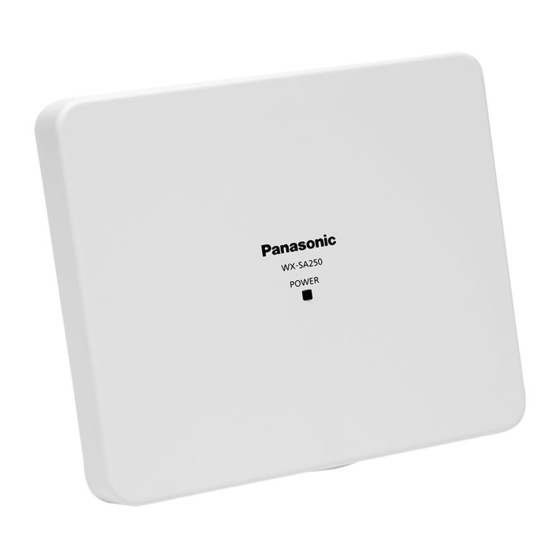
Parts and their names Front Side Rear Side Side (port cover open) - Page 13 A Power indicator [POWER] Shows the operation status of the antenna On (green): Powered Blinking (orange): Pairing Blinking (red): Connection error with the receiver On (red): Communication error with the receiver Off: Not receiving power from either the receiver Important Antenna newly connected after powering ON the receiver Alternately blinking (orange/green): T he support software on the PC connected with the receiver is performing a check When a receiver is in pairing mode, the [POWER] indicator on all the antennas connected to it will blink orange. Refer to the microphone manual and the wireless receiver manual for further details on pairing devices. B Screw cover Used to install the antenna on the ceiling or on a wall. Open this screw cover and tighten the screw inside it to fix the antenna to the fixing bracket. C Hook grooves Used to install the antenna on the ceiling or on a wall. Attach these grooves to the hooks on the fixing bracket. D Cable routing groove Pass the LAN cable (page 16) through this groove to fix it into place.
-
Page 14: Installation
Installation ■ Installation precautions Always ask a retailer to perform these operations. Before installation, set the power switch on the devices you want to connect to OFF. Carefully read the Warning “Precautions” chapter and follow all of its instructions. Also refer to the manual of the devices you are connecting. In order to avoid damages, properly install the antenna to either the ceiling, a wall, or a microphone stand according to the instructions in this manual. When installing the antenna, follow all official ordinances on electrical equipment technical standards. Do not power ON the equipment while installing it. Make sure that all equipment is powered OFF while installing it. Also power OFF all mixers, amplifiers, and other devices connected to the system. Failing to do so will result in a loud noise coming out of the speakers and possibly damaging the system. - Page 15 This system uses the same frequency (1.9 GHz) as other devices which use the DECT standard, such as cordless phones. Using this system on the same floor as a cordless phone or other DECT device may cause interferences and stuttering transmission. Using this system in an environment surrounded by metal (copper, aluminum, iron, etc.) walls, floor, or ceiling may cause the radio waves to be excessively reflected, resulting in a phenomenon known as “multipath fading”. Multipath fading can cause transmission errors Important (such as audio dropouts) even if the signal is strong enough. Make sure that there are no objects such as concrete walls or metal panels (partitions, wall-mounted lockers, doors, etc.) between the antenna and the microphone, as these will obstruct the transmission of radio waves. Placing the antenna at a low place could reduce its range. Do not install the antenna in the following places Places subject to vibration or strong shocks Places exposed to large amounts of humidity and/or dust Places where chemicals are being used, such as pools Places with large amounts of steam or grease, such as kitchens Near speakers, TVs, magnets, and other strong magnetic sources Behind (from the microphone's perspective) blackboards, whiteboards, display, projectors, etc. Near sources of radiation, X-rays, or strong radio waves or magnetism ...
- Page 16 Installation In the following case, contact a retailer beforehand to confirm suitability of the environment for use with the antenna: Using the antenna on a wagon trolley As the antenna uses the same frequency (1.9 GHz) as other DECT devices such as cordless phones, the maximum number of usable microphones may be limited. Power The antenna does not have a power switch. Unplug the LAN cable to turn OFF the antenna. If the cable cannot easily be unplugged because of the way in which the antenna is installed, unplug the power cable of the receiver connected to the antenna. Make sure that all equipment is powered OFF before installing it. Make sure that the equipment is working before installing it. Important Connect the antenna with the receiver and supply power to it. Then confirm that the microphone audio is output from the speaker connected to the receiver. Static electricity Before installing the antenna, discharge yourself by touching a grounded metal object in order to avoid damage caused by static electricity buildup. Tightening screws Tighten screws straight up. After tightening the screws, make visual confirmation that they are straight and well-tightened. Do not use impact screwdrivers or electric screwdrivers, as even the ones with clutches make it difficult to control the torque, and risk damaging the mounting unit. Avoid subjecting the antenna to shocks ...
-
Page 17: Ceiling Installation
■ Ceiling installation Unplug all cables from the antenna and follow these installation procedures. Make an aperture on the ceiling panel Open a circular aperture with diameter of 65 mm Ø65 (2-9/16) (2-9/16 inches) on the ceiling panel. Install the (included) ceiling mounting plate A I nsert the two screws halfway (M4×35 mm, included) in the ceiling mounting plate, so that they protrude from the bracket by 5 mm (3/16 inches) more than the thickness of the ceiling. Holes for the (included) screws on the ceiling mounting plate (two screws) I nsert the screws in the correct mounting unit holes according to the diameter of the aperture in the ceiling. Follow the diagram on the right. For a Ø65 mm For an already (2-9/16 inches) present Ø120 mm aperture (4-3/4 inches) aperture Ceiling mounting plate (included) B P lace the ceiling mounting plate (with two screws inserted halfway into the holes for... - Page 18 Installation Fix the (included) ceiling fixing bracket A S lide the screws of the mounting unit installed in step 2 into the keyhole-shaped holes of the fixing bracket to hold it in place. B F ix the fixing bracket. Pay attention to the direction into which the arrow ( ) is pointing relative to the fixing bracket. The arrow ( ) reflects where the top of the antenna will point. Screw torque: 0.39 N•m to 0.59 N•m {4 kgf•cm to 6 kgf•cm} Mind the direction Fixing bracket (included) Temporary attachment Protuberance Keyhole-shaped holes (two) used for Keyhole-shaped holes (two) used for a Ø65 mm (2-9/16 a Ø120 mm (4-3/4 inches) aperture inches) aperture on on the ceiling the ceiling Important Tighten the screws after sliding them past the protuberances in the Important two keyhole-shaped holes in the fixing bracket to keep the antenna from accidentally falling. Not doing so may cause the antenna to fall.
- Page 19 Use the included cable tie to fix the cable onto the cable tie hook and partially pass it through the routing groove on the rear of the antenna to avoid any excessive pulling force on the cable during installation. Cable tie (included) Cable tie hook Install the antenna A A ttach the antenna to the hooks on the fixing bracket. (Four places) Grooves Hooks Screw cover B O pen the screw cover on the side of the antenna and use the included mounting screw (M3x8 mm) to secure the antenna to the fixing bracket. Screw torque: 0.59 N•m to 0.69 N•m {6 kgf•cm to 7 kgf•cm} C C lose the screw cover. Antenna mounting screw (M3×8 mm) (included) Important Make sure that the mounting screws on the antenna are tightened Important securely to keep the product from falling. Not doing so may cause the antenna to fall. Use a tool such as a torque screwdriver to tighten the screws to the specified torque. Use a magnetic screwdriver. Checking the installation After completing the installation, check that all components are securely fixed.
-
Page 20: Wall Installation (With Fixing Bracket)
Installation ■ Wall installation (with fixing bracket) Unplug all cables from the antenna and follow these installation procedures. When installing the antenna on a wall, place it higher than 1.5 m (59- Important 1/16 inches) from the floor. Placing the antenna at a low place could reduce the range it can cover. In particular, people, metal products, and pieces of furniture placed between the antenna and the microphone may block the radio waves interfering with the transmission, resulting in audio dropouts. Screw the fixing bracket to the wall Fix the fixing bracket to the wall with the four included wood screws (4.1 mm x 25 mm (3/16 inches x 1 inches)). Pay attention to the direction into which the arrow ( ) is pointing relative to the fixing bracket. The arrow ( ) reflects where the top of the antenna will point. Mind the direction Wood screws Fixing bracket (included) (included) The minimum pullout strength required for each wood screw is Important 196 N. Do not install the antenna on gypsum boards, plywood, or walls made of other fragile materials. If you absolutely must do so, make sure that the wall is reinforced enough. - Page 21 Connect the cable to the antenna Connect the LAN cable (page 16) to the antenna. See “Connections” (page 24) for details on connecting the cable. When routing the connection cable to the top of the antenna, first use the included cable tie to fix the cable onto the cable tie hook and partially pass it through the routing groove on the rear as shown in the figure below. Cable tie (included) Cable tie hook When routing the connection cable to the bottom of the antenna, use the included cable tie to fix the cable onto the cable tie hook as shown in the figure below.
- Page 22 Installation Install the antenna A A ttach the antenna to the hooks on the fixing bracket. (Four places) Grooves Hooks B O pen the screw cover on the side of the antenna and use the included mounting screw (M3x8 mm) to secure the antenna to the fixing bracket. Screw Screw torque: 0.59 N•m to 0.69 N•m {6 kgf•cm to Antenna cover 7 kgf•cm} mounting screw (M3×8 mm) C C lose the screw cover. (included) Important Make sure that the mounting screws on the antenna are tightened Important securely to keep the product from falling. Not doing so may cause the antenna to fall. Use a tool such as a torque screwdriver to tighten the screws to the specified torque. Use a magnetic screwdriver. Checking the installation After completing the installation, check that all components are securely fixed.
-
Page 23: Microphone Stand Installation
■ Microphone stand installation When installing the antenna on a microphone stand, place it higher than Important 1 m (39-3/8 inches) from the floor, also make sure that it has an unobstructed line-of-sight to the microphone. Placing the antenna at a low place could reduce the range it can cover. In particular, people, metal products, and pieces of furniture placed between the antenna and the microphone may block the radio waves interfering with the transmission, resulting in audio dropouts. Carefully route the cables so that they do not accidentally trip the microphone stand. Unplug all cables from the antenna and follow these installation procedures. Install the antenna Open the cover on the microphone stand installation hole and insert the microphone stand screw in the hole. Use a microphone stand with an installation screw which is either PF1/2 or W3/8. If the installation screw on the microphone stand is W3/8, use the included conversion screw. Connect the cable to the antenna Connect the LAN cable (page 16) to the antenna. See “Connections” (page 24) for details on connecting the cable. Antenna Mounting screw (PF1/2 or W3/8) LAN cable Microphone stand (locally procured) -
Page 24: Connections
Connections ■ Connecting a receiver After connecting the antenna to a receiver, the antenna is powered, the audio from microphone is transmitted to the receiver, and the audio output is enabled for the amplifiers or speakers which are connected to the receiver. Connect the antenna to the receiver via a LAN cable (page 16) Antenna (side) Wireless receiver connector (inside the connector cover) LAN cable To AC120 V Wireless antenna 60 Hz connectors 1 to 8 electric outlet Receiver ... -
Page 25: Dimensions
Dimensions Unit: mm (inch) 185 (7-5/16) (1-1/4) -
Page 26: Troubleshooting
Troubleshooting Please check the common problems listed in this table before seeking professional help. If none of the tips provided here help, if you are dealing with a problem not listed here, or if you are otherwise uncertain, contact your retailer for more information. Reference Phenomenon Cause/measure page Is the antenna being powered? The [POWER] indicator stays off ¨ Make sure that the antenna is connected to ¨ the receiver. Has the antenna been newly connected after powering ON the receiver? ¨ Power OFF the receiver before adding new ¨ antennas. A communication error with the receiver has The [POWER] ― indicator lights red occurred. -
Page 27: Specifications
Specifications Wireless Used frequencies 1921.536 MHz to 1928.448 MHz Antenna Internal antenna Reception Diversity reception Power Connector RJ-45 Compatible cables Cat5, Cat5e, or Cat6 straight (non-crossover) LAN cable Power source Wireless receiver (WX-SR202P) Antenna field selection Three-step selection (selection performed through the support software on a PC connected to the WX-SR202P wireless receiver) Display (indicators) Power Operating temperature range -10 °C to +50 °C (14 °F to 122 °F) Operating humidity range 10 % to 90 % (no condensation) Dimensions Approx. 185 mm (W) x 160 mm (H) x 32 mm (D) (7-5/16 inches x 6-5/16 inches x 1-1/4inches) Mass Approx. 400 g (0.88 lb) Finish White finish Installation Ceiling, wall, microphone stand Water resistance IPx4, splash resistance... -
Page 28: Standard Accessories
Specifications Standard accessories Operating Instructions (this booklet) ..................1 Warranty Card ........................1 Ceiling mounting plate ......................1 Fixing bracket ........................1 Ceiling mounting screws (M4×35 mm) ..................2 Antenna mounting screw (M3×8 mm) ...................1 Wood screws (4.1 mm x 25 mm) ...................4 Cable tie ..........................1 Conversion screw (from PF1/2 to W3/8)* ................1 * Shipped with attached to the product... -
Page 29: Précautions De Sécurité
Précautions de sécurité Avertissement d’exposition RF de la FCC : Pour respecter les exigences de la FCC en matière d’exposition aux radiofréquences dans un environnement non contrôlé : − C et équipement doit être installé et utilisé conformément aux instructions fournies et un espacement minimal de 20 cm (8 pouces) doit être prévu entre l’antenne et le corps de toute personne (excluant les extrémités des mains, des poignets, des pieds et des chevilles) dans les modes de fonctionnement sans fil. - Page 30 ATTENTION : Déclaration de conformité UN DISPOSITIF DE DÉCONNEXION du fournisseur FACILEMENT ACCESSIBLE DOIT Nom commercial : ÊTRE INCORPORÉ À L’ÉQUIPEMENT Panasonic ALIMENTÉ PAR UNE SOURCE N° de modèle : WX-SA250P D’ALIMENTATION DE 24 V CC. Partie responsable : Ces instructions d’entretien sont Panasonic Corporation of North America réservées au personnel d’entretien Two Riverfront Plaza, Newark, NJ qualifié. Pour réduire le risque de choc 07102-5490 électrique, n’effectuez aucun autre Contact de support technique : entretien que celui indiqué...
- Page 31 Pour le Canada. RSS-Gen En vertu de la réglementation d’Industrie Canada, cet émetteur radio ne peut fonctionner qu’avec une antenne dont le type et le gain maximal (ou inférieur) sont approuvés pour l’émetteur par Industrie Canada. Pour réduire les interférences radio potentielles avec les autres utilisateurs, le type d’antenne et son gain doivent être sélectionnés de manière à...
-
Page 32: Aperçu Du Produit
Aperçu du produit Ce produit est une antenne sans fil qui s’utilise avec un microphone sans fil (WX-ST200P ou WX-ST400P, tous deux vendus séparément). Il doit être connecté à un récepteur sans fil (WX-SR202P : vendu séparément) pour fonctionner. Il utilise un système basé sur la norme DECT 1,9 GHz* pour obtenir une connexion stable sur une large zone, ce qui permet d’obtenir un son clair avec peu d’interférences. * D ECT (Digital Enhanced Cordless Telecommunications) est une norme de communication numérique sans fil. L’installation est facile et peut être effectuée au plafond, au mur ou sur un pied de microphone. Ce produit peut également être installé à l’extérieur (IPx4, résistance aux éclaboussures). Il peut être placé dans n’importe quel endroit où il ne sera pas directement soumis à la pluie (ex : sous un avant-toit). Limitation de responsabilité CETTE PUBLICATION EST FOURNIE « EN L’ÉTAT » SANS GARANTIE D’AUCUNE SORTE, EXPRESSE OU IMPLICITE, Y COMPRIS, MAIS SANS S’Y LIMITER, LES GARANTIES IMPLICITES DE QUALITÉ MARCHANDE, D’ADAPTATION À UN USAGE PARTICULIER OU DE NON-VIOLATION DES DROITS DU TIERS. CETTE PUBLICATION PEUT CONTENIR DES INEXACTITUDES TECHNIQUES OU DES ERREURS TYPOGRAPHIQUES. DES MODIFICATIONS SONT AJOUTÉES AUX INFORMATIONS CONTENUES DANS LE PRÉSENT DOCUMENT, À TOUT MOMENT, EN VUE D’AMÉLIORER LA PRÉSENTE PUBLICATION ET/OU LE(S) PRODUIT(S) CORRESPONDANT(S). -
Page 33: Déni De La Garantie
Déni de la garantie EN AUCUN CAS Panasonic Corporation NE SERA TENU POUR RESPONSABLE POUR TOUTE PARTIE OU TOUTE PERSONNE, À L’EXCEPTION DU REMPLACEMENT OU D’UNE MAINTENANCE RAISONNABLE DE CE PRODUIT POUR LES CAS CITÉS, INCLUS MAIS NON LIMITÉS À CE QUI SUIT : A T OUT DOMMAGE OU PERTE, Y COMPRIS SANS LIMITATION, DIRECT OU INDIRECT, SPÉCIAL, IMPORTANT OU EXEMPLAIRE, SURVENANT OU CONCERNANT LE PRODUIT ; B B LESSURE PERSONNELLE OU TOUT DOMMAGE CAUSÉ PAR UN USAGE NON APPROPRIÉ OU UNE UTILISATION NÉGLIGENTE DE L’UTILISATEUR ; C T OUT DYSFONCTIONNEMENT OU PROBLÈME RÉSULTANT D’UN DÉMONTAGE, D’UNE RÉPARATION OU D’UNE MODIFICATION NON AUTORISÉS DU PRODUIT EFFECTUÉS PAR L’UTILISATEUR, QUELLE QUE SOIT LA CAUSE DUDIT DYSFONCTIONNEMENT OU PROBLÈME ; D T OUT PROBLÈME CAUSANT UNE DÉFAILLANCE DE LA TRANSMISSION DU SIGNAL ENTRAÎNANT DES INCONVÉNIENTS, DES PERTES OU DES DOMMAGES CONSÉCUTIFS, SURVENANT DE CAUSES TELLES QU’UN DYSFONCTIONNEMENT DU SYSTÈME, UN DÉFAUT, UNE CONFIGURATION OU UNE INSTALLATION. E T OUT PROBLÈME, DÉSAGRÉMENT CONSÉCUTIF OU PERTE OU DOMMAGE, SURVENANT DU SYSTÈME COMBINÉ AVEC DES DISPOSITIFS DE TIERS. F L ’IMPOSSIBILITÉ D’UTILISER LE PRODUIT OU TOUT INCONVÉNIENT, PERTE OU DOMMAGE RÉSULTANT DE L’IMPOSSIBILITÉ D’UTILISER LE PRODUIT EN RAISON... -
Page 34: Abréviations
Précautions de sécurité Abréviations Ce manuel utilise les abréviations suivantes. “Ce produit”, ou l’“antenne” désigne l’“antenne sans fil (WX-SA250P : vendue séparément)”. Le “microphone” désigne le “microphone sans fil (WX-ST200P ou WX-ST400P, tous deux vendus séparément)”. Le “récepteur sans fil” ou le “récepteur” désigne le “récepteur sans fil (WX-SR202P : vendu séparément)”. Le “PC” désigne l’“ordinateur personnel”. Toutes les informations sur les produits vendus séparément contenues dans ce manuel sont des mises à jour de juin 2019. Consultez un détaillant pour obtenir les renseignements les plus récents. - Page 35 Table des matières Précautions de sécurité ……………… 29 Aperçu du produit ………………………… 32 Limitation de responsabilité …………… 32 Déni de la garantie ……………………… 33 Droits d'auteur …………………………… 33 Abréviations ……………………………… 34 Précautions ……………………………… 36 Précautions d’utilisation ……………… 38 Nomenclature des pièces …………… 39 Installation ……………………………… 41 Précautions d’installation ………………...
-
Page 36: Précautions
Précautions Serrer les vis et les boulons avec les outils spécifiés Le non-respect de cette consigne pourrait entraîner la chute de pièces provoquant des accidents et des blessures. Installer le produit de façon à ce que son poids soit correctement supporté Le non-respect de cette consigne pourrait entraîner la chute de l’antenne provoquant des accidents et des blessures. Assurez-vous que la méthode d’installation que vous avez choisie offre un support suffisant avant d’installer l’antenne. Installer correctement l’antenne au plafond, au mur ou sur un pied de microphone en suivant les instructions d’installation. - Page 37 Ne pas utiliser à proximité de gaz inflammables Cela pourrait entraîner des explosions et des blessures. Ne pas utiliser pas le produit s’il y a un risque de dommage par de l’eau de mer ou des gaz corrosifs L’unité de montage risque de se détériorer et d’entraîner des accidents et des blessures. Ne pas laisser entrer de substances étrangères dans le produit L’eau ou les métaux pénétrant dans l’antenne pourraient provoquer des incendies ou des chocs électriques.
-
Page 38: Précautions D'utilisation
Précautions d’utilisation En dehors de ce qui précède “Précautions”, assurez-vous de suivre les points ci-dessous. Utiliser ce produit avec précaution Ce produit contient des composants délicats qui peuvent être endommagés par une utilisation ou un stockage inappropriés. Réparez ou remplacez tout composant endommagé. Plage de température de fonctionnement Entre -10 °C (50 °F) et +50 °C (122 °F). L’utilisation du produit en dehors de cette plage pourrait entraîner un dysfonctionnement ou l’endommager. Alimentation électrique L’antenne n’a pas d’interrupteur d’alimentation. Débranchez le câble LAN (page 43) pour éteindre l’antenne. Si le câble ne peut pas être facilement débranché en raison de la façon dont l’antenne est installée et si l’antenne est connectée à... -
Page 39: Nomenclature Des Pièces
Nomenclature des pièces Avant Côté Arrière Côté Côté (cache-port ouvert) - Page 40 Précautions d’utilisation A Voyant d’alimentation [POWER] Montre l’état de fonctionnement de l’antenne Allumé (vert) : Sous tension Clignotant (orange) : Appairage Clignotant (rouge) : Erreur de connexion avec le récepteur Allumé (rouge) : Erreur de communication avec le récepteur Éteint : Aucune tension provenant des récepteurs A ntenne nouvellement connectée après la mise sous tension du Important récepteur Clignotant alternativement (orange/vert) : Le logiciel de soutien sur le PC connecté au récepteur effectue un contrôle ...
-
Page 41: Installation
Installation ■ Précautions d’installation Demandez toujours à un détaillant d’effectuer ces opérations. A vant l’installation, réglez l’interrupteur d’alimentation sur les dispositifs que vous souhaitez connecter sur Avertissement OFF. Lisez attentivement le chapitre “Précautions” et suivez toutes les instructions. Reportez-vous également au manuel des dispositifs que vous connectez. Afin d’éviter tout dommage, installez correctement l’antenne au plafond, sur un mur ou sur un pied de microphone en suivant les instructions de ce manuel. - Page 42 Installation Ce système utilise la même fréquence (1,9 GHz) que les autres dispositifs qui utilisent la norme DECT, comme les téléphones sans fil. L’utilisation de ce système au même étage qu’un téléphone sans fil ou un autre dispositif DECT peut provoquer des interférences et des bégaiements de transmission. L’utilisation de ce système dans un environnement entouré de murs, d’un plancher ou d’un plafond en métal (cuivre, aluminium, fer, etc.) peut provoquer une réflexion excessive des ondes radio, entraînant un phénomène appelé “évanouissement par trajets multiples”.
- Page 43 Dans le cas suivant, contactez au préalable un détaillant pour vérifier si l’environnement est adapté à l’utilisation de l’antenne : Utilisation de l’antenne sur un chariot Comme l’antenne utilise la même fréquence (1,9 GHz) que les autres dispositifs DECT tels que les téléphones sans fil, le nombre maximum de microphones utilisables pourrait être limité. Alimentation électrique L’antenne n’a pas d’interrupteur d’alimentation. Débranchez le câble LAN pour éteindre l’antenne. Si le câble ne peut pas être facilement débranché en raison de la façon dont l’antenne est installée, débranchez le câble d’alimentation du récepteur connecté à l’antenne. Assurez-vous que tout l’équipement est hors tension avant l’installation. Assurez-vous que l’équipement fonctionne avant de l’installer. Important Connectez l’antenne au récepteur et fournissez-lui l’alimentation électrique. Confirmez ensuite que l’audio du microphone est émis par le haut-parleur connecté au récepteur. Électricité...
-
Page 44: Installation Au Plafond
Installation ■ Installation au plafond Débranchez tous les câbles de l’antenne et suivez ces procédures d’installation. Faire une ouverture sur le panneau de plafond Ouvrez une ouverture circulaire d’un diamètre de Ø65 (2-9/16) 65 mm (2-9/16 po) sur le panneau de plafond. Installer la plaque de montage au plafond (fournie) A Insérez les deux vis à mi-chemin (M4×35 mm, fournies) dans la plaque de montage au plafond, de sorte qu’elles dépassent de l’étrier de 5 mm (3/16 po) de plus que l’épaisseur du plafond. Trous pour les vis (fournies) sur la plaque de montage au plafond (deux vis) Insérez les vis dans les trous de l’unité... - Page 45 Fixer l’étrier de fixation au plafond (fourni) A Faites glisser les vis de l’unité de montage installée à l’étape 2 dans les trous en forme de serrure de l’étrier de fixation pour le maintenir en place. B Fixez l’étrier de fixation. Faites attention à la direction indiquée par la flèche ( ) par rapport à...
- Page 46 Installation Utilisez le serre-câble fourni pour fixer le câble sur le crochet de serre-câble et faites-le passer partiellement par la rainure d’acheminement à l’arrière de l’antenne afin d’éviter toute force de traction excessive sur le câble pendant l’installation. Serre-câble (fourni) Crochet de serre-câble Installer l’antenne A F ixez l’antenne aux crochets sur l’étrier de fixation. (Quatre emplacements) Rainures Crochets Cache de vis B O uvrez le cache de vis sur le côté de l’antenne et utilisez la vis de montage fournie (M3x8 mm) pour sécuriser l’antenne sur l’étrier de fixation. Couple de serrage des vis : 0,59 N•m à 0,69 N•m {6 kgf•cm à 7 kgf•cm} C Fermez le cache de vis.
-
Page 47: Installation Au Mur (Avec L'étrier De Fixation)
■ Installation au mur (avec l’étrier de fixation) Débranchez tous les câbles de l’antenne et suivez ces procédures d’installation. Quand vous installez l’antenne sur un mur, placez-la à plus de 1,5 m Important (59-1/16 po) du sol. Placer l’antenne à un endroit bas pourrait réduire la portée qu’elle peut atteindre. En particulier, les personnes, les produits métalliques et les meubles placés entre l’antenne et le microphone pourraient bloquer les ondes radio interférant avec la transmission, ce qui peut entraîner des pertes audio. Visser l’étrier de fixation au mur Fixez l’étrier de fixation au mur avec les quatre vis à bois fournies (4,1 mm x 25 mm (3/16 po x 1 po)). Faites attention à la direction indiquée par la flèche ( ) par rapport à l’étrier de fixation. - Page 48 Installation Connecter le câble à l’antenne Connectez le câble LAN (page 43) à l’antenne. Voir “Connexions” (page 51) pour plus de détails sur la connexion du câble. Quand vous acheminez le câble de connexion vers le haut de l’antenne, utilisez d’abord le serre-câble fourni pour fixer le câble sur le crochet de serre-câble et faites-le passer partiellement par la rainure d’acheminement à l’arrière comme indiqué sur la figure ci-dessous. Serre-câble (fourni) Crochet de serre-câble Quand vous acheminez le câble de connexion vers le bas de l’antenne, utilisez d’abord le serre-câble fourni pour fixer le câble sur le crochet de serre-câble comme indiqué sur la figure ci-dessous.
- Page 49 Installer l’antenne A F ixez l’antenne aux crochets sur l’étrier de fixation. (Quatre emplacements) Rainures Crochets B O uvrez le cache de vis sur le côté de l’antenne et utilisez la vis de montage fournie (M3x8 mm) pour sécuriser l’antenne sur l’étrier de fixation. Cache Couple de serrage des vis : 0,59 N•m à 0,69 N•m Vis de de vis {6 kgf•cm à 7 kgf•cm} montage d’antenne C Fermez le cache de vis. (M3×8 mm) (fournie) ...
-
Page 50: Installation Du Pied De Microphone
Installation ■ Installation du pied de microphone Lors de l’installation de l’antenne sur un pied de microphone, placez-la à Important plus de 1 m (39-3/8 po) du sol et assurez-vous qu’elle ne gêne pas la ligne de visée du microphone. Placer l’antenne à un endroit bas pourrait réduire la portée qu’elle peut atteindre. En particulier, les personnes, les produits métalliques et les meubles placés entre l’antenne et le microphone pourraient bloquer les ondes radio interférant avec la transmission, ce qui peut entraîner des pertes audio. Acheminez avec précaution les câbles de manière à ce qu’ils ne fassent pas trébucher accidentellement le pied de microphone. Débranchez tous les câbles de l’antenne et suivez ces procédures d’installation. Installer l’antenne Ouvrez le cache de l’orifice d’installation du pied de microphone et insérez la vis du pied de microphone dans l’orifice. Utilisez un pied de microphone avec une vis d’installation PF1/2 ou W3/8. Si la vis d’installation sur le pied de microphone est une W3/8, utilisez la vis de conversion fournie. Connecter le câble à l’antenne Connectez le câble LAN (page 43) à l’antenne. Voir “Connexions” (page 51) pour plus de détails sur la connexion du câble. -
Page 51: Connexions
Connexions ■ Connexion d’un récepteur Après avoir connecté l’antenne à un récepteur, l’antenne est sous tension, l’audio du microphone est transmis au récepteur et la sortie audio est activée pour les amplificateurs ou haut-parleurs qui sont connectés au récepteur. Connecter l’antenne au récepteur via un câble LAN (page 43) Antenne (côté) Connecteur de récepteur sans fil (à l’intérieur du cache de connecteur) Câble LAN Vers la prise de Connecteurs de... -
Page 52: Dimensions
Dimensions Unité : mm (pouce) 185 (7-5/16) (1-1/4) -
Page 53: Diagnostic Des Pannes
Diagnostic des pannes Vérifiez les problèmes courants énumérés dans ce tableau avant de demander l’aide d’un professionnel. Si aucun des conseils fournis ici ne sont utiles, si vous rencontrez un problème non répertorié ici, ou en cas de doutes, contactez le détaillant pour plus d’informations. Page de Phénomène Cause/mesure référence L’antenne est-elle sous tension? Le voyant [POWER] reste éteint ¨... -
Page 54: Spécifications
Spécifications Sans fil Fréquences utilisées 1921.536 MHz à 1928.448 MHz Antenne Antenne interne Réception Réception en diversité Alimentation Connecteur RJ-45 électrique Câbles compatibles Câble LAN droit (non croisé) Cat5, Cat5e ou Cat6 Source d’alimentation Récepteur sans fil (WX-SR202P) Sélection du champ d’antenne Sélection en trois étapes (sélection effectuée par le logiciel de soutien sur un PC connecté au récepteur sans fil WX-SR202P) Affichage (voyants) Alimentation électrique... -
Page 55: Accessoires Standard
Accessoires standard Instructions d’utilisation (ce livret)..................1 Carte de garantie ........................1 Plaque de montage au plafond....................1 Étrier de fixation........................1 Vis de montage au plafond (M4×35 mm) ................2 Vis de montage de l’antenne (M3×8 mm) ................1 Vis à bois (4,1 mm x 25 mm) ....................4 Serre-câble ..........................1 Vis de conversion (de PF1/2 à W3/8)* ..................1 * Livré attaché au produit... - Page 56 Panasonic will not take responsibility for any accident or damage caused by using the product with methods or parts other than those specified in this manual. Damages hence suffered by the product will not be covered by the warranty. Panasonic Corporation of North America Two Riverfront Plaza, Newark, NJ 07102-5490 http://business.panasonic.com/...