
Related Manuals for NEC AB-050-FX3-U


Summary of Contents for NEC AB-050-FX3-U
- Page 1 User’s Manual AB-050-FX3-U V850ES/Fx3 Starter Board Hardware Document No. EASE-UM-0019-2.1 Date Published February 2007 © NEC Electronics 2007...
- Page 2 NEC Electronics products listed in this document or any other liability arising from the use of such NEC Electronics products. No license, express, implied or otherwise, is granted under any patents, copyrights or other intellectual property rights of NEC Electronics or others.
-
Page 3: Table Of Contents
NEC Electronics (Europe) GmbH Table of Contents Introduction ................................6 Board description..............................7 Overview ................................7 2.1.1 Electrical Area ............................7 2.1.2 Functional Area ............................8 2.1.3 Connecting both areas ..........................8 Reset................................9 NWire connection ............................9 PG-FP4 connection ............................9 RS-232 / LIN ..............................10 CAN ................................13 Mounting the FK3 device on the board .......................14 Connecting the Power Supply ..........................15... - Page 4 NEC Electronics (Europe) GmbH List of Figures Figure 1 AB-050-FX3-U with FK3 Device........................6 Figure 2-1 Board overview ............................7 Figure 2-2 Pin Patch Area ............................8 Figure 3-1 FK3 device mounting (1)........................14 Figure 3-2 FK3 device mounting (2)........................14 Figure 5-1 UART / LIN DSUB connectors ......................16 Figure 5-2 CAN DSUB connector...........................17...
- Page 5 NEC Electronics (Europe) GmbH List of Tables Table 2-1 Overview of functional signals ........................8 Table 2-2 CN48 – Nwire............................9 Table 2-3 FP4 (CSI) Jumpers ..........................9 Table 2-4 FP4 (UART) Jumpers..........................10 Table 2-5 UARTDn signal jumpers ........................10 Table 2-6 RS-232 signal jumpers..........................11 Table 2-7 LIN bus signal jumpers..........................12...
-
Page 6: Introduction
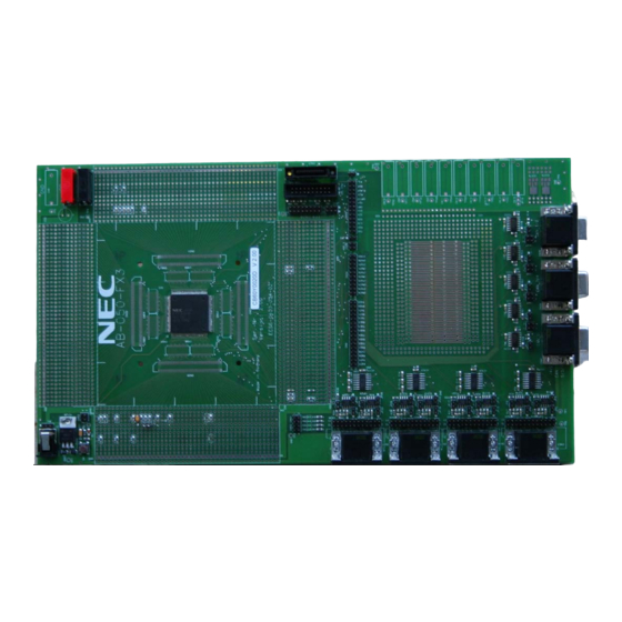
NEC Electronics (Europe) GmbH Introduction The AB-050-FX3-U is designed as a simple and easy to use Starter Board to support users with the first steps when starting with the Fx3-Series family. The Starter Board is prepared to hold a V850ES/FK3 device (uPD70F3385). As the largest device of the Fx3- Series the FK3 offers the complete range of all Fx3 peripherals. -
Page 7: Board Description
NEC Electronics (Europe) GmbH Board description 2.1 Overview JP22 CN23 Pin Patch Area JP15 CN28 JP11 JP26 CN47 CN49 CN31 JP27 CN46 CN53 CN54 JP28 CN45 JP29 CN44 CN55 CN56 CN29 CN52 CN36 CN35 CN34 CN33 CN22 CN21 CN20 CN19... -
Page 8: Functional Area
NEC Electronics (Europe) GmbH SMD2 SMD1 Device signal Figure 2-2 Pin Patch Area A component assembled to the SMD1 field will therefore be connected between the device pin and VSS. A component assembled to the SMD2 field will be connected between the device pin and VCC. -
Page 9: Reset
Open CN52 3-4 to disconnect the onboard Reset circuitry from the device. 2.3 NWire connection The NWire debug cable from a NEC Debug Tool (e.g. MiniCube) can be connected to CN2. Additionally a KEL connector (CN23) is available to connect third party NWire Debug Tools. -
Page 10: Rs-232 / Lin
NEC Electronics (Europe) GmbH To program the device via the UART interface the following jumpers must be closed: Connector Pin number JP15 1 – 2 JP11 1 – 2 1 – 2 CN48 3 – 4 Table 2-4 FP4 (UART) Jumpers For Flash programming using the PG-FP4 device power can either be supplied by the PG-FP4 or by the AB-050- FX3. -
Page 11: Table 2-6 Rs-232 Signal Jumpers
NEC Electronics (Europe) GmbH To connect the RS-232 / LIN bus driver signals to the RS-232 / LIN bus connecters close the following jumpers: Signal Connector Pin # TXD0 1 – 2 UARTD0 CN19 RXD0 3 – 4 5 – 6 TXD1 1 –... -
Page 12: Table 2-7 Lin Bus Signal Jumpers
NEC Electronics (Europe) GmbH To connect the LIN bus driver signals to the related RS-232/LIN bus connector close the following jumpers: Signal Connector Pin # 7 – 8 LIN0 CN19 9 – 10 11 – 12 7 – 8 LIN1 9 –... -
Page 13: Can
NEC Electronics (Europe) GmbH The RxD pin of the LIN driver (pin #1) is an open drain output. The necessary pull-up resistor in order to interface to the Fx3 device is not assembled on the board. To enable operation of the RxD signal either connect an appropriate pull up resister to the related RxD input pin of the LIN channel, or enable the internal Pull-Up resistors available in the Fx3 devices for each LIN input pin. -
Page 14: Mounting The Fk3 Device On The Board
To mount a FK3 device on the AB-050-FX3-U place the package in the top right corner of the SMD area. As the FK3 with 176 pins is placed on an SMD area with 180 pins 4 pads will not be used. Due to the alignment of the device in the top right corner two pads in the lowest line and two pads in the left most line remain empty. -
Page 15: Connecting The Power Supply
NEC Electronics (Europe) GmbH Connecting the Power Supply Power can be supplied to the board either a) by directly supplying the device operating voltage, or b) via the onboard 7805 type voltage regulator. Direct voltage supply: A direct supply of the device operating voltage can either be implied by using CN7 to connect VCC (typical +5V for Fx3 devices) and CN8 to connect VSS (0V), or by using CN1. -
Page 16: Uart / Lin Can Dsub Connectors
To physically connect the Starter Board to other UART / LIN / CAN devices DSUB type connectors are available.. 5.1 UART / LIN connectors To interface the AB-050-FX3-U board to external to UART / LIN devices a 9 pin male D-SUB connector is supplied for each of the eight available UART / LIN interfaces. -
Page 17: Can Connectors
NEC Electronics (Europe) GmbH 5.2 CAN connectors To interface the AB-050-FX3-U board to external CAN devices a 9 pin female D-SUB connector is supplied for each of the five available CAN interfaces. The pin functions of the CAN DSUB connectors can be seen in Table 5-2. -
Page 18: Mounting Other Fx3 Devices On The Board
6.1.1 Mounting a FE3 device To mount a FE3 device on the AB-050-FX3-U place the package in the lower left corner of the SMD area but do not use the two pins most in the corner. Place pin 1 of the device on pin 2 of the SMD area. -
Page 19: Mounting A Ff3 Device
6.1.2 Mounting a FF3 device To mount a FF3 device on the AB-050-FX3-U place the package in the lower left corner of the SMD area but do not use the two pins most in the corner. Place pin 1 of the device on pin 2 of the SMD area. -
Page 20: Mounting A Fj3 Device
NEC Electronics (Europe) GmbH 6.1.4 Mounting a FJ3 device To mount a FJ3 device on the AB-050-FX3-U place the package in the lower left corner of the SMD area. Place pin 1 of the device on pin 1 of the SMD area. -
Page 21: Pin Connection
NEC Electronics (Europe) GmbH 6.2 Pin connection 6.2.1 Power supply pins Connect the devices power supply pins to the related power lines using the available SMD pads in the Pin Patch Areas. Refer to the Fx3 User’s Manual and Table 6-1 for the location of the VDD and VSS pins on the different devices. -
Page 22: Regc Pin
NEC Electronics (Europe) GmbH To connect the devices VDD pins to the VDD lane of the board place a 0 Ohm resistor on the SMD2 pad and place a 100 nF buffering capacitor on the SMD1 pad. Fx3 pinning Signal... -
Page 23: X1, X2 Pins
NEC Electronics (Europe) GmbH 6.2.3 X1, X2 pins An external oscillator can be connected to the X1 and X2 pins of the device. Connect the oscillator between the X1 and X2 pins and place a small capacitor on the SMD1 areas of those pins. -
Page 24: Xt1, Flmd0
NEC Electronics (Europe) GmbH 6.2.4 XT1, FLMD0 A pull-down resistor should be connected to input pins XT1 and FLMD0. Device signal Figure 6-8 Pins with Pull-Down Refer to the Fx3 User’s Manual and Table 6-5 for the location of the XT1 and FLMD0 pins on the different devices. -
Page 25: Functional Pin Connection
NEC Electronics (Europe) GmbH 6.3 Functional pin connection As the routing of the functional signals (Reset, UARTDn, CANn, NWIRE and FP4) between the device SMD pad area and the Jumpers connecting the Electrical Area and Functional Area is based on the FK3 device, the routing of those signals for other Fx3 devices must be place manually. -
Page 26: Testpoints
NEC Electronics (Europe) GmbH The different jumper groups are highlighted in different colours according to their related functionality: Jumper colour Related functionality NWire Debug interface and Flash Yellow programming interface Green CAN interface signals Blue RS-232 interface signals LIN bus interface signals... -
Page 27: Nwire Signals
NEC Electronics (Europe) GmbH 6.3.4 NWIRE signals To connect the NWIRE signals place wires according to the table below: Fx3 pin number CN48 Signal pin number DRSTZ RESET FLMD0 Table 6-8 NWire interface signals 6.3.5 Flash Programming interface To connect the Flash Programming signals place wires according to the table below:... -
Page 28: Can Interface
NEC Electronics (Europe) GmbH 6.3.6 CAN interface To connect the CAN interface signals place wires according to the table below: Fx3 pin number CN24 Pin Signal number 25 (*) 25 (*) 28 (*) 28 (*) 49 (*) CTXD0 26 (*) -
Page 29: Uartd Interface
NEC Electronics (Europe) GmbH 6.3.7 UARTD interface To connect the UARTD interface signal place wires according to the table below: Fx3 pin number Signal TxD0 RxD0 TxD1 RxD1 TxD2 RxD2 60 (*) 81 (*) TxD3 59 (*) 80 (*) RxD3... -
Page 30: Revision History
Error! Reference Added chapter for cable description source not found. Added information on LIN operation Update for V2.0 revision of the AB-050-FX3 board. Updated naming of board to AB-050-FX3-U Added Caution on UART / LIN driver usage - 30 -... -
Page 31: Appendix A - Pin Number Templates
NEC Electronics (Europe) GmbH Appendix A – Pin Number templates If wanted the tables below can be printed and the pin numbers for the device placed on the AB-050-FX3-U glued to board. This allows for an easer handling of the devices pins. -
Page 32: Appendix B - Schematic
NEC Electronics (Europe) GmbH Appendix B - Schematic - 32 -... - Page 33 LVDD connector LVDD PIN20 PIN40 PIN60 PIN80 PIN100 notass notass notass notass notass AB-050-FK3 4pins 4pins 4pins 4pins 4pins connector connector connector connector connector notass notass notass notass notass Page Sheet1 EESS-0400-034-02 NEC EE ETC DT NEC Corporation Distribution:...
- Page 34 LVDD LVDD LVDD LVDD PIN144 PIN140 PIN120 PIN161 notass notass notass notass AB-050-FK3 4pins 4pins 4pins 4pins connector connector notass notass connector connector connector connector Sheet2 Page notass notass notass notass EESS-0400-034-02 NEC EE ETC DT Distribution: NEC Corporation...
- Page 35 PIN35 PIN98 Scale PIN36 PIN97 Designed Checked Approved PIN37 PIN96 PIN38 PIN95 PIN39 PIN94 PIN40 PIN93 PIN41 PIN92 Spec. PIN42 PIN91 Assembly drawing PIN43 PIN90 PIN44 PIN89 AB-050-FK3 Multi QFP176 Footprint Page EESS-0400-034-02 NEC EE ETC DT Distribution: NEC Corporation...
- Page 36 PIN97 Scale PIN37 PIN96 Designed Checked Approved PIN38 PIN95 PIN39 PIN94 PIN40 PIN93 PIN41 PIN92 Spec. PIN42 PIN91 Assembly PIN43 PIN90 drawing PIN44 PIN89 AB-050-FK3 Board VER. 1.00 QFP180 Footprint Page EESS-0400-034-02 NEC EE ETC DT Distribution: NEC Electron Devices...
- Page 37 PIN43 PIN43 PIN43 PIN43 PIN89 PIN89 PIN44 PIN44 PIN44 PIN44 Scale CN31 50pins/54722/Socket Designed Checked Approved 50pins/54722/Socket CN54 100pins/AXN/Socket CN56 NAIS/AXN300130S Spec. Assembly drawing AB-050-FK3 Board VER. 1.00 PiggyPack Connectors Page EESS-0400-034-02 NEC EE ETC DT Distribution: NEC Electronics Corporation...
- Page 38 2pins TTL_R2_3_OUT NWAKE TR2_3_GND AB-050-FK3 LIN_2_1_12V LIN_2_2_12V LIN_2_3_12V TTL_T2_3_IN LIN_2_3_12V LIN_2_3_LIN JP25 IC223 TJA1020 gnd1 gnd1 gnd1 UART/LIN Page R2_3_IN_CN_LINGND gnd2 gnd2 gnd2 12.0 2pins 12pins gnd3 gnd3 gnd3 EESS-0400-034-02 gnd4 gnd4 gnd4 NEC EE ETC DT Distribution: NEC Corporation...
- Page 39 Spec. CANH CANH_4 Driver Assembly CANL CANL_4 drawing 5V_2 5V_2 SPLIT GND_4 AB-050-FK3 VBAT Board VER. 1.00 WAKE 2pins CAN/POWER/RESET Page IC230 TJA1041 NOT ass EESS-0400-034-02 NEC EE ETC DT Distribution: NEC Electronics Corporation...
- Page 40 10pf/63V/eia0805 100nf/63V/eia0805 GND8 GND9 10pf/63V/eia0805 100nf/63V/eia0805 TVDO GND10 TVDD 100nf/63V/eia0805 20pins/straight/male/housing/NWIRE Debug 100nf/63V/eia0805 100nf/63V/eia0805 CN23 Scale Designed Checked Approved Spec. Assembly JP22 drawing AB-050-FK3 Board VER. 1.00 2pins 26pins Nwire/FP4 Page EESS-0400-034-02 NEC EE ETC DT Distribution: NEC Electronics Corporation...