Table of Contents
Quick Links
FAILURE TO READ AND FOLLOW ALL INSTRUCTIONS CAREFULLY BEFORE
INSTALLING OR OPERATING THIS CONTROL COULD CAUSE PERSONAL
INJURY AND/OR PROPERTY DAMAGE.
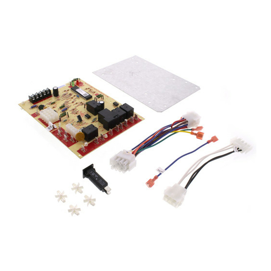
Kit includes:
1 – 50A66-843 ignition control board
1 – Wiring harness (9-pin to 12-pin)
1 – Wiring harness (4-pin to 6-pin)
1 – Mounting panel
4 – Stand-off fasteners
1 – Circuit breaker
1 – 4" blue wire
2 – Wiring diagrams
The kit includes the 50A66-843 which is an automatic gas
interrupted ignition control that employs a microprocessor
to continually monitor, analyze, and control the proper
operation of the gas burner, inducer, and fan.
These controls incorporate system fault analysis for quick
gas flow shut-off, coupled with automatic ignition retry
upon sensing a fault correction.
Installation should be done by a qualified heating and air
conditioning contractor or licensed electrician.
If in doubt about whether your wiring is millivolt, line, or
low voltage, have it inspected by a qualified heating and
air conditioning contractor or licensed electrician.
Do not exceed the specification ratings.
All wiring must conform to local and national electrical
codes and ordinances.
This control is a precision instrument, and should be
handled carefully. Rough handling or distorting compo-
nents could cause the control to malfunction.
Following installation or replacement, follow manufacturer's
recommended installation/service instructions to ensure
proper operation.
CAUTION
!
Do not short out terminals on gas valve or primary
control. Short or incorrect wiring may damage
the thermostat.
Integrated Single Stage
Furnace Control Replacement Kit
INSTALLATION INSTRUCTIONS
The 21D83M-843 kit will replace the following Controls:
Lennox
10M9301
32M8801
12L6901
56L8401
24L8501
63K8901
97L4801
100925-01
30W2501
100925-03
69M0801
17W9201
69M1501
23W5101
83M00
Follow instructions for replacement of your model num-
ber under the heading INSTALLATION.
Failure to comply with the following warnings
could result in personal injury or property damage.
FIRE HAZARD
• Do not exceed the specified voltage.
• Replace existing control with exact model
and dash number.
• Protect the control from direct contact with
water (dripping, spraying, rain, etc.).
• If the control has been in direct contact with
water, replace the control.
• Label all wires before disconnection when
servicing controls. Wiring errors can cause
improper and dangerous operation.
• Route and secure wiring away from flame.
SHOCK HAZARD
• Disconnect electric power before servicing.
• Ensure proper earth grounding of appliance.
• Ensure proper connection of line neutral and
line hot wires.
EXPLOSION HAZARD
• Shut off main gas to appliance until installa-
tion is complete.
white-rodgers.com
emersonclimate.com
21D83M-843
DESCRIPTION
White-Rodgers Page
50A65-120
3
PROCEDURE 1
50A65-121
Figure 1, Picture
1, Table 1, Wiring
Diagram 5001-6973
50A62-120
4
PROCEDURE 2
50A62-121
Figure 1, Picture
50A62-820
2, Table 2, Wiring
Diagram 5001-6972
21D83M-843
5
PROCEDURE 3
50A66-122
50A66-123
PRECAUTIONS
WARNING
!
PART NO. 37-7337C
Replaces 37-7337B
Reference
1515
Table of Contents

Related Manuals for Emerson White-Rodgers 21D83M-843


Summary of Contents for Emerson White-Rodgers 21D83M-843
- Page 1 21D83M-843 Integrated Single Stage Furnace Control Replacement Kit INSTALLATION INSTRUCTIONS FAILURE TO READ AND FOLLOW ALL INSTRUCTIONS CAREFULLY BEFORE INSTALLING OR OPERATING THIS CONTROL COULD CAUSE PERSONAL INJURY AND/OR PROPERTY DAMAGE. DESCRIPTION Kit includes: The 21D83M-843 kit will replace the following Controls: 1 –...
-
Page 2: Operating Temperature Range
SPECIFICATIONS ELECTRICAL RATINGS [@ 77°F (25°C)]: -40° to 175°F (-40° to 80°C) Input Voltage: 25 VAC 50/60 Hz HUMIDITY RANGE: Max. Input Current @ 25 VAC: 0.45 amp 5% to 93% relative humidity (non-condensing) MOUNTING: Relay Load Ratings: Valve Relay: 1.5 amp @ 25 VAC 50/60 Hz 0.6 pf Surface mount multipoise Ignitor Current: 2.0 amp @ 80 VAC Timing Specs: (@ 60 Hz**) - Page 3 INSTALLATION PROCEDURE 1 WARNING FIRE HAZARD REPLACING 10M9301, 12L6901, 32M8801, • Do not exceed the specified voltage. 50A65-120, 50A65-121 or 56L8401 • Replace existing control with exact model and dash number. • Protect the control from direct contact with water (dripping, spraying, rain, etc.).
-
Page 4: Installation
INSTALLATION over the marks. Use the mounting panel TABLE 1 as a template to drill 3/16" holes through Type Existing Replacement each of the holes marked "A". Install the Control Board Control Board replacement control in the freshly drilled holes COOL-H COOL in the blower access panel. -
Page 5: Option Switches
INSTALLATION PROCEDURE 3 TABLE 2 Type Existing Replacement REPLACING 100925-01, 100925-02, Control Board Control Board 100925-03, 17W9201, 23W5101, ACB COOL COOL ACB HEAT HEAT 30W2501, 50A66-122, 50A66-123, PARK M1 PARK 69M0801 or 69M1501 PARK M2 PARK 1. Disconnect all electric power and shut off gas 120 VAC supply to the furnace. -
Page 6: Cool Mode
OPERATION COOL MODE If flame is detected, then lost, the 50A66-843 control will repeat the initial ignition sequence for a total of three In a typical system, a call for cool is initiated by closing "recycles". After three unsuccessful "recycle" attempts, the thermostat contacts. -
Page 7: Troubleshooting
TROUBLESHOOTING DIAGNOSTIC TABLE DS 1 (Red) DS 2 (Green) Error/Condition Comments/Troubleshooting Simultaneous Simultaneous slow Normal operation No fault slow flash flash Simultaneous Simultaneous Normal operation with call Normal operation fast flash fast flash for heat Slow flash Open limit switch Verify continuity through rollout switch circuit Slow flash Pressure switch stuck... - Page 8 White-Rodgers is a business of Emerson Electric Co. The Emerson logo is a white-rodgers.com trademark and service mark emersonclimate.com of Emerson Electric Co.