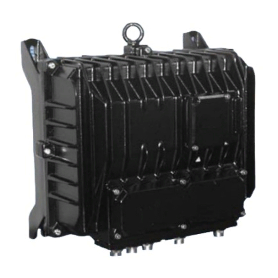
ABB EBN853 Instruction
For the control of contrac actuators in explosion-proof design
Hide thumbs
Also See for EBN853:
- Operating instructions manual (38 pages) ,
- Operating instruction (46 pages) ,
- User manual (44 pages)

Related Manuals for ABB EBN853


Summary of Contents for ABB EBN853
- Page 1 Instruction Electronic Units for Field Installation 42/68-830 EN EBN853, EBN861 (Contrac) For the control of Contrac actuators in explosion proof design...
-
Page 2: Table Of Contents
Electrical connection ......10 ..11 Wiring diagram EBN853 / EBN861 (Standard) F-Nr. / No. -
Page 3: General
3. General Proper Use Power electronic units EBN853 and EBN861 may be used exlusively for triggering electrical actuators of the RSDE... or RHDE ... series. Do not use them for any other purpose. Otherwise, a hazard of per- sonal injury or of damage to or impairment of the operational reliability of the device may arise. -
Page 4: Assemblies
6. Assemblies Power electronic units EBN853 and EBN861 consist of 2 parts each, one containing the connecting units (EBN853) and the transformer, the other containing the electronics and the local control panel (LCP) for local operation and basic actuator adjustment. -
Page 5: Ebn861
EBN861 local control panel elctronic unit (LCP) cover cover screws hinge screws transformer and power part hinge screws cover screws signal cable signal terminals power mains cable cable cable entry entry terminals (motor) motor / (r00113rxa) brake Fig. 3: EBN861 without LCP and connection chamber cover... -
Page 6: Technical Data
7. Technical Data General EBN853 EBN861 Supply voltage 115 V AC (94 V ... 130 V) or 230 V AC (190 V... 260 V); 230 V AC (190 V ... 260 V) ; 47.5 ... 63 Hz; 1Ph 47.5 ... 63 Hz; 1Ph... -
Page 7: Current Consumption Of Ebn853
Current Consumption of EBN853 115 V 230 V pos. RHDE250-10 1.8 A 0.9 A each approx 40 .. 50% of I RHDE500-10 2.2 A 1.1 A RHDE800-10 3.4 A 1.7 A RHDE1250-12 6.0 A 3.0 A RHDE2500-25 4.8 A 2.4 A RHDE4000-40 4.0 A... - Page 8 7.4.1 External fuses for EBN861 Apart from the internal fuses (see also 7.4), the EBN861 power electronic unit requires two additional external fuses, which are supplied separately to the unit. ϑ 35 A 16 A ( Electronic AC 230 V 1~ unit Fig.
-
Page 9: Mounting
- The shield of the connection cable between the electronics and the actuator must be applied to both housings. EBN853 Disconnect the electronic unit and the actuator prior to all installation and service works. - Fasten the unit to the vertical mounting plate, using screws of property class 8.8 (tensile strength 800 N/mm ;... -
Page 10: Electrical Connection
3RN1, ident no. II (2) G, PTB 01 ATEX 3218 , Siemens or type EMT6-..., ident no. II (2) G, PTB 02 ATEX 3162 , Moeller The ABB motor temperature monitoring unit SD241B may also be used for these measures. For details see instructions for electronic units for rack installation. -
Page 11: Wiring Diagram Ebn853 / Ebn861 (Standard)
Wiring diagram EBN853 / EBN861 (Standard) AC 115 / 230 V ext. fuse (EBN 861 only AC 230 V) sub distribution board SD241B screen grounded at both ends screen connection at only one end in further wiring possible setpoint transmitter act. -
Page 12: Example For Signal Input / Output
Fig. 12: Connecting the cable shield of EAN823; EBN853; EBN861 Connect the screen at the actuator accordingly. -
Page 13: Setup
10.Setup The actuator only requires the basic settings (adaptation to the operating range) in order to be operated with the standard or custumer specific configuration. Use the Local Control Panel (LCP) for these set- tings. Use the appropriate configuration software for more detailed parameter changes or diagnosis functions. -
Page 14: Adjustment Using The Configuration Program
10.1.4Setting 10.1.4.1 “Setting” mode - Set electronics to “setting” mode by pressing both push buttons (3) simultaneously for approx. 5 seconds, until both LEDs (2 + 8) are flashing synchronously at approx. 4Hz. („setting mode“ is the standard electronic unit status after passing the final factory test) 10.1.4.2 Defining first position (0% or 100%) (Higher precision in 2nd position) - Move to desired position by pressing one of the push buttons (3). -
Page 15: Alarms / Failures
11. Alarms / Failures 11.1 Definition 11.1.1 Alarms The actuator / electronic unit is exposed to critical conditions (e. g. high temperature) which currently do not affect the actuator, the electronic unit, the process or persons. The actuator functions are still available. -
Page 16: Failure Scheme
11.3 Failure scheme positioning loop hardware monitoring software monitoring monitoring frequency converter position sensor memory error - standstill end position flash error - min. speed RAM error - movem. to wrong direct. watchdog monitoring activated monitoring & Failure Signal failure message via act. -
Page 17: Troubleshooting
12. Troubleshooting This section mainly describes how to handle hardware errors. Refer to the configuration program’s on- line help for errors related to the software. Error Possible reason Measures to be taken Valve cannot be moved by actuator Malfunction of actuator or valve (e.g. Disconnect the actuator from the stuffing box tightened too much) valve. - Page 18 ABB has Sales & Customer Support The Company’s policy is one of continuous product expertise in over 100 countries worldwide.. improvement and the right is reserved to modify the information contained herein without notice. www.abb.com/instrumentation Printed in the Fed. Rep. of Germany (05.05) ©...