Available languages
Available languages
F616881
Optional PCB Installation Manual
SAFETY PRECAUTIONS
•
Read the following "SAFETY PRECAUTIONS" carefully before installation.
•
Electrical work must be installed by a licensed electrician.
•
The caution items stated here must be followed because these important contents are related to safety.
The meaning of each indication used is as below. Incorrect installation due to ignoring of the instruction will
cause harm or damage, and the seriousness is classifi ed by the following indications.
WARNING
This indication shows the possibility of causing death or serious injury.
This indication shows the possibility of causing injury or damage to properties
CAUTION
only.
The items to be followed are classifi ed by the symbols:
Symbol with white background denotes item that is PROHIBITED from doing.
Symbol with dark background denotes item that must be carried out.
•
Carry out test run to confi rm that no abnormality occurs after the installation. Then, explain to user the
operation, care and maintenance as stated in instructions. Please remind the customer to keep the
operating instructions for future reference.
1) Be sure to turn off all power supply before installing and connecting the Optional PCB. Otherwise, it
will cause electrical shock.
2) Engage authorized dealer or specialist for installation. Defective installation will cause electrical shock
or fi re.
3) Strictly follow this installation instruction when doing installation work. Defective installation will cause
electrical shock or fi re.
4) Use the attached accessories parts and specifi ed parts for installation. Otherwise, it will cause
electrical shock or fi re.
5) For electrical work, follow local national wiring standard, regulation and this installation instruction.
Otherwise, it will cause electrical shock or fi re.
6) Wire routing must be properly arranged so that control board cover is fi xed properly. If control board
cover is not fi xed properly, it will cause electrical shock or fi re.
7) Do not modify the length of Optional PCB lead wires. Otherwise, it will cause abnormal operation,
electrical shock or fi re.
8) Do not touch the Optional PCB once the power supply is turn on. Accidental contact with the Optional
PCB will cause electrical shock.
Attached Accessory
No. Accessory Part
Optional PCB (CZ-NS4P)
1
Spacer
2
Spacer
3
Electric Circuit
ROOM THERMO 2 ROOM THERMO 1
L
N
COOL HEAT
CN209
CN201
POOL
WATER
SSR202
PUMP
SIGNAL
SIGNAL
DETECTION
DETECTION
SOLAR
CIRCUIT
CIRCUIT
WATER
SSR203
PUMP
ERROR
SIGNAL
RY1
CN208
WATER
PUMP
SSR200
ZONE 1
WATER
PUMP
SSR201
ZONE 2
1
CN-CNT
CN205
CN204
(WHITE)
5
Water Circuit And System Installation
1. Functions below are available through the connection of the Optional PCB (CZ-NS4P) to the Main PCB.
•
2-zone control
•
Pool
•
Buffer tank
•
Solar
•
External error signal output
•
Demand control
•
SG ready
•
Stop compressor by external compressor switch
•
Switch heating and cooling by external Heat-Cool switch
2. Please refer to the Indoor Unit installation manual for water circuit installation details and system setup details.
Recommended Specifi cations of Field Supply Accessories
Wired
i
Room thermostat
Wireless
ii
Mixing valve
-
iii
Pump
-
iv
Buffer tank sensor
-
v
Zone water sensor
-
vi
Zone room sensor
-
vii
Solar sensor
-
WARNING
Qty. No. Accessory Part
Holder
4
1
Holder
5
Screw
6
6
16
MIXING
MIXING
VALVE 1
VALVE 2
L
N
COOL HEAT
N OPEN CLOSE
N OPEN CLOSE
W
5
CN203
1
W
CN202
3
CN-COMM
W
(YLW)
W
1
4
SIGNAL
SIGNAL
W
1
1
CN-PWR202
DETECTION
DETECTION
(YLW)
2
W
2
CIRCUIT
CIRCUIT
ACN (WHT)
BL
3
ACL (BLK)
W
1
W
1
2
CN-PWR204
2
W
(YLW)
1
3
B
DCN
3
R
(BLU)
DCP
1
(RED)
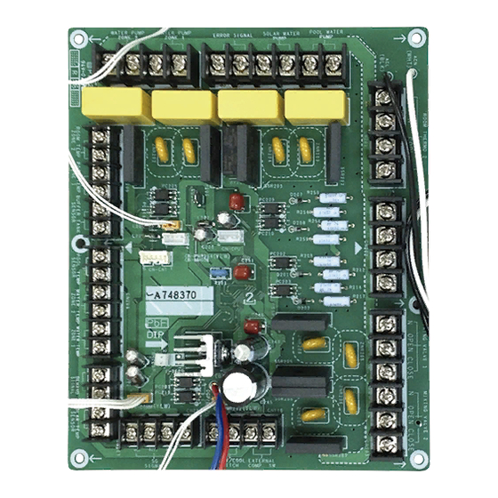
Optional PCB (CZ-NS4P)
CN207
CN206
CN210
REMARKS:
W
: WHITE
R
: RED
VCC
BIT2 BIT1
B
: BLUE
DC
DC
BL
: BLACK
GND
1OV
PAW-A2W-RTWIRED
AC230V
-
PAW-A2W-RTWIRELESS
167032
AC230V
Caleffi
Yonos 25/6
AC230V
Wilo
PAW-A2W-TSBU
-
-
PAW-A2W-TSHC
-
-
PAW-A2W-TSRT
-
-
PAW-A2W-TSSO
-
-
Optional PCB Installation
Before installing the Optional PCB, steps below need to be carried out to remove the exterior chassis.
Be sure to switch off all the power supply (i.e. indoor power supply, heater power supply, boiler
tank power supply) before performing the steps below to avoid electrical shocks, etc.
Step 1: Removal of the Cabinet Front Plate
Please follow the steps below for take out front plate. Before removing the front plate of indoor unit, always
switch off all power supply (i.e. indoor unit power supply, heater power supply and Tank Unit power supply).
1. Remove the 2 mounting screws which located at bottom of the front plate.
2. Gently pull the lower section of the front plate towards you to remove the front plate from left and right
hooks.
3. Hold the left edge and right edge of front plate to lift up front plate from hooks.
Step 2: Open the Control Board Cover
Please follow the steps below to open control board cover. Before opening the control board cover of
indoor unit, always switch off all power supply (i.e. indoor unit power supply, heater power supply and Tank
Unit power supply).
1. Remove the 6 mounting screws at the control board cover.
2. Swing the control board cover to the right hand side.
Step 3: Installing the Optional PCB 1 onto the Control Board
Qty.
1. Refer to the fi gures below, tighten Holder 4 and Holder 5 onto the control board with Screw 6 .
2. Fix the Spacer 2 and Spacer 3 onto the control board. Then fi x and push to hook the Optional PCB onto
5
the Spacer 2 and Spacer 3 .
Spacer
5
4
Holder
- 5pcs
6
10
Screw
- 5pcs
CN-CNT
(WHT)
MAIN
PCB
CN-PWR2
(BLU)
CN-PWR (BLK)
CN-PWR4
(BLK)
CN-PWR3
(GRN)
Step 4: Connecting Optional PCB 1 lead wires to the Main PCB
1. Connect the lead wires from ACN (WHT) & ACL (BLK) (from Optional PCB 1 ) to CN-PWR (BLK) (from
Main PCB).
2. Connect the lead wires from CN-COMM (YLW) (from Optional PCB 1 ) to CN-CNT (WHT) (from Main
PCB).
3. Connect the lead wires from CN-PWR202 (YLW) (from Optional PCB 1 ) to CN-PWR2 (BLU) (from
Main PCB).
4. Connect the lead wires from CN-PWR204 (YLW) (from Optional PCB 1 ) to CN-PWR4 (BLK) (from
Main PCB).
5. Connect the lead wires from DCN (BLU) & DCP (RED) (from Optional PCB 1 ) to CN-PWR3 (GRN)
(from Main PCB).
6. Make sure all connections are fi xed securely.
7. Guide all lead wires as shown in the fi gures below.
ACN(WHT)
DCN(BLU)
DCP(RED)
CN-PWR204 (YLW)
Main PCB
CN-PWR2 (BLU)
CN-PWR3 (GRN)
CN-PWR (BLK)
WARNING
Hook
Lift up
Screws
CAUTION
Screws
Screws
2
- 6pcs
Control
Board
5
Holder
- 5pcs
6
Screw
- 5pcs
1
Optional PCB
Make sure holes of
1
Optional PCB
(6 locations) are
fully insert into the
Push to
2
Spacer
hook
ACL (BLK)
CN-PWR202 (YLW)
1
Optional PCB
CN-COMM (YLW)
CN-PWR2 (BLU)
CN-PWR4 (BLK)
CN-PWR (BLK)
*For WH-SDC03H3E5 and WH-SDC05H3E5 only
CN-PWR4 (BLK)
CN-CNT (WHT)
3
Spacer
- 16pcs
2
Spacer
Optional
1
PCB
Main PCB
CN-PWR3 (GRN)
CN-CNT (WHT)
ENGLISH
1
F616881
14
PRINTED IN MALAYSIA
Table of Contents

Summary of Contents for Panasonic CZ-NS4P
- Page 1 6. Make sure all connections are fi xed securely. Water Circuit And System Installation 7. Guide all lead wires as shown in the fi gures below. 1. Functions below are available through the connection of the Optional PCB (CZ-NS4P) to the Main PCB. ACN(WHT) ACL (BLK) CN-PWR202 (YLW) •...
- Page 2 6. Asegúrese de que todas las conexiones están fi jadas con fi rmeza. 1. Las funciones de abajo están disponibles a través de a conexión de la placa base opcional (CZ-NS4P) a 7. Guíe todos los cables como se muestra en las fi guras de abajo.
- Page 3 6. Fare in modo che tutti i collegamenti siano installati in modo sicuro. 1. Le funzioni di seguito sono disponibili tramite il collegamento della PCB opzionale (CZ-NS4P) alla PCB 7. Guidare tutti i fi li come mostrato nelle fi gure di seguito.
- Page 4 6. Zorg ervoor dat alle aansluitingen goed vast zitten. 7. Geleid en bevestig de draden zoals in de afbeelding hieronder aangegeven. 1. De functies hieronder zijn beschikbaar via de aansluiting van het optionele PCB (CZ-NS4P) op de hoofdprintplaat. • ACN(WHT)
- Page 5 6. Należy upewnić się, że wszystkie połączenia są dobrze zamocowane. Montaż obwodu wodnego i systemu 7. Wszystkie przewody należy poprowadzić w sposób przedstawiony na poniższych ilustracjach. 1. Poniższe funkcje są dostępne po podłączeniu opcjonalnej płyty głównej (CZ-NS4P) do podstawowej płyty głównej. ACN(WHT) ACL (BLK) CN-PWR202 (YLW) •...
- Page 6 F616881 Βεβαιωθείτε ότι αποσυνδέσατε όλες τις τροφοδοσίες ρεύματος (δηλ. τροφοδοσία ρεύματος αντλίας ΠΡΟΦΥΛΑΞΕΙΣ ΑΣΦΑΛΕΙΑΣ θέρμανσης, τροφοδοσία ρεύματος θερμαντήρα, τροφοδοσία ρεύματος δεξαμενής λέβητα) πριν εκτελέσετε τα παρακάτω βήματα για να αποφύγετε ηλεκτροπληξίες, κ.λπ. • • • • N OPEN CLOSE N OPEN CLOSE COOL HEAT COOL HEAT CN209...
- Page 7 6. Ujist te se, zda jsou všechny spoje bezpe n upevn ny. 7. Ve te všechny vodi e podle níže uvedených obrázk . 1. Níže uvedené funkce jsou k dispozici v p ípad p ipojení volitelné ídicí desky (CZ-NS4P) ke hlavní ídicí desce.
- Page 8 6. Assurez-vous que toutes les connexions sont bien fi xées. 1. Les fonctions ci-dessous sont disponibles via la connexion de la carte optionnelle (CZ-NS4P) à la carte 7. Guidez tous les fi ls comme illustré dans les fi gures ci-dessous.
- Page 9 Installation des Wasserkreislaufs und des Systems 6. Vergewissern Sie sich über den festen Anschluss aller Kabelverbindungen. 7. Führen Sie alle Hauptkabel wie in den Bildern unten dargestellt. 1. Die Funktionen unten sind über die Verbindung der optionalen Platine (CZ-NS4P) zur Hauptplatine verfügbar. • ACN(WHT)
- Page 10 7. Tüm kablo tellerini a a õdaki ekilde gösterildi i gibi yönlendirin. Su Devresi ve Sistem Kurulumu ACN(WHT) ACL (BLK) CN-PWR202 (YLW) 1. A a õdaki i levler ste e Ba lõ PCB (CZ-NS4P) ba lantõsõndan Ana PCB’ye kullanõlabilir. • ste e Ba lõ PCB 2 bölgeli kontrol •...
- Page 11 6. Se till så att alla anslutningar är säkert fastgjorda. 7. Led alla ledningskablar så som visas på bilderna nedan. Vattenkrets- och systeminstallation ACN(WHT) ACL (BLK) CN-PWR202 (YLW) 1. Funktionerna nedan är tillgängliga genom anslutning av tilläggskortet (CZ-NS4P) till huvudketskortet. Tilläggskort • 2-zonskontroll Huvudkretskort CN-COMM (YLW) •...
- Page 12 6. Sørg for at alle tilkoblingene er godt festet. Montering av vannrør og system 7. Før alle ledningene som vist i fi gurene under. 1. Funksjonene nedenfor er tilgjengelige ved tilkobling av alternativt kretskort (CZ-NS4P) til hovedkretskortet. ACN(WHT) ACL (BLK) CN-PWR202 (YLW) •...
- Page 13 6. Tarkista, että kaikki liitännät ovat kiinni tukevasti. 7. Reititä johdot kuten alla olevissa kuvissa. Vesikierron ja järjestelmän asentaminen ACN(WHT) ACL (BLK) CN-PWR202 (YLW) 1. Alla mainitut toiminnot ovat käytettävissä asentamalla valinnainen piirikortti (CZ-NS4P) pääpiirikorttiin. • Valinnainen piirikortti 2 alueen hallinta • Uima-allas Pääpiirikortti...
- Page 14 7. Før alle ledningerne som vist i fi gurerne nedenfor. Vandkreds og systeminstallation ACN(WHT) ACL (BLK) CN-PWR202 (YLW) 1. Funktioner nedenfor er tilgængelige via tilslutning af det ekstra printkort (CZ-NS4P) til hovedprintkortet. Ekstra printkort • 2 zone kontrol Hovedprintkort CN-COMM (YLW) •...