
Related Manuals for Samsung MIM-B16N


Summary of Contents for Samsung MIM-B16N
- Page 1 PIM(Pulse Input Module) MIM-B16N Air Conditioner installation manual imagine the possibilities Thank you for purchasing this Samsung product.
-
Page 2: Table Of Contents
Contents Before installation Safety Precautions . . . . . . . . . . . . . . . . . . . . . . . . . . . . . . . . . . . . . . . . . . . . . . . . . . . . . . . . . . . . . . . . . . . . . . . . . . . . . . . . . . . . . . . . . . . . . . . . . . . . . . . . . . 3 Accessories . -
Page 3: Safety Precautions
Safety Precautions This installation manual describes how to install the PIM . For installation of other optional accessories, refer to the appropriate installation manual . WARNING Hazards or unsafe practices that may result in severe personal injury or death. CAUTION Hazards or unsafe practices that may result in minor personal injury or property damage. -
Page 4: Accessories
Accessories Make sure you have each item . Supplied items may vary depending on your country or service provider . The type and quantity may differ depending on the specifications . Installation Item Adapter Power cable M4x16 Screw Cable tie manual Quantity Shape... -
Page 5: Viewing The Parts
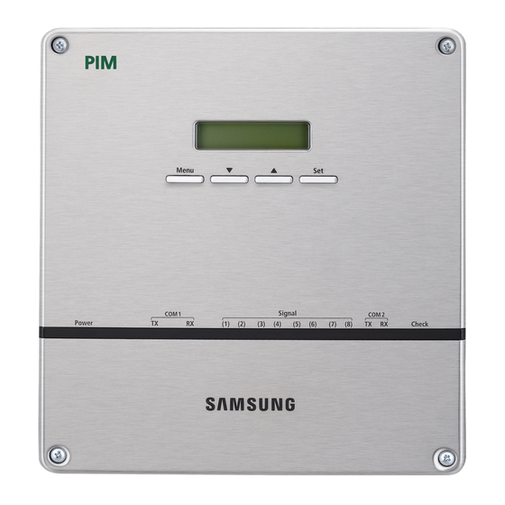
Viewing the Parts Main Parts PIM Exterior lCD Display Shows current time and consumption by channel . Various menus will be displayed depending on button input . lCD Operation button There are 4 buttons [Menu, ▼(Down), ▲(Up), Set] and you can access, move and check the menu . lED Indicator Checks the status using 14 LEDs such as Power, COM1 TX/RX, Signal, COM2 TX/RX and Check . - Page 6 Viewing the Parts PIM Cable Connection Part Pulse input terminal Pulse input terminal RS485 communication terminal (Channel 1~4) (Channel 5~8) (COM1, COM2) Cable groove Power terminal Reset button Name Description Terminal that the pulse from Meter is inputted Pulse input terminal (Channel1~Channel8) (CH1~CH8) ❇...
- Page 7 PIM Interior LED Display board 20-pin cable Main board 40-pin cable Sub board Product Dimensions 64 . 8 (Unit : mm) English-7...
-
Page 8: Pim System Architecture
PIM System Architecture Pulse input ROOM 0 ROOM 1 ROOM 2 Meter Outdoor Unit Meter (max . 8 units) f Maximum 8 PIM units can be connected to DMS . f Maximum 8 meter(Power/Gas/Water) can be connected to PIM . English-8... -
Page 9: Installing The Pim
Installing the PIM Installing the PIM on the Wall 1 . Separate the installation plate on the rear side of PIM . 2 . Fix the installation plate on the wall using 4 screws . 3 . Hang the PIM on the groove which is on the top of the installation plate . Installation plate 4 . - Page 10 Installing the PIM Connecting a Meter, PIM and DMS Connecting a Meter and PIM 1 . Unfasten the 2 screws on the bottom of the PIM front cover . Hold the bottom 2 sides of the PIM and push downwards to slide open the cover . 2 .
- Page 11 Connectable Meter with PIM Meter without Separate External Output f If the pulse constant(Wh/Pulse or m /Pulse or L/Pulse) value is an integer, connection is possible . e . g . Pulses per kWh : 1,000 converted to 1Wh/Pulse, Connection is possible! e .
- Page 12 Installing the PIM Connecting PIM to DMS 1 . Connect ‘COM1’ terminal of PIM and DMS terminal block with communication cable . - Pay special attention about the polarity when connecting RS485 communication . (A of PIM ↔ A of DMS, B of PIM ↔ B of DMS) Connect Connect communication...
- Page 13 f If PIM is connected to DMS, PIM setting through DMS web is possible . English-13...
- Page 14 Installing the PIM Installing more than 2 PIM Units to 1 DMS 1 . Unfasten the 2 screws on the top of the PIM . Hold the top 2 sides of the PIM and pull it the cover upwards to open the cover . 2 .
-
Page 15: Setting The Pim
Setting the PIM Setting the PIM(Mandatory) It is mandatory when you connect Meter and PIM . Setting the Password 2.1Password Set your P/W Password Set : : : Main menu → 2 . Configuration → 2 . 1 Password . f Default : 0000 f For the further information, refer to page 20 . -
Page 16: Pim Menu Description
PIM Menu Description Menu Configuration Normal Display 1. Monitoring 1.1 Address 1.2 Option S/W Current Time 1.3 Micom Ver. CH1: 00000.0kWh 1.4 DB Code CH2: 00000.0kWh 2. Configuration 2.1 Password CH8: 00000.0kWh 2.2 Meter Type Displayed repeatedly 2.3 Pulse Rate 2.4 Date&Time 2.5 Channel Use 2.6 Value Set... - Page 17 Normal Display 1 . When the power is connected, current PIM address and software version will be displayed . - Example display: PIM address 58 30 FF Software version DB91-01128A - “Address:58 30 FF” is an example . It is subject to change according to the setting . Device Info.
- Page 18 PIM Menu Description Monitoring Menu Address 1 . Access to main menu by pressing the [Menu] button from the normal display . Then select ‘1 . M onitoring’ by pressing the [Set] button . Main Menu 1.Monitoring 2 . To check the Address, press the [Set] button when ‘1 . 1 Address’ appears . 1.Monitoring 1.1 Address 1.1 Address...
- Page 19 Micom Version 1 . Access to main menu by pressing the [Menu] button from the normal display . Then select ‘1 . M onitoring’ by pressing the [Set] button . Main Menu 1.Monitoring 2 . To check the Micom Version, press the [Set] button when ‘1 . 3 Micom Ver . ’ appears . 1.Monitoring 1.3 Micom Ver.
- Page 20 PIM Menu Description Configuration menu Setting the Password f You should enter the password to use Configuration menu . Password Set 1 . Access to main menu by pressing the [Menu] button from the normal display . Then select ‘2 . C onfiguration’ by pressing the [], [] buttons, and press the [Set] button .
- Page 21 Password Reset 1 . Access to main menu by pressing the [Menu] button from the normal display . Then select ‘2 . C onfiguration’ by pressing the [], [] buttons, and press [Set] button . Main Menu 2.Configuration 2 . Enter the password using the [], [] buttons and press the [Set] button . - The default password is ‘0000’...
- Page 22 PIM Menu Description Setting the Meter Type f You can set the meter type . 1 . Access to main menu by pressing the [Menu] button from the normal display . Then select ‘2 . C onfiguration’ by pressing the [], [] buttons, and press the [Set] button . Main Menu 2.Configuration 2 .
- Page 23 Setting the Pulse Rate f You can set the pulse constant (Wh/Pulse or m /Pulse or L/Pulse) value of the meter connected to each channel . 1 . Access to main menu by pressing the [Menu] button from the normal display . Then select ‘2 . C onfiguration’ by pressing the [], [] buttons, and press the [Set] button .
- Page 24 PIM Menu Description Setting the Date and Time Date setting 1 . Access to main menu by pressing [Menu] button from the normal display . Then select ‘2 . C onfiguration’ by pressing the [], [] buttons, and press [Set] button . Main Menu 2.Configuration 2 .
- Page 25 Time setting 1 . Access to main menu by pressing [Menu] button from the normal display . Then select ‘2 . C onfiguration’ by pressing the [], [] buttons, and press [Set] button . Main Menu 2.Configuration 2 . Enter the password using the [], [] buttons and press the [Set] button . - The default password is ‘0000’...
- Page 26 PIM Menu Description Setting the Enable/Disable Status of Channel f Enable/Disable the 8 pulse input channels . 1 . Access to main menu by pressing the [Menu] button from the normal display . Then select ‘2 . C onfiguration’ by pressing [], [] buttons, and press the [Set] button .
- Page 27 Setting the Initial Value f You can set the initial value for each channel . 1 . Access to main menu by pressing the [Menu] button from the normal display . Then select ‘2 . C onfiguration’ by pressing the [], [] buttons, and press the [Set] button . Main Menu Enter your P/W 2.Configuration...
- Page 28 PIM Menu Description Initializing the usage value for each channel 1 . Access to main menu by pressing the [Menu] button from the normal display . Then select ‘2 . C onfiguration’ by pressing the [], [] buttons, and press the [Set] button . Main Menu 2.Configuration 2 .
- Page 29 Check Menu Pulse Input Status Check f You can check the status of pulse which is input to each channel . 1 . Access to main menu by pressing the [Menu] button from the normal display . Then select ‘3 . Check’ by pressing the [], [] buttons, and press [Set] button .
- Page 30 PIM Menu Description Check the RS485 Circuit of PIM itself for Test or Service f You can check if the RS485 circuit is normal when you have doubt the main board . f Before checking, connect COM1 and COM2 terminal with wire as you see the right figure . 1 .
- Page 31 Checking the Pulse Width Setting Error f It checks if the pulse width setting for each channel and the pulse width of actually connected Meter are same or not . 1 . Access to main menu by pressing the [Menu] button from the normal display . Then select ‘3 . Check’ by pressing the [], [] buttons, and press the [Set] button .
- Page 32 DB68-04502A-03...