Quick Links
OptiX RTN PI-DC A11
Product Overview and Installation Guide
Issue: 04
Date: 2018-10-30
HUAWEI TECHNOLOGIES CO., LTD .
Copyright © Huawei Technologies Co., Ltd. 2018. All rights reserved.
No part of this document may be reproduced or transmitted in any form or by any means without prior
written consent of Huawei Technologies Co., Ltd.
Huawei Technologies Co., Ltd.
Address: Huawei Industrial Base
Bantian, Longgang
Shenzhen 518129
People's Republic of China
Website:
http://www.huawei.com
Email:
Safety Precautions
• Always hold an insulated part of the P&E cable. Never touch the RJ45 connector.
• Do not touch the pins inside the P&E port on the PI with your hands or a conductor.
• Be sure to connect the power cables of the PI correctly to the positive and negative terminals of the power supply
device .To prevent damage to power cables or devices caused by short-circuits, install a circuit breaker on the
negative terminal of the power supply device.
• Do not install or remove a live P&E cable.
01

Related Manuals for Huawei PI-DC A11

Summary of Contents for Huawei PI-DC A11
- Page 1 • Do not install or remove a live P&E cable. HUAWEI TECHNOLOGIES CO., LTD . Copyright © Huawei Technologies Co., Ltd. 2018. All rights reserved. No part of this document may be reproduced or transmitted in any form or by any means without prior written consent of Huawei Technologies Co., Ltd.
-
Page 2: Product Overview
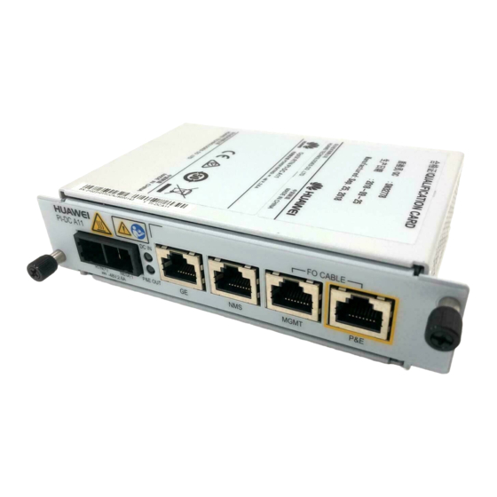
Product Overview The RTN PI-DC A11 is an indoor PI. It uses DC power input and transmits GE electrical signals and -48 V power signals to the full-outdoor RTN 300 equipment through an outdoor network cable. Appearance and Ports Port Description... - Page 3 Principles Application Scenarios The RTN PI-DC A11 receives one channel of DC power signals and one channel of GE service signals. The RTN PI-DC A11 can supply power to OptiX RTN 300 full-outdoor microwave equipment series. The power supply mode of the PI varies according to powered device type.
-
Page 4: Technical Specifications
Product Overview Technical Specifications Power Supply Electromagnetic Compatibility and Safety Compliance Item Description Item Description DC input, with the voltage ranging from –38.4 V to –57.6 V •Passed CE authentication. Input voltage •Compliant with ETSI EN 301 489-1. Electromagnetic compatibility •Compliant with ETSI EN 301 489-4. - Page 5 Installation Guide Terminating a DC Output Power Cable with a Connector Strip a power cable based on the stripping Use a screwdriver to poke the cable locking indicator. latches out. 12 mm 10 mm 10 mm NOTE For the stripping length, see the stripping indicator on the PI. Push the cable locking latches on both sides Insert the power cable.
- Page 6 Installation Guide Installing the PI in a 19-Inch Cabinet Installing the PI in an ETSI Cabinet Fix the floating nuts. Insert the PI into a slot on the auxiliary mounting bracket and tighten the Insert the PI into a slot on the auxiliary mounting captive screws on the mounting ears.
- Page 7 Installation Guide Installing the PI in an Outdoor Cabinet Installing the PI on a Wall Mark and drill holes in the wall. Install the PI in an outdoor cabinet. Install the mounting ears. Hold the PI up to the wall and mark the drilling positions.
-
Page 8: Install Cables
Installation Guide Install cables Install the P&E cable of the PI. Arrange indoor PI cables. NOTE If two or three PIs are installed on one auxiliary installation bracket, cables of the PIs should be arranged to meet the requirements of the site. Generally, power cables are routed along the left side in the cabinet and service cables are routed Connect to the P&E port on the device.