Yamaha EF3000iSE, EF3000iSEB Owner's Manual
Yamaha generator owner's manual
Hide thumbs
Also See for EF3000iSE, EF3000iSEB:
- Installation manual ,
- Service manual (327 pages) ,
- Owner's manual (148 pages)
Table of Contents
Table of Contents

Related Manuals for Yamaha EF3000iSE, EF3000iSEB


Summary of Contents for Yamaha EF3000iSE, EF3000iSEB
- Page 1 Generator OWNER’S MANUAL EF3000iSE EF3000iSEB LIT-19626-01-20 7CH-28199-10...
- Page 3 AE00002 Congratulations on your purchase of your new Yamaha. This manual will provide you with a good basic understanding of the operation and main- tenance of this machine. If you have any questions regarding the operation or maintenance of your machine, please consult a Yamaha dealer.
- Page 4 NOTE: 9 Yamaha continually seeks advance- ments in product design and quality. Therefore, while this manual contains the most current product information available at the time of printing, there may be minor discrepancies between your engine and this manual. If there is any question concerning this manual, please consult your Yamaha dealer.
-
Page 5: Table Of Contents
AE00041 CONTENTS LIMITED WARRANTY (EF- AND EDL-SERIES)...1 LOCATION OF IMPORTANT LABELS ..3 SAFETY INFORMATION ...5 EXHAUST FUMES ARE POISONOUS ...5 FUEL IS HIGHLY FLAMMABLE AND POISONOUS ...5 ENGINE AND MUFFLER MAY BE HOT...5 ELECTRIC SHOCK PREVENTION...6 CONNECTION NOTES ...7 CONNECTION...7 EXTENSION CORD NOTES ...7 CONTROL FUNCTION ...8 DESCRIPTION ...8... -
Page 6: Limited Warranty (Ef- And Edl-Series)
DURING THE PERIOD OF WARRANTY any authorized Yamaha consumer generator dealer will, free of charge, repair or replace, at Yamaha’s option, any part adjudged defective by Yamaha due to faulty workmanship or material from the factory. Parts used in warranty repairs will be warranted for the balance of the product’s warranty period. - Page 7 Q. Will the warranty be void or cancelled if I do not operate or maintain my new Yamaha exactly as specified in the Owner’s Manual? A. No. The warranty on a new Yamaha cannot be “voided” or “cancelled.” However, if a particular failure is caused by operation or maintenance other than as shown in the Owner’s Manual, that failure...
-
Page 8: Location Of Important Labels
AE00062 LOCATION OF IMPORTANT LABELS Please read the following labels carefully before oper- ating this machine. NOTE: Maintain or replace safety and instruction labels, as necessary. 792-052c 792-053c – 3 –... - Page 9 MACHINE AU SEC EN TOUTES CIRCONSTANCES. – 4 – zzzzzz Single Gasoline YAMAHA MOTOR CO., LTD. MADE IN JAPAN ***-24164-** ENGINE AIR INDEX ( C a l i f o r n i a onl y ) INTERMEDIATE CHECK OWNERS MANUAL FOR FURTHER D E T A I L S YAMAHA MOTOR CO.
-
Page 10: Safety Information
AE00071 SAFETY INFORMATION AE00072 EXHAUST FUMES ARE POISONOUS 9 Never operate the engine in a closed area or it may cause unconsciousness and death within a short 741-092 time. Operate the engine in a well ventilated area. AE00075 FUEL IS HIGHLY FLAMMABLE AND POISONOUS 9 Always turn off the engine when refuelling. -
Page 11: Electric Shock Prevention
741-098 741-099 741-100 741-101 741-102 741-103b 9 Keep the machine at least 1 m (3 ft) from buildings or other equipment, or the engine may overheat. a 1 m (3 ft) 9 Avoid operating the engine with a dust cover. 9 Be sure to carry the generator only by its carrying handle(s). -
Page 12: Connection Notes
Ground (earth) Lead Diameter: 0.12 mm (0.005 in)/ampere 10 Ampere → 1.2 mm (0.05 in) AE00088 CONNECTION NOTES 9 Avoid connecting the generator to commercial power outlet. 9 Avoid connecting the generator in parallel with any other generator. 1 Correct 2 Incorrect AE00091 CONNECTION... -
Page 13: Control Function
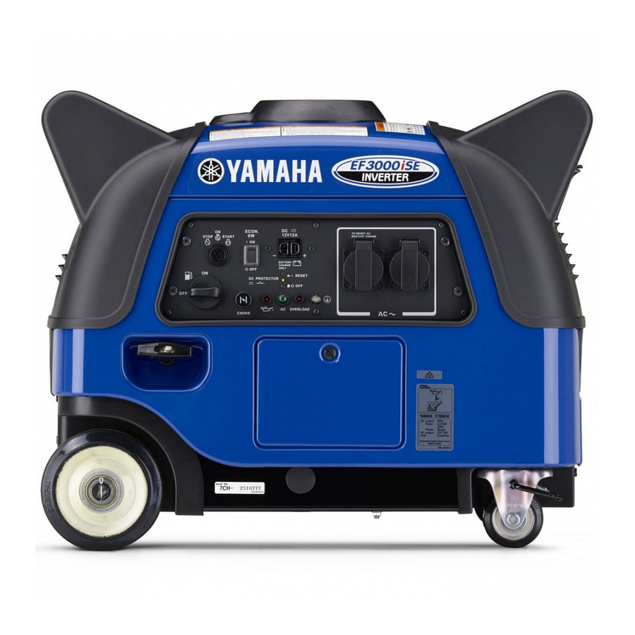
AE00101 CONTROL FUNCTION 793-107c 793-108c o i u – 8 – AE00102 DESCRIPTION 1 Recoil starter 2 Oil filler cap 3 Oil drain plug 4 Battery box/Battery 5 Carrying handles (shaded) 6 Muffler 7 Fuel tank cap AE00103 CONTROL PANEL 1 Engine switch 2 Economy control switch 3 DC receptacle... -
Page 14: Oil Warning System
700-121 763-119 AE00111 OIL WARNING SYSTEM When the oil level falls below the lower level, the engine stops automatically. Unless you refill with oil, the engine will not start again. NOTE: If the engine stalls or does not start, turn the engine switch to “ON”... -
Page 15: Economy Control Switch
The DC protector turns off automatically when the load exceeds the generator rated output. 763-231 Reduce the load to the specified generator rated output if the DC protector turns off. If it turns off again, consult a Yamaha dealer. NOTE: Press to reset the DC protector. 763-238a AE01048... -
Page 16: Pre-Operation Check
FUEL Make sure there is sufficient fuel in the tank. 707-033a Your Yamaha engine has been designed to use regular unleaded gasoline with a pump octane number ((R + M)/2) of 86 or higher, or research octane number of 91 or higher. -
Page 17: Engine Oil
700-122 700-103c 0°C 25°C A YAMALUBE 4(10W-30) D SAE 10W C SAE #20 B SAE #30 32°F 80°F 700-006 741-106b AE00222 ENGINE OIL Make sure the engine oil is at the upper level of the oil filler hole. Add oil as necessary. 1 Upper level Recommended oil: å... -
Page 18: Battery
788-006 788-007 762-044 762-045 EF3000iSEB to STARTER RELAY to ENGINE to DC-DC CONVERTER 762-045a AE01083 BATTERY (See page 30) Installation 1. Loosen the bolts 1 and remove the cover 2. 2. Loosen the bolts 3 and remove the battery box 4. 3. - Page 19 788-007a 788-006a 762-012 8. Secure it with the band. 9. Install the battery box 5 and tighten the bolts 6. 10. Install the cover 7 and tighten the bolts 8. Battery electrolyte is poisonous and dangerous, causing severe burns, etc. It contains sulfuric (sul- phuric) acid.
-
Page 20: Operation
700-006a 761-080 763-126b 705-073 701-049b 763-120e AE00955 OPERATION NOTE: The generator has been shipped without engine oil. Fill with oil or it will not start. 1 Upper level AE01073 STARTING THE ENGINE NOTE: 9 Before starting the engine, do not connect any electric devices. - Page 21 9 Take your hand off the switch immediately after 9 If the engine fails to start, release the switch, 4. After the engine starts, warm up the engine until 5. Push the choke knob back to the original position. NOTE: When starting the engine in areas where the ambient temperature is below 0°C (32°F), the engine automati- cally operates at the rated r/min (3,800 r/min) for three...
-
Page 22: Application Range
AE01000 APPLICATION RANGE Power factor EF3000iSE –2,800W EF3000iSEB Be sure the total load is within generator rated output otherwise generator damage will occur. NOTE: Some precision equipment is voltage sensitive and may require a more uniform voltage supply than portable generators provide. Examples include some medical equipment, personal computers, and some inverters that sense peak and RMS voltage values. -
Page 23: Connection
AE01023 CONNECTION Alternating Current (AC) 9 Be sure all electric devices including the lines and plug connections are in good condition before connection to the generator. 9 Be sure any electric devices are turned off before plugging it in. 9 Be sure the total load is within generator rated output. -
Page 24: Overload Indicator Light
AE01087 Overload indicator light The overload indicator light 1 comes on when an over- load of a connected electrical device is detected, the inverter control unit overheats, or the AC output voltage rises. The electronic breaker will then activate, stopping power generation in order to protect the generator and 760-026 any connected electric devices. - Page 25 9 Reduce the load to the specified generator rated output if the DC protector turns off. If it turns off again, consult a Yamaha dealer. NOTE: Press to reset the DC protector. 1 “ON”...
- Page 26 Never smoke or make and break connections at the battery while charging. Sparks may ignite the bat- tery gas. Battery electrolyte is poisonous and dangerous, causing severe burns, etc. contains sulfuric (sul- phuric) acid. Avoid contact with skin, eyes or cloth- ing.
-
Page 27: Stopping The Engine
763-126b 761-080 763-120b 705-073a AE01050 STOPPING THE ENGINE NOTE: 9 Turn off any electric devices. 9 Turn the economy control switch to the “3” (OFF) position. 3 “OFF” 1. Disconnect any electric devices. 2. Turn the engine switch to the “5” (STOP) position. 5 “STOP”... -
Page 28: Periodic Maintenance
2.* Valve Clearance 3.* Crankcase breather system Idle speed Exhaust System Engine Oil Air Filter * : It is recommended that these items be serviced by a Yamaha dealer. ** : Related to emission control system. PERIODIC MAINTENANCE Pre-Ope- ration Remarks check (daily) Check condition. - Page 29 Fittings/ 15.* Fasteners * : It is recommended that these items be serviced by a Yamaha dealer. ** : Related to emission control system. Use only Yamaha specified genuine parts for replacement. Ask an authorized Yamaha dealer for further attention.
-
Page 30: Spark Plug Inspection
7. Install the side cover and tighten the bolt. AE00431 CARBURETOR ADJUSTMENT The carburetor is a vital part of the engine. Adjusting should be left to a Yamaha dealer with the professional knowledge, specialized data, and equipment to do so properly. – 25 –... -
Page 31: Engine Oil Replacement
788-004a 700-123b 700-006a 0°C 25°C A YAMALUBE 4(10W-30) D SAE 10W C SAE #20 B SAE #30 32°F 80°F 700-065 AE01074 ENGINE OIL REPLACEMENT 1. Place the machine on a level surface and warm up the engine for several minutes. Then stop the engine. -
Page 32: Muffler Screen And Spark Arrester
788-005 711-072a 711-073 711-074 711-075 AE01075 MUFFLER SCREEN AND SPARK ARRESTER The engine and muffler will be very hot after the engine has been run. Avoid touching the engine and muffler while they 741-105 are still hot with any part of your body or clothing during inspection or repair. -
Page 33: Air Filter
711-076 711-077 788-013 710-061a 6. Check the muffler screen and spark arrester. Replace them if damaged. 7. Install the spark arrester. NOTE: Align the spark arrester projection with the hole in the muffler pipe. 1 Projection 2 Hole 8. Install the muffler screen and the muffler cap. AE01084 AIR FILTER 1. -
Page 34: Fuel Tank Filter
Do not wring out the element. This could cause it to tear. 6. Insert the element into the air filter. 710-062 NOTE: Be sure the element sealing surface matches the air fil- ter so there is no air leak. The engine should never run without the element; excessive piston and cylinder wear may result. -
Page 35: Battery
To charge the battery Have a Yamaha dealer charge the battery as soon as possible if it seems to have discharged. To charge a sealed-type (MF) battery, a special (constant-voltage) battery charger is required. -
Page 36: Fuse Replacement
1. Remove the side cover 1 and the battery box 2. (See page 30; “BATTERY”.) 788-008 2. Replace the blown fuse with one of proper amper- age. Specified fuse: 10 A NOTE: If the fuse immediately blows again, consult a Yamaha dealer. 779-070a – 31 –... -
Page 37: Troubleshooting
707-100 705-073b 700-006 763-120g 760-009 AE01078 TROUBLESHOOTING Engine won’t start 1. Fuel systems No fuel supplied to combustion chamber. 2 No fuel in tank ... Supply fuel. 2 Fuel in tank ... Fuel cock knob to “ON”. 2 Clogged fuel line ... Clean fuel line. 2 Clogged carburetor ... - Page 38 Check engine oil level. Consult a Add engine oil. Yamaha dealer. Check the spark plug. 9 Type: 9 Gap: Incorrect Replace or Clean the spark Adjust Gap. plug. Clean or Replace; Consult Yamaha dealer. Consult a Yamaha dealer. Level low...
-
Page 39: Storage
707-102a 712-028a 712-029b AE00601 STORAGE Long term storage of your machine will require some preventive procedures to guard against deterioration. AE01056 DRAIN THE FUEL 1. Remove the fuel tank cap. Drain the fuel from the fuel tank into an approved gasoline container using a commercially available hand siphon. -
Page 40: Battery
AE01086 BATTERY 1. Remove the battery. 2. Store the battery in a cool, dark and dry place and charge it once a month. Do not store the battery in an excessively warm or cold 762-003 place [i.e., less than 0°C (30°F) or more than 30°C (90°F)]. -
Page 41: Exhaust Emission Control System And Components
The acronyms conform to the latest version of the SAE’s recommended practice docu- ment J1930, “Diagnostic Acronyms, Terms, and Definitions For Electrical/Electronic System”. It is recommended that these items be serviced by a Yamaha dealer. Acronym CYLINDER1 Ventilation) – 36 –... -
Page 42: Specifications
AE00701 AE00702 DIMENSIONS Overall Length Overall Width Overall Height Dry Weight AE00704 ENGINE Type Cylinder Arrangement Displacement Bore × Stroke Rated Output Operation Hours at rated operation Fuel Fuel Tank Capacity Engine Oil Quantity Ignition System Spark Plug: Type Spark Plug: Noise Level* : Measured at rated operation from 7 m (23 ft) distance. -
Page 43: Wiring Diagram
AE00751 WIRING DIAGRAM EF3000iSE 1 Main coil 2 Sub coil 3 DC coil 4 DC rectifier 5 Control unit 6 AC pilot light 7 AC receptacle 8 Ground (Earth) terminal 9 Economy control switch 0 Overload indicator light q DC receptacle w DC protector (breaker) e Engine switch r Oil warning light... -
Page 44: Spark Plug
AE00751 WIRING DIAGRAM EF3000iSEB 1 Main coil 2 Sub coil 3 DC coil 4 DC rectifier 5 Control unit 6 AC pilot light 7 AC receptacle 8 Ground (Earth) terminal 9 Economy control switch 0 Overload indicator light q DC receptacle w DC protector (breaker) e Engine switch r Oil warning light... - Page 45 PRINTED IN JAPAN 06 – 0.4 × 1 PRINTED ON RECYCLED PAPER...