Table of Contents
Quick Links
See also:
Service Manual
Table of Contents

Related Manuals for Yamaha AD824


Summary of Contents for Yamaha AD824
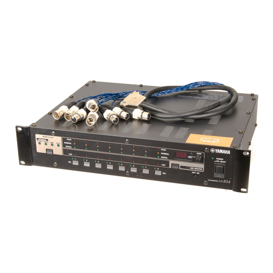
- Page 1 AD CONVERTER Owner’s Manual WORD CLOCK PEAK INTERNAL NOMINAL 44.1kHz 48kHz SLOT SIGNAL +48V Keep This Manual For Future Reference. PEAK GAIN POWER NOMINAL SIGNAL +48V +48V MASTER OFF ON AD CONVERTER...
- Page 2 300 ohm ribbon lead, change the lead-in to coaxial type cable. If these corrective measures do not produce satisfactory results, please contact the local retailer authorized to distribute this type of product. If you can not locate the appropriate retailer, please contact Yamaha Corporation of America, Electronic Service Division, 6600 Orangethorpe Ave, Buena Park, CA 90620 The above statements apply ONLY to those products distributed by Yamaha Corporation of America or its subsidiaries.
-
Page 3: Important Information
• Do not subject the AD824 to extreme temperatures, humidity, direct sunlight, or dust, which could be a potential fire or electrical shock hazard. • Do not allow water to enter the AD824 or allow it to become wet. Fire or electrical shock may result. -
Page 4: Package Contents
• Turn off all equipment before connecting it to the AD824, and use only the cables spec- ified in the relevant owner’s manuals. • If you plan not to use the AD824 for a long period of time, remove the power cord from the AC outlet. Leaving the AD824 connected is a potential fire hazard. - Page 5 Copyright No part of the AD824 software or this Owner’s Manual may be reproduced or distrib- uted in any form or by any means without the prior written authorization of Yamaha Corporation.
-
Page 6: Table Of Contents
Controlling the AD824 Remotely ........ -
Page 7: Introduction
AD824 (at least 10 cm of free space behind). If the AD824 is mounted in a portable rack case, keep the rear of the case open when using the AD824 so as not to obstruct the flow of air from the air vents. Do not mount the AD824 next to equipment that produces a lot of heat, such as a power amplifier. -
Page 8: Touring The Ad824
POWER indicator This indicator lights up when the AD824 is powered up. POWER switch This switch is used to turn on the power to the AD824. See “Turning On the Power” on page 1 for more information. WORD CLOCK indicators These indicators show the selected wordclock source. -
Page 9: Rear Panel
The power cable is used to connect the AD824 to an AC outlet. See “Connecting the Power Cord” on page 1 for more information. COM RS422 port This 9-pin D-sub connector is used to connect the AD824 to the next AD824 in a mul- tiple-unit system. COM PC/RS422 switch This switch should be set to RS422 when the COM PC/RS422 port is connected to a DME32 or the previous AD824 in a multiple-unit system, or PC when it’s connected to... - Page 10 Chapter 2—Touring the AD824 COM PC/RS422 port This 9-pin D-sub connector is for connecting the AD824 to a device for remote control, such as a Yamaha DME32 or personal computer. It’s also used to connect to the previ- ous AD824 in a multiple-unit system.
-
Page 11: Operation
Note: When the wordclock source is changed on the wordclock master device (e.g., this AD824, a DME32 or 02R), noise may occur from the outputs of the wordclock slave devices, especially a AD824 with an MY8-AT I/O card installed, so turn down your power amps beforehand, otherwise any connected speakers may be damaged. -
Page 12: Setting The +48V Phantom Power Master
AD824 in the connection chain and are set automatically. The COM PC/RS422 switch should be set to RS422 when the COM PC/RS422 port is connected to a DME32 or the next AD824 in a multiple-unit system, or PC when it’s connected to a PC. -
Page 13: Digital I/O Cards
4 Digital I/O Cards About Digital I/O Cards For digital output the AD824 uses optional mini YGDAI (Yamaha General Digital Audio Interface) cards, which are available in all the popular digital audio interconnect formats, including AES/EBU, ADAT, and Tascam TDIF-1. -
Page 14: Installing I/O Cards
Keep the cover and fixing screws in a safe place for future use. Insert the card between the guide rails and slide it all the way into the slot, as shown below. You may have to push firmly to plug the card into the AD824 connector. -
Page 15: Hookup Examples
5 Hookup Examples In the following hookup examples, the “digital audio device” could be any device with a compatible AES/EBU or ADAT interface, including the following Yamaha products with the necessary I/O cards installed: DME32 Digital Mixing Engine, 02R Digital Recording Console, 03D Digital Mixing Console, 01V Digital Mixing Console, or D24 Digital Multitrack Recorder. -
Page 16: Aes/Ebu Connection With Splitter Cable
Chapter 5—Hookup Examples AES/EBU Connection with Splitter Cable This example shows how both an AD824 and DA824 can be connected to a digital audio device with a single AES/EBU interface by using MY8-AE I/O cards and a custom AES/EBU splitter cable. Pin wiring details for the AES/EBU interface are supplied with the MY8-AE I/O card. -
Page 17: Insert Connection
Outboard equipment Personal Computer Connection This example shows how a personal computer can be connected to the AD824 for remote control. The computer is connected to the AD824’s COM PC/RS422 port, and the COM PC/RS422 switch is set to PC. -
Page 18: Yamaha Dme32 Connection
DME32, which features Gain Trimmer com- ponents especially for use with the AD824. The COM PC/RS422 port on the AD824 is connected to the COM port on the DME32. The AD824’s COM PC/RS422 switch is set to RS422. -
Page 19: Multiple Ad824 Connection
AD824s in combination with a DME32. The COM PC/RS422 port on the AD824 #1 is connected to the COM port on the DME32, while the COM RS422 port on AD824 #1 is connected to the COM PC/RS422 port on AD824 #2. The COM PC/RS422 switches on both AD824s are set to RS422. -
Page 20: Wordclocks
SLOT would be used as a wordclock slave. Alternatively, the AD824 can lock to an external wordclock signal derived from its SLOT, or a wordclock signal received at the WORD CLOCK IN connector. -
Page 21: Wordclock Termination
The AD824’s WORD CLOCK 75 ON/OFF switch allows the AD824 to be connected in a variety of ways. The following examples show three ways in which wordclock signals can be distributed and how ter- mination should be applied in each case. -
Page 22: Appendix
Appendix Appendix Error Messages The AD824 performs several diagnostic checks when it’s turned on. If a problem is detected, one of the following error codes appears briefly on the GAIN display. E1 —Internal backup-battery voltage low. E2 —Internal memory data corrupt. -
Page 23: Specifications
+24 dB lines (2.45 V) (12.28 V) Output Level For Use with Max. Nominal Nominal before clip +10 dB +24 dB lines (2.45 V) (12.28 V) Connector XLR-3-31 type (balanced) TRS phone jack (balanced) Connector TRS phone jack (balanced) AD824—Owner’s Manual... -
Page 24: Dimensions
Specifications and external appearance subject to change without notice. For European Model Purchaser/User Information specified in EN55103-1 and EN55103-2. Inrush Current: 10A Conformed Environment: E1, E2, E3 and E4 V546100 R0 1 IP 24 AD824—Owner’s Manual 00 05 1000 CP Printed in Japan Format Level/Impedance — RS232C/RS422 —...