Table of Contents
Quick Links
See also:
Service Manual
Table of Contents

Related Manuals for Yamaha AV-S70


Summary of Contents for Yamaha AV-S70
- Page 1 AV-S70 Home Theater Sound System Systèm audio home cinéma OWNER’S MANUAL MODE D’EMPLOI BEDIENUNGSANLEITUNG BRUKSANVISNING MANUALE DI ISTRUZIONI MANUAL DE INSTRUCCIONES GEBRUIKSAANWIJZING...
- Page 2 Using this unit with a higher voltage than specified is dangerous and may result in fire or other accidents. YAMAHA will not be held responsible for any damage resulting from the use of this unit with a voltage other than that specified.
-
Page 3: Table Of Contents
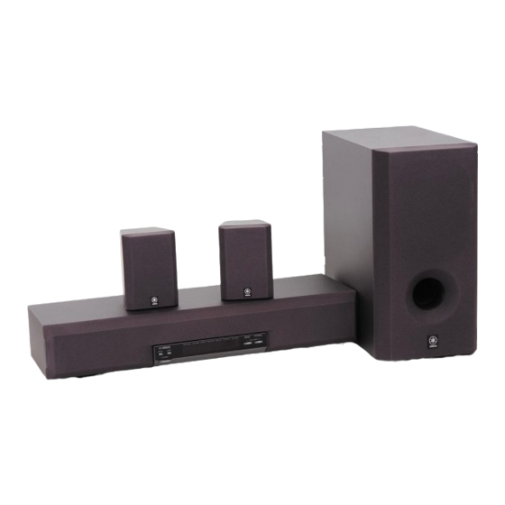
TV. You can also enjoy stronger bass and surround effects by adding the separately available YAMAHA NX-SW70, consisting of a subwoofer and two rear speakers. Includes Dolby Digital* and Dolby Pro... -
Page 4: Getting Started
Checking the Package Contents Check that the following accessories are included in the package. Remote control Readying the Remote Control Inserting the batteries Remove the battery compartment cover. Insert the four batteries (AAA, R03, UM-4 type) with + and – oriented properly. Close the battery compartment cover. - Page 5 Operational Area of the Remote Control Front speaker 30° 30° Battery replacement cycle Replace all four batteries when the operational range of the remote control starts to become shorter. Precautions on handling the remote control • The remote control may not be able to operate the front Approx.
-
Page 6: Names Of All Parts
(page 20) POWER (page 17) Turns the unit’s power on and off. This button also turns off the subwoofer’s power when a YAMAHA subwoofer and rear speakers NX-SW70 (sold separately) are connected. The STANDBY indicator will light when power is turned off using p on the remote control. - Page 7 Remote Control p (power) (page 17) Remote control selector buttons (page 23) VOL – (page 17) m (page 18) SET/DSP (pages 20 and 23) MENU (page 21) MENU – (page 21) SUBWOOFER – (page 18) NIGHT MODE (page 18) t (page 18) DSP ON/OFF (page 20) Transmission indicator Not used with this unit.
-
Page 8: Speaker Placement
YAMAHA rear speakers NX-AVS70 (sold separately) Depending on room conditions, it is possible to place YAMAHA rear speakers NX-AVS70 on shelves or hang them on the wall. Speakers should be placed about 1.8 m above the floor. About 1.8 m... -
Page 9: Installation
To prevent the front speaker unit from falling, secure it with the provided velcro strip when placing it on a television or other device. Also, use the height adjustment bracket on the rear of the front speaker unit when there is not enough space for installation or when the surface is sloped. - Page 10 INSTALLATION Using the Height Adjustment Brackets Loosen the screws securing the adjustment bracket. Loosen the screws. Lower the bracket so that the front speaker unit is level and securely tighten the screws. Lower the Securely tighten bracket and the screws. adjust.
-
Page 11: Connections
• After connections have been made, check one more time that wiring has been made properly. TV (monitor) DVD player, LD player, etc. Front speaker unit AC outlet Page 14 CONNECTIONS Pages 10 to 12 VCR, etc. YAMAHA subwoofer and rear speakers NX-SW70 (sold separately) Page 14... - Page 12 CONNECTIONS Connecting a TV or VCR Connecting a TV (monitor) with audio output terminals Front speaker unit DIGITAL 2 /PCM) AUDIO IN L Connect the audio output terminal on the TV (monitor) to the TV terminal on the front speaker unit using the provided audio connection cord.
- Page 13 Connecting to a TV (monitor) without audio output terminals Front speaker unit AUDIO IN L Audio connection cord (provided) AUDIO OUT R OUTPUT VCR, etc. There are two methods of making connection: 1. connecting only the VIDEO terminals or 2. connecting the THROUGH OUT terminals in addition to the VIDEO terminals. When only the VIDEO terminals are connected Connect the audio output terminals on the VCR to the VIDEO terminals on the front speaker unit using the provided audio connection cord.
- Page 14 CONNECTIONS Connecting a TV (monitor) to enjoy digital audio Connect one of these Optical fiber cable (EIA standard) (commercially available) Audio connection cord (1 pin) (commercially available) Connect the optical terminal or coaxial terminal of the LD or DVD player to the DIGITAL 1 (optical) terminal or DIGITAL 2 (coaxial) terminal of the front speaker unit using a commercially available optical fiber cable or audio connection cord (1 pin).
- Page 15 Connecting a CD Player or MD Recorder Connect one of these Optical fiber cable (EIA standard) (commercially available) AUDIO IN L Audio connection cord (1 pin) (commercially available) If the CD player or MD recorder has a digital output terminal, connect the optical or coaxial terminal on the CD player or MD recorder to the DIGITAL 1 (optical) terminal or DIGITAL 2 (coaxial) terminal on the front speaker unit using a commercially available optical fiber cable or audio connection cord (1 pin).
- Page 16 • When connecting your subwoofer, connect the input terminal on the subwoofer to the SUBWOOFER terminal on the front speaker unit using a commercially available audio connection cord (1 pin). • For details regarding connections, please refer to the instruction manuals for your subwoofer or the owner’s manual for the YAMAHA subwoofer and rear speakers NX-SW70 (sold separately).
-
Page 17: Adjusting The Speaker Output Levels
ADJUSTING THE SPEAKER OUTPUT LEVELS When reproducing a Dolby Surround source using a DSP program such as DOLBY PRO LOGIC or DOLBY DIGITAL ENHANCED, it is necessary to adjust each channel to the same output level in order to bring out the full digital effect of these sound fields. - Page 18 ADJUSTING THE SPEAKER OUTPUT LEVELS Adjust the level of the test tone using VOL +/–. (This sets the standard audio level you will be using.) Pressing VOL + increases the level, while pressing VOL – decreases the level. Adjust the level of each channel while listening to the test tone.
-
Page 19: Operation
This section describes how to select audio output from A/V component such as a TV, VCR, or DVD, LD, CD player, or MD recorder as input source to the Home Theater Sound System AV-S70 and how to adjust levels. First turn on the playback component and the TV, and then follow the steps given below. -
Page 20: Using Convenient Functions
USING CONVENIENT FUNCTIONS You can use convenient functions with the remote control during audio reproduction. Å Increasing the power of the mid- range Press t. • The TRUBASS* indicator will light in the display. • This will increase the level of the mid-range, giving more force to dialog and song lyrics. -
Page 21: Dsp Program (Digital Sound Field Processor Effect)
Program name VIRTUAL SURROUND (input source: Dolby Digital or Dolby Surround) MONO MOVIE When the front speaker unit and a YAMAHA subwoofer and rear speakers NX-SW70 (sold separately) are connected Program name VIRTUAL SURROUND (input source: Dolby Digital or Dolby Surround) -
Page 22: Using The Remote Control
DSP program name will be displayed. When only the front speaker unit is connected: VIRTUAL SURROUND DSP OFF When the front speaker unit and a YAMAHA subwoofer and rear speakers NX-SW70 are connected: DOLBY DIGITAL/ VIRTUAL SURROUND... -
Page 23: Menu Functions
The menu functions include: “Auto Power” for setting automatic power on/off, “Dimmer” for adjusting display brightness, “Input Name” for naming input, and “Delay Time” for adjusting the delay time used for surround sound. Adjustments on the menu functions should be performed with the remote control. -
Page 24: Adjusting The Delay Time
MENU FUNCTIONS Naming Input It is possible to give names to the AUX, DIGITAL 1 and DIGITAL 2 input terminals. (It is not possible to change the input names for the TV or VIDEO input terminals.) This function makes selecting input source easier by allowing you to give a name that quickly allows you to see which component is connected to the terminal in question. -
Page 25: Remote Control
REMOTE CONTROL OPERATING OTHER COMPONENTS USING THE REMOTE CONTROL Setting the manufacturer code for your TV, VCR or satellite tuner/cable TV on the remote control allows you to operate the front speaker unit and your TV, VCR or satellite tuner/cable TV by remote control. Note that there are two methods for setting the code: manual preset and auto preset. - Page 26 OPERATING OTHER COMPONENTS USING THE REMOTE CONTROL Using auto preset Turn on the power of the component (TV, VCR or satellite tuner/cable TV) to be controlled by the remote control. Press the remote control selector button corresponding to the component for which auto preset is to be performed.
- Page 27 Point the remote control at the component to be controlled (the component turned on in step 1) and press p repeatedly until the component’s power turns off. If the transmission indicator flashes twice, this indicates that you have cycled through all the codes stored in the memory of the remote control.
-
Page 28: Controlling A Tv
OPERATING OTHER COMPONENTS USING THE REMOTE CONTROL Controlling a TV You can control your TV by setting the corresponding manufacturer code for the remote control selector button “TV”. TV power ON/OFF Decreases TV volume Selects the next lower channel Mutes the TV Used to select 2-digit channels Rewinds the VCR* Stops the VCR*... - Page 29 Controlling a VCR You can control your VCR by setting the corresponding manufacturer code for the remote control selector button “VCR”. VCR power ON/OFF Decreases TV volume* Selects the next lower channel Mutes the TV* Rewind Stop Pause OPERATING OTHER COMPONENTS USING THE REMOTE CONTROL Press VCR.
-
Page 30: Glossary
By adding YAMAHA DSP processing to both the right and left front channels and the center channel, the CINEMA DSP program wraps the audience in a surround sound field... -
Page 31: Troubleshooting
If this happens, first disconnect the power cord, wait about 30 seconds, re-connect the power cord, and try the desired operation again. • When requesting repairs or after service of the YAMAHA subwoofer and rear speakers NX-SW70 (sold separately), be sure to bring along with this unit. -
Page 32: Specifications
Amplifier Section Rated Output Front ... 30 W + 30 W (1 kHz, 10% THD, 6 ohms) Signal-to-Noise Ratio ... 85 dB (AUX, IHF-A) Total Harmonic Distortion ... 0.08% (Input: AUX, 1 kHz, 12.5 W/6 ohms) Input Sensitivity/Impedance ... AUX, 200 mV/50 k-ohms Speaker Section Front Speakers Type ... -
Page 33: Index
Adjusting display brightness ... 21 Adjusting the bass (subwoofer level) ... 18 Adjusting the delay time ... 22 Adjusting the volume level ... 17 Automatically setting a manufacturer code ... 24 Auto Power Setting auto power on/off ... 21 AUX terminal ... 13 CINEMA DSP DSP program ... - Page 34 LIST OF MANUFACTURER’S CODES LISTES DES CODES FABRICANT VERZEICHNIS DER HERSTELLERCODES LISTA ÖVER TILLVERKARKODER ELENCO DEI CODICI DEL FABBRICANTE LISTA DE CÓDIGOS DE FABRICANTES LIJST VAN CODES VAN FABRIKANT ADMIRAL 0411, 0451, 0911, 1021, 1081 AIKO 0891 CITIZEN AKAI 0061, 0101, 0231, CLARIVOX 1191, 1351, 1591, CLATRONIC...
- Page 35 0071, 0721, 1441, MINERVA 1581, 1591, 1741, 1791 MISTRAL KAISUI 0591, 1321, 1331 MITSUBISHI KAMOSONIC 0601 KARCHER 0591, 0601, 0841, 1091, 1321, 1511, 1561, 2051 MIVAR KAWASHO 0761 KENDO 0261 KENNEDY 0021, 0351, 0951, 1981 KNEISSEL 2911 MULTITECH KONKA 2701 KORTING 0431, 1011, 1021, 1081, 1541...
- Page 36 TECHWOOD 0791 TEKNIKA 1171, 1231, 1261 AIWA TELE 1141 AKAI TELEAVIA 0571, 0651, 0731, 1821 TELEFUNKEN 0291, 0301, 0311, ALBA 0551, 0731, 1131, 1471, 1591, 1791, AMSTRAD 1801, 1811, 1821, ANITECH 1991, 2161, 2171, ANITSCH 2181, 2191, 2201, 2251, 2271, 2521, AUDIOSONIC 0002 2631 BAIRD...
- Page 37 VICTOR 0042, 0102, 0142 LIFESAT VIDEON 1162, 1172 WELTBLICK 0012 LUXOR WHITE WESTINGHOUSE 0032 MACAB XENON 0162 MASPRO YAMAHA 0042, 0122 YOKO 0012, 0062, 0072 MEDION METZ Satellite Tuner MICROMAXX 1323, 1343, 2711 MITSUBISHI AKAI 1273 MORGANS ALBA 0823, 1273...
- Page 38 YAMAHA ELECTRONICS (UK) LTD. YAMAHA HOUSE, 200 RICKMANSWORTH ROAD WATFORD, HERTS WD1 7JS, ENGLAND YAMAHA SCANDINAVIA A.B. J A WETTERGRENS GATA 1, BOX 30053, 400 43 VÄSTRA FRÖLUNDA, SWEDEN YAMAHA MUSIC AUSTRALIA PTY, LTD. 17-33 MARKET ST., SOUTH MELBOURNE, 3205 VIC., AUSTRALIA...