Huawei OptiX RTN 980 Quick Installation Manual
Radio transmission system v100
Hide thumbs
Also See for OptiX RTN 980:
- Quick installation manual (34 pages) ,
- Quick installation manual (44 pages)

Related Manuals for Huawei OptiX RTN 980


Summary of Contents for Huawei OptiX RTN 980
- Page 1 OptiX RTN 980 Radio Transmission System V100 IDU Quick Installation Guide (Indoor) Issue: 01 Date: 2018-10-30 HUAWEI TECHNOLOGIES CO., LTD.
- Page 2 Notice The purchased products, services and features are stipulated by the contract made bet ween Huawei and the customer. All or part of the products, services and features described in this document may not be within the purchase scope or the usage scope. Unless otherwise specified in the contract, all statements, information, and recommendations in this document are provided "AS IS"...
-
Page 3: Installation Process
Installation Process Start Page 2 Precautions Before You Start Installing PGND Page17 Cables Instructions and Precautions for Page 3 Pages Installing Power Handling Boards 18 to 19 Cables Precautions for Page 4 Handling the Toggle Lever Switch Page 19 Installing E1 Cables Pages Precautions for Installing Ethernet... -
Page 4: Commissioning Process
Commissioning Process Start Powering On the Page 29 Equipment Configuring the NE Page 30 Data (by Using the Web LCT) Pages Aligning the Pages Aligning the Single- 31 to 33 Antennas 31 to 32 Polarized Antennas Checking the Radio Pages Aligning the Dual- Page 33 Link Status... - Page 5 Precautions NOTE This document provides quick guidelines for hardware installation. This document does not describe pre-delivery assembly. This document describes only procedures for onsite installation. CAUTION Power Supply The equipment uses a -48 V/-60 V DC power supply. An AC power supply or a high-voltage power supply may cause equipment damage or even human injuries and therefore is forbidden.
- Page 6 Instructions and Precautions for Handling Boards CAUTION Do not hold a board without hand protection. Wear an ESD wrist strip or ESD gloves before handling a board. Wearing ESD gloves Wearing an ESD strip Holding a board without hand protection CAUTION Hold the front panel of a board with hands.
- Page 7 Precautions for Handling the Toggle Lever Switch • Position and description of the toggle lever switch O: OFF CAUTION Turn the toggle lever switch only after gently pulling it out. I : ON NOTE A dual-channel IF board does not have a toggle lever switch.
- Page 8 Precautions for Handling IDU-side IF Cables (Single- Channel IF Board) CAUTION CAUTION Connect or disconnect an IF cable only after Do not connect or disconnect an IF cable when the powering off the ODU. ODU is powered on. Connect or disconnect the IF cable . Power off the ODU.
- Page 9 Precautions for Installing IF Cables (Dual-Channel IF Board) CAUTION When installing an IF cable, connect one end of the cable to the ODU and then connect the other end of the cable to the IDU. Connect the IF cable to the IDU. Connect the IF cable to the ODU.
- Page 10 Precautions for Handling IF Boards CAUTION Remove or insert an IF board only after powering off the ODU. Remove the IF board. Insert the IF board. Power off the ODU. Remove or insert the IF board. Disconnect the IF jumper. Skip this step if a dual-channel IF board is concerned.
-
Page 11: Tools For Installation
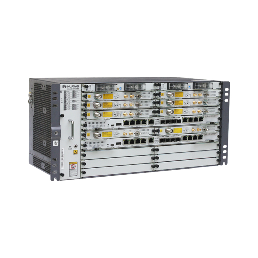
Tools for Installation Long measuring tape Level Phillips screwdriver Flat-head screwdriver Adjustable w rench Socket w rench Torque w rench Hex key COAX crimping tool Wire clippers Wire stripper RJ45 crimping tool Diagonal pliers Cold press pliers Needle-nose pliers Bayonet w rench Combination pliers File Multimeter... - Page 12 Introduction to the RTN 980 Equipment Exterior of the RTN 980 Front View Oblique View Side View...
- Page 13 Installation Requirements of the Cabinet and Mounting Ears NOTE Before installing the equipment, ensure that the cabinet has already been installed. The cabinet can be installed on the ESD floor or concrete floor. For details about how to install the cabinet, see the Cab inet Installation Guide delivered with the cabinet.
- Page 14 NOTE The default mounting ears are applicable to the situation where the equipment is installed in a 19 -inch standard cabinet. When installing the equipment in another type of cabinet, use other mounting ears as required. When installing the equipment in a 21-inch cabinet, install two sets of mounting ears. That is, retain the default mounting ears, and install another set of mounting ears for the equipment installed in the 21 -inch cabinet.
- Page 15 Installing the RTN 980 Installing the Chassis in the 19-Inch Cabinet Fixing Floating Nuts Floating nut Installation hole NOTE When tightening floating nuts, ensure a minimum of 25 mm space on the left and right sides of the RTN 980 for ventilation.
- Page 16 Installing the Chassis in the Cabinet Installing PGND Cables To the ground point on the column of the cabinet or the indoor ground bar Cable tray 30±3 Kgf.cm Connect PGND cables by using the removed screws. Installing the Chassis in the ETSI Cabinet Replacing Mounting Ears Fixing Floating Nuts NOTE...
- Page 17 Installing the Chassis in the Installing PGND Cables Cabinet To the ground point on the column of the cabinet or the indoor ground bar 30±3 Kgf.cm NOTE 30±3 Kgf.cm Install the cable tray if provided. Connect PGND cables by using the removed screws. Optional: Installing the E1 Panel Fixing Floating Nuts Floating nut...
- Page 18 Fixing the E1 Panel 30±3 Kgf.cm Installing PGND Cables on the E1 Panel To the ground point on the column of the cabinet or the indoor ground bar...
-
Page 19: Installing Boards
Installing Boards Guide rail Loosen the screws on the filler panel and remove the filler panel. Hold the ejector levers on the panel with hands and raise them to form an angle of approximately 45 degrees between the ejector levers and the panel. Push the board gently along the guide rail until the board is secure. Lower the two ejector levers of the board. - Page 20 Installing Cables for the RTN 980 Installing PGND Cables When installing a PGND cable in the ETSI cabinet, connect the PGND cable to the ground point on the left side of the chassis. When installing a PGND cable in the 19-inch cabinet, connect the PGND cable to the ground point of the left mounting ear of the chassis.
-
Page 21: Installing Power Cables
Installing Power Cables -48 V 50±5 Kgf.cm CAUTION If the AC power box (ETP 4890) is used, the IDU needs to use the BGND power cable and -48 V power cable that are delivered with the AC power box. For details on the AC power box and its cables, see the IDU hardware description. Open the cover and remove the bolt. - Page 22 Ensure that the circuit breaker of the PDU is set to the OFF state. Insert the DC connector into the power port of the PDU. Ensure that the two groups of power cables are connected to different wiring terminals, PIU boards in 1+1 hot backup mode Power box -48V...
- Page 23 Installing Ethernet Service Cables The EFP8, EM6T, EM6TA, EM6F, EM6FA, and EMS6 boards provide the FE ports. The CSHN, CSHNA, EM6T, EM6TA, EG4, and EG4P boards provide the GE electrical ports. EM6T board NOTE The Ethernet service port supports the MDI/MDI-X adaptive function. Therefore, you can assemble either a crossover cable or a straight-through cable.
- Page 24 Installing IF Jumpers Installing an IF Jumper The ISM6, ISV3, IF1, IFU2, ISU2, ISX2, and IFX2 boards provide the IF port. ISU2 board ODU switch CAUTION Before installing an IF jumper on a single-channel IF board, turn off the ODU switch on the IF board. If an RG-8U IF cable or a 1/2-inch IF cable is used, an IF jumper is required to connect the IF cable and IDU;...
-
Page 25: Installing Fibers
Installing Fibers Precautions CAUTION When installing or maintaining fibers, do not look into the optical port without eye protection. See Figure 1. Coil up the inter-office fibers on the ODF and then route them into the cabinet. Do not coil up external fibers in the cabinet. - Page 26 Installing Fibers The CQ1, SL1D, SL1DA, CSHN, CSHNA, EM6F , EM6FA, EMS6, EG4, and EG4P boards provide the optical port. SL1D board Installing STM-1e Cables The CQ1, SL1D, SL1DA board provides the STM-1e electrical port. SL1D board Installing NM Cables Installing the NM Cables (for a Gateway NE) The CSHN, CSHNA board provides the NMS/COM port.
- Page 27 Installing the NM Cables (for Multiple Interconnected NEs at a Site) NMS/COM NMS/COM NOTE Assemble a crossover cable or a straight-through cable on site. Ensure that the interconnected network cables do not form a loop and the standby CSH/CSTA board is not connected to another network cable.
- Page 28 Installing External Clock Cables Assembling External Clock Cables Based on the Pin Assignment Color Relationship CLK/TOD1 White/Orange Negative receive end of the external clock Twisted pair Orange Positive receive end of the external clock White/Green External time 1_N Twisted pair Green External time 1_P Negative transmit end of the external clock...
- Page 29 Installing Asynchronous and Synchronous Data Cables Assembling Asynchronous and Synchronous Data Cables Based on the Pin Assignment Pin Assignment Color Relationship Function White/Orange Transmits asynchronous data signals. Twisted pair Orange Grounding Receives asynchronous data signals. White/Green Twisted pair Green Grounding Blue Transmits synchronous data signals (TIP).
- Page 30 Installing External Alarm Cables Assembling External Alarm Cables Based on the Pin Assignment Color Relationship ALMO ALMI White/Orange External alarm signal input 1 Positive alarm signal output 1 Twisted pair Orange Grounding Negative alarm signal output 1 White/Green Positive alarm signal output 2 External alarm signal input 2 Twisted pair Green...
- Page 31 Cable Layout Effectiveness Cable Connections NM Cables Asynchronous and Synchronous Data PGND Cables Ethernet Service Cables Cables IF Jumpers Orderw ire Phone Cables External Alarm Cables Pow er Cables XPIC Cables E1 Cables Fibers/STM-1 Cables External Clock Cables Cable Layout Effectiveness...
-
Page 32: Powering On The Equipment
Powering On the Equipment CAUTION Before powering on the equipment, ensure that the installation of the ODU is completed and the ODU switch on the IF board is set to the OFF state. Status Description of Indicators Indicator Status Description Constantly on and green The power is functioning properly. - Page 33 Configuring NE Data (by Using the Web LCT) CSHN board NMS/COM You can use the Web LCT to configure NE data, including basic data of the NE, IF/ODU information of the radio link, parameters for the IF ports, and parameters for the ODU ports.
-
Page 34: Aligning Antennas
Aligning Antennas Aligning Single-Polarized Antennas Determine the azimuth of the antenna according to the installation position and height of the antenna. Adjust the elevation of the antenna to the horizontal position. Connect a multimeter to the RSSI port on the ODU at the local end and measure the voltage value V NOTE The red line of the multimeter is connected to the pin, and the black line of the multimeter is connected to the inner wall (ground pin). - Page 35 Front view of the lines tracked at different elevations of the antenna RSL value of each line 天线不同仰角下扫描路径的正面图 各路径信号值 Adjust the elevation adjustment screw. At the local end, gently adjust the elevation and azimuth until the RSL reaches the peak within the tracked range. Repeat Steps 3 to 4 to ensure that three signal peaks are tracked in both horizontal and vertical directions.
- Page 36 Use a multimeter to measure the RSL (P1) on the RSSI port of the horizontally polarized ODU at the local end. Power on the vertically polarized ODU at the local end. Use a multimeter to measure the RSL on the RSSI port of the vertically polarized ODU.
-
Page 37: Checking The Installation
Checking the Installation What to Check For The chassis must be installed securely in the position as specified in the engineering design documents. Each chassis component does not have any paint drop, damage, or stain. Otherwise, re -paint or clean the component. - Page 38 -38.4 V DC to -72 V DC Number of power outputs Eight power outputs under control of four circuit breakers. For the OptiX RTN 980 equipment, one circuit breaker is required to control one power output. Maximum current of each circuit...
- Page 39 Installing Mounting Ears for the C3 PDU Installing the C3 PDU in a 19-inch cabinet Installing the C3 PDU in an ETSI cabinet NOTE By default, the C3 PDU is installed in a 19-inch cabinet. When the C3 PDU is installed in an ETSI cabinet, the mounting ear needs to be removed and then installed in another direction.
- Page 40 Connections Between Power Cables NOTE PGND cable Pow er cable for the subrack C3 PDU can be used only in the central telecommunications room. A maximum of two RTN 980 NEs can be installed in a cabinet. Cover PGND cable NEG (-) RTN (+) PIU boards in 1+1 hot backup mode...
- Page 41 When stripping the insulation layer of a power cable, do not damage the metallic conductor of the power cable. If the bare crimp terminal is not provided by Huawei, change the value of L1 according to the actual value L of the bare crimp terminal.
- Page 42 Crimp the joint parts of the bare crimp terminal and Push the heat shrink tube A towards the connector until the conductor of the power cable by using a crimping the heat shrink tube covers the crimped parts of the bare tool.
- Page 43 • Installation procedure Strip a part of the insulation layer B of the power Route the conductor of the power cable into the cord cable according to the cross -sectional area of the end terminal A, and then align the conductor with the conductor, and ensure that the conductor C of the edge of the cord end terminal.
- Page 44 HUAWEI TECHNOLOGIES CO., LTD. Huawei Industrial Base Bantian Longgang Shenzhen 518129 People’s Republic of China www.huawei.com...